Negative Refraction and Focusing By a Left-Handed
Material Slab in Free Space
Koray Aydin, and Ekmel Ozbay
Nanotechnology Research Center and Department of Physics, Bilkent University, Bilkent, 06800 Ankara, Turkey [email protected]
Abstract: Negative refraction and focusing by a left-handed metamaterial (LHM) slab are
experimentally verified. We measured refractive index of slab as -1.86. The flat lens behavior of LHM is demonstrated for two different point source distances.
©2006 Optical Society of America
OCIS codes: (110.2990) Image formation theory; (120.5710) Refraction; (220.3630) Lenses 1. Introduction
Materials exhibiting negative values of dielectric permittivity (ε) and magnetic permeability (µ) are named as left-handed materials (LHM) and they have a negative index of refraction [1]. The first experimental demonstration of LHMs were achieved by arranging ε(ω) < 0 media and µ(ω) < 0 media periodically [2]. Experimental verification of negative refraction was reported shortly after, supporting the existence of neff < 0 medium [3]. A negative refractive
index allows a flat lens to bring EM waves into focus, whereas positive refractive index materials always require curved surfaces to focus EM waves [1,4].
In this work, we first present the left-handed transmission band and impedance matching, and then verify negative refraction at an impedance matched frequency. Finally we demonstrate focusing through a slab of left-handed metamaterial in free space.
2. Left-handed Transmission Band and Impedance-matching
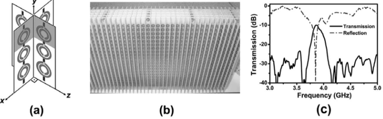
Figure 1(a) represents a schematic drawing of a 2D LHM structure. The shaded parts show a single unit cell, two SRRs and the wires are placed perpendicular to each other. The 2D LHM structure is composed of Nx = 5, Ny = 20,
and Nz = 40 unit cells, with lattice spacings ax = ay = az = 9.3 mm as seen in Fig. 1(b).
Fig. 1. (a) Schematic drawing of 2D LHM. Shaded parts represent the unit cell of the LHM structure. (b) 2D LHM structure used
for transmission, reflection and refraction experiments. (c) Measured transmission and reflection spectra of LHM structure.
Transmission and reflection measurements are performed in free space. The experimental results are depicted in Fig. 1(c). A transmission band is observed between 3.75 - 4.05 GHz. At this frequency range the effective parameters of the material (i.e. ε and µ) posses negative values [5,6], therefore the transmission band is indeed left-handed. The transmission peak is measured to be -9.9 dB at 3.86 GHz. At this frequency a dip in the reflection spectrum is observed, with a dip value of -38 dB. The impedance is matched to the free space at 3.86 GHz. Therefore, almost all of the EM waves enter inside the LHM structure without being reflected at the surface. The impedance of LHM will be equal to that of free space if the real parts of ε and µ are equal [4].
a1244_1.pdf QThN7.pdf
3. Negative Refraction and Focusing Through a Slab of LHM
We have set 3.86 GHz as our working frequency, to assure that the effect of the reflections on our results is kept at minimum, including losses due to reflection. The EM wave is sent through the LHM slab with an incident angle of
θi = 15°. The intensity distribution of the refracted EM wave is scanned by a monopole antenna mounted to a 2D
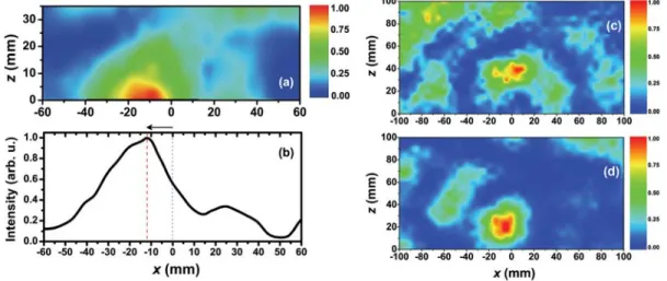
scanning table with ∆x = ∆z = 2.5 mm steps. Figure 2(a) displays the measured refraction spectrum at 3.86 GHz. The incident EM wave has a Gaussian beam profile centered at x = 0. As clearly seen in Fig. 2(a), the center of the outgoing Gaussian beam is shifted to the left side of the center of the incident Gaussian beam, which due to Snell’s law, corresponds to negative refraction. Figure 2(b) is the intensity distribution of an EM wave at the LHM-air interface. As can be seen in Fig. 2(b), the center of the refracted Gaussian beam (red dashed line) is measured at -12.5 mm away from the center of the incident Gaussian beam (blue dotted line). The refractive index of LHM is then calculated from Snell’s law as neff = -1.86.
Fig. 2: (a) Spatial intensity distribution of an outgoing EM wave at 3.86 GHz along the x-z plane. (b) Intensity profile of an EM
wave at the LHM-air interface (z = 0). Measured transmission spectra along the x-z plane for a point source located at (c) ds = 39
mm, and (d) ds = 78 mm away from the LHM lens.
We have employed a LHM lens with 40×20×10 layers along the x, y and z directions. A monopole antenna is used as the point source. The source is located away from the LHM lens at two different source distances of ds = 39 mm
(0.5λ) and ds = 78 mm (λ). The intensity distribution of an EM wave is scanned by another monopole antenna with
∆x = ∆z = 5 mm steps. Figure 2(c) provides the transmission spectrum for the omni-directional source located at ds =
39 mm away from the LHM lens. As seen in the figure, an image is formed at a focal length of z = 40 mm (~0.52λ). For the case where the point source is placed at ds = 78 mm, the image is observed at z = 20 mm (~0.26 λ) (Fig.
2(d)). As the point source is moved away from the LHM flat lens, the focal length is shifted towards the flat lens, which is consistent with the imaging theory.
The advantages of the flat lens presented here are: (1) The lens is constructed from an all-angle negative refractive index LHM slab, (2) it operates at a frequency where the transmission is at the maximum and the reflection is minimum, assuring that the experimental results are not any artifact of the reflections from the surface, (3) it is working in free space rather than an isolated waveguide environment, and (4) it enables sub-wavelength focusing by virtue of the negative refractive index.
4. References
[1] V. G. Veselago, “The electrodynamics of substances with simultaneously negative values of permittivity and permeability,” Sov. Phys. USPEKHI, vol. 10, p. 509, 1968.
[2] D. R. Smith, Willie J. Padilla, D. C. Vier, S. C. Nemat-Nasser, and S. Schultz, “Composite medium with simultaneously negative permeability and permittivity,” Phys. Rev. Lett., vol. 84, p. 4184, 2000.
[3] R. A. Shelby, D. R. Smith, and S. Schultz, “Experimental verification of a negative index of refraction,” Science 292, 77 (2001). [4] J. B. Pendry, “Negative refraction makes a perfect lens,” Phys. Rev. Lett. 85, 3966 (2000).
[5] K. Aydin, K. Guven, M. Kafesaki, L. Zhang, C. M. Soukoulis, and E. Ozbay, “Experimental observation of true left-handed transmission peak in metamaterials,” Opt. Lett. 29, 2623 (2004).
[6] K. Aydin, K. Guven, C. M. Soukoulis, and E. Ozbay, “Observation of negative refraction and negative phase velocity in left-handed metamaterials,” Appl. Phys. Lett. 86, 124102 (2005).