Inductance and resistance measurement method for vessel detection and coil
powering in all-surface inductive heating systems composed of outer squircle coils
Veli Tayfun Kilic, Emre Unal, and Hilmi Volkan Demir
Citation: AIP Advances 7, 056645 (2017); doi: 10.1063/1.4975354 View online: https://doi.org/10.1063/1.4975354
View Table of Contents: http://aip.scitation.org/toc/adv/7/5
Published by the American Institute of Physics
Articles you may be interested in
Coupling and power transfer efficiency enhancement of modular and array of planar coils using in-plane ring-shaped inner ferrites for inductive heating applications
Journal of Applied Physics 122, 014902 (2017); 10.1063/1.4992119
Wireless power transfer inspired by the modern trends in electromagnetics
Applied Physics Reviews 4, 021102 (2017); 10.1063/1.4981396
Research progress of wireless power transmission technology and the related problems
AIP Conference Proceedings 1820, 090023 (2017); 10.1063/1.4977407
Load characteristics of wireless power transfer system with different resonant types and resonator numbers
AIP Advances 7, 056601 (2017); 10.1063/1.4972851
Stress analysis of magnetically controlled reactor
AIP Advances 7, 056640 (2017); 10.1063/1.4975130
Design of an effective energy receiving adapter for microwave wireless power transmission application
Inductance and resistance measurement method
for vessel detection and coil powering in all-surface
inductive heating systems composed of outer
squircle coils
Veli Tayfun Kilic,1,aEmre Unal,1and Hilmi Volkan Demir1,2,a 1Department of Electrical and Electronics Engineering, Department of Physics, Nanotechnology Research Center, and Institute of Materials Science
and Nanotechnology, Bilkent University, Ankara 06800, Turkey
2School of Electrical and Electronic Engineering, Nanyang Technological University, Singapore 117602, Singapore
(Presented 4 November 2016; received 21 September 2016; accepted 5 November 2016; published online 30 January 2017)
In this work, we investigate a method proposed for vessel detection and coil powering in an all-surface inductive heating system composed of outer squircle coils. Besides conventional circular coils, coils with different shapes such as outer squircle coils are used for and enable efficient all-surface inductive heating. Validity of the method, which relies on measuring inductance and resistance values of a loaded coil at differ-ent frequencies, is experimdiffer-entally demonstrated for a coil with shape differdiffer-ent from conventional circular coil. Simple setup was constructed with a small coil to model an all-surface inductive heating system. Inductance and resistance maps were generated by measuring coil’s inductance and resistance values at different frequencies loaded by a plate made of different materials and located at various positions. Results show that in an induction hob for various coil geometries it is possible to detect a vessel’s presence, to identify its material type and to specify its position on the hob surface by considering inductance and resistance of the coil measured on at least two different frequencies. The studied method is important in terms of enabling safe, efficient and user flexible heating in an all-surface inductive heating system by automatically detect-ing the vessel’s presence and powerdetect-ing on only the coils that are loaded by the vessel with predetermined current levels. © 2017 Author(s). All article content, except where otherwise noted, is licensed under a Creative Commons Attribution (CC BY) license (http://creativecommons.org/licenses/by/4.0/). [http://dx.doi.org/10.1063/1.4975354]
I. INTRODUCTION
Most recently, induction systems are becoming more popular and their application areas are getting wider. Because of their high efficiency, being safe and controllability properties, induction systems are used in various applications including heating, wireless power transmission, metal melt-ing, etc. Cooking is one of the common application areas of induction systems. In conventional induction hobs, heating is achieved with large coils mounted beneath the hob surface. However, in these systems for efficient heating users should locate vessels having shapes and sizes similar to those of the coils and right on top of the coils. To overcome these restrictions, all-surface inductive heating systems are proposed, where an array of small coils is used.1,2In all-surface induction hobs, vessel’s presence should be detected and its material type should be identified together with its position on the hob surface. Therefore, only the coils that are loaded by the vessel are powered up with predeter-mined current magnitudes for efficient and safe heating. Since all-surface induction hob is a very new technology, there are few studies in literature about vessel detection. Damping factor measurement
aElectronic mails:[email protected]and[email protected]
056645-2 Kilic, Unal, and Demir AIP Advances 7, 056645 (2017) is one method proposed to detect vessels on conventional induction hobs.3,4Although this method is useful for detecting vessels, with this approach it is not possible to easily specify the exact size and location of vessels together with their material types. Here, on the other hand, we investigate a simple and a robust method to detect a vessel and uniquely identify its material type and determine its position on the hob surface. Also, with the proposed method shape and size of the cooking vessel can also be defined in all-surface inductive heating systems.
The proposed method relies on measuring inductance and resistance of the loaded coils. The method has been previously studied with conventional shape circular coils.5However, in this work, we proved validity of the proposed method for newly designed outer squircle coils, which enable efficient all-surface heating.6 To this end, inductance and resistance values of a coil having outer squircle-inner circular shape that is loaded by vessels made of different materials at different positions were successfully measured at different frequencies. Results indicate that for different coil geometries with the proposed method it is possible to specify a vessel’s shape, size and position together with its material type, which enables efficient and safe heating of all-surface induction hobs by powering on only the corresponding coils that are loaded by the vessel with predetermined current amplitudes. The study is an original contribution in terms of demonstrating validity of the method for coils having shapes different from that of conventional circular coils.
II. MEASUREMENT SETUP AND RESULTS
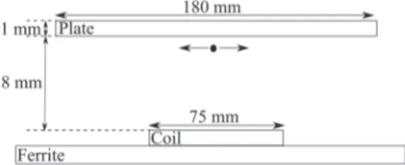
In our measurements, to model an induction hob we constructed a simple system setup. Side view of the constructed system is shown in Figure1.
In the measurements, single coil with outer squircle-inner circular shape was used. This coil have architecture exactly the same with that reported in literature.6 Inner diameter of the coil is set to be 30 mm. Also, side length of the outer squircle-inner circular coil is equal to 75 mm. Coil was loaded by a cylindrical shape steel (AISI 430) and an aluminum plate with 180 mm diameter and 1 mm thickness. The plate was located on a constant horizontal plane 8 mm above from the coil. Although the coil was fixed at its position, the plate moved on and scanned the horizontal plane at a fixed distance from the coil. Also, in the system a ferrite layer was placed just below the coil. Locating ferrites below coils is a well-known method to increase efficiency in induction systems.7,8
We first obtained measurements with the stainless steel (AISI 430) plate. Mapping of the induc-tance and resisinduc-tance values measured at 20 KHz while the steel plate moves on the constant x-y plane is represented in Figure2. In the figure measured inductance and resistance values have almost sym-metric distributions. This is because of the coil’s symsym-metric outer squircle-inner circular architecture and the plate’s cylindrical geometry. The small variations that violates symmetry are because of the plate’s not being completely parallel to the coil during measurement.
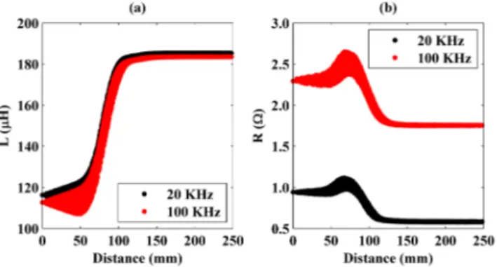
Inductance and resistance values of the unloaded coil were measured to be 188 µH and 0.5 Ω, respectively. As the plate projection starts to intersect with the coil, measured inductance value first increases and then decreases such that it decreases to a value lower than the inductance of the unloaded squircle coil. On the other hand, resistance of the coil monotonically increases as the intersection area of the plate’s projection and the coil gets wider. These results are clearly seen in Figure3, where change of the inductance and resistance values with the distance between the centers of the plate’s projection and the coil are illustrated.
FIG. 2. Maps of inductance and resistance values of the system measured at 20 KHz, where the outer squircle-inner circular shape coil is loaded by the steel plate that moves on the constant horizontal plane 8 mm above from the coil. Here, coil is fixed at its place such that its center is at (0,0) position. Also, the white dashed lines with squircle shape represent the points at which the plate projection and the coil are tangential. End points of these dashed lines are marked with pink dashed lines passing through x = +-127 mm and y = +-127.5 mm.
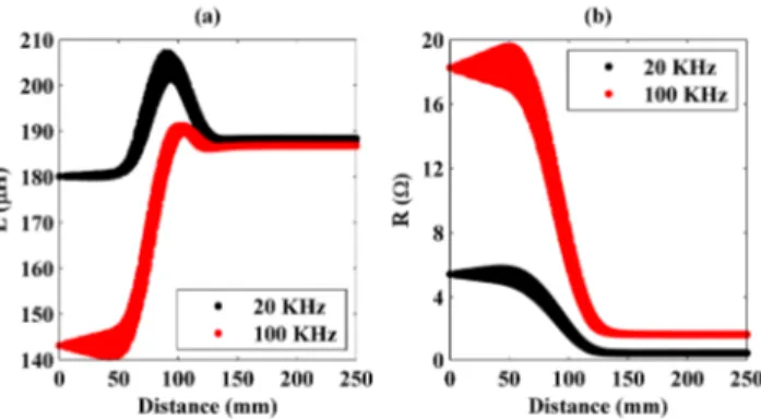
Measurements were repeated with the aluminum plate. Change of the inductance and resistance values in the new system are presented in Figure4.
In the system, where the steel plate is used (Figure3), inductance values first increase and then decrease as the plate gets closer to the coil. On the other hand, there are monotonic increases in the resistance values. Monotonic increases are important to uniquely determine the plate’s distance to the coil and so its position on the hob. Therefore, by measuring resistance values of a loaded coil at different frequencies one can determine the position of the steel plate. However, this information is not enough to uniquely identify its material type. To uniquely identify the plate’s material type inductance values should also be inspected. On the contrary, in the system, where the aluminum plate is used (Figure 4), resistance values first increase and then decrease as the pate’s projection covers the coil more, whereas, inductance values decrease continuously as the plate projection gets closer to and covers more of the coil. Again, to uniquely identify the plate material type and specify its position inductance and resistance values measured at various frequencies should be taken into account.
In addition, in the figures, measured resistance values are considerably higher at 100 KHz than those at 20 KHz. This is because of the decrease in skin depth of the plate materials at high frequencies. On the other hand, inductance values are lower at 100 KHz than those at 20 KHz. Although, the difference between the measured inductance values is very clear in the system, where the steel plate is used, it is considerably smaller in the system, where the aluminum plate is placed. This distinction is due to the plate’s material type. Decrease in the loaded coil’s inductance occurs because of reverse eddy currents on the load, thus large decrease in equivalent inductance at high frequencies implies high coupling between the plate and the coil.
FIG. 3. Measured inductance (a) and resistance (b) values of the system, where the steel plate is used, at 20 and 100 KHz vs. distance between the centers of the plate’s projection and the coil.
056645-4 Kilic, Unal, and Demir AIP Advances 7, 056645 (2017)
FIG. 4. Measured inductance (a) and resistance (b) values of the system, in which the aluminum plate is used, at 20 and 100 KHz vs. distance between the centers of the plate’s projection and the coil.
Since inductance and resistance values at a specific frequencies are related with magnitude and angle of the coil’s impedance, it is also possible to uniquely identify the plate material type and to determine its position by using magnitude and angle values of the coil’s impedance at different frequencies. It might be preferred in a heating system because coil’s impedance can directly be measured from voltage and current signals supplied to the coil. Moreover, from inductance and resistance mapping data it is possible to derive inductance and resistance changes as a function of intersection area between the plate’s projection and the coil. Same measurements were conducted for a circular shape coil and similar results and behaviors were obtained. Since its geometry is easier, inductance and resistance variations as a function of coverage area of the plate’s projection on the circular coil were calculated. Similarly, changes of the magnitude and the angle of the coil’s impedance with the coverage area were investigated, too.5
III. CONCLUSION
In this work, we investigated a method to uniquely identify vessel material type and its position on an inductive heating system. It was experimentally shown that one can determine vessel’s material type and the distance between the vessel’s projection and the coil by measuring inductance and resistance of the coil at various frequencies. This method is proved to be useful not just for the conventional shape circular coils but also for outer squircle-inner circular shape coils designed for all-surface induction hobs. Since inductance and resistance values are related with magnitude and angle of the coil’s impedance, they were also shown to be used for iden-tification and determination processes. Therefore, by applying small signals to an array of coils with various architectures in all-surface induction hobs and measuring voltage and current signals on each coil one can determine the vessel’s shape, size and position together with its material type, which enables efficient and safe heating together with user flexibility through automatically detecting the vessel’s presence and powering on only the loaded coils with predetermined cur-rent magnitudes. We believe that the study is beneficial in terms of demonstrating validity of the method for two dimensional (2D) planar coils having various shapes. Future study related with this work might be implementation of the proposed method to an all-surface inductive heating sys-tem and measuring performance of the syssys-tem in terms of accuracy and speed of the load decision process.
1O. Lucia, J. Acero, C. Carretero, and J. M. Burdio,IEEE Ind. Electron. Mag.7, 35 (2013). 2O. Lucia, P. Maussion, E. J. Dede, and J. M. Burdio,IEEE Trans. Ind. Electron.61, 2509 (2014). 3W. Essig, F. Bogdanski, K.-G. Fettig, and J. Horn, U.S. patent 5,428,207 (27 June 1995).
4M. E. Tulu and D. Yildirim, in 12th International Conference on Environment and Electrical Engineering (EEEIC) (IEEE,
Wroclaw, Poland, 5–8 May 2013), pp. 1–6.
5V. T. Kilic, E. Unal, and H. V. Demir,Sensors16, 363 (2016).
6V. T. Kilic, E. Unal, E. Gonendik, N. Yilmaz, and H. V. Demir, IEEE Trans. Ind. Electron. PP, 1. 7W. A. Roshen and D. E. Turcotte,IEEE Trans. Magn.24, 3213 (1988).