Negative refraction through an
impedance-matched left-handed metamaterial slab
Koray Aydin and Ekmel Ozbay
Nanotechnology Research Center and Department of Physics, Bilkent University, Bilkent 06800, Ankara, Turkey Received July 8, 2005; revised September 15, 2005; accepted September 22, 2005
We report the transmission and reflection characteristics of a two-dimensional (2D) left-handed metamaterial (LHM). A well-defined left-handed (LH) transmission band with a peak value of −9.9 dB is obtained at fre-quencies where both effective permittivity and permeability are negative. A very sharp dip共−38 dB兲 at the reflection spectrum due to impedance matching at the surface of a 2D LHM is observed. Gaussian beam shift-ing experiments are performed to study the LH properties of a LHM structure. The structure has a negative refraction of electromagnetic waves in a certain frequency range. The negative refractive index values obtained for four different incident angles are in good agreement. © 2006 Optical Society of America
OCIS codes: 120.7000, 120.5700, 120.5710, 260.2110.
1. INTRODUCTION
Recently, novel types of artificially constructed materials, so called left-handed metamaterials (LHMs), have been extensively studied. In his theoretical work,1 Veselago predicted that it is possible to achieve a negative refrac-tive index with materials that simultaneously have nega-tive values of dielectric permittivity共⑀兲 and magnetic per-meability共兲. In such media, the electric, magnetic, and wave vector components form a left-handed (LH) coordi-nate system; hence the name left-handed material is used as a description. Veselago also investigated various inter-esting optical properties of LHMs such as backward Cher-enkov radiation and reversal of the Doppler effect.1In or-dinary materials,⑀ and are generally positive. However, artificially constructed periodic structures allow negative values of⑀ and . The periodic arrangement of thin-wire structures are shown theoretically and experimentally to exhibit a plasma frequency at the microwave frequency level.2,3These structures behave similarly to a high-pass filter, meaning that the effective permittivity will take on negative values below the plasma frequency. Pendry et al. proposed a resonant structure, called a split-ring resona-tor (SRR), that enhances the electromagnetic response owing to its capacitive elements.4 When these SRRs are combined in a periodic medium, the magnetic permeabil-ity possesses negative values at frequencies close to the magnetic plasma frequency.
The first experimental realization of LHMs was achieved by Smith et al.5 Periodic arrays of SRRs and thin-wire structures were shown to exhibit a LH trans-mission band at frequencies where both ⑀ and are negative.5–7This experiment was later followed up by the direct measurement of the negative index of refraction.8 Although the negative refraction phenomenon is dis-cussed on the basis of the dispersion of LHMs,9 further theoretical calculations10 and experimental studies11–13 have supported the existence of negative refraction. Nega-tive refraction is also achievable in two-dimensional (2D) dielectric photonic crystals that have a periodically
modu-lated positive permittivity and a permeability of unity.14–17
In this paper, we investigate the transmission, reflec-tion, and refraction characteristics of a two-dimensional (2D) LHM. Our paper is organized as follows. First, we present the transmission and reflection spectra of a 2D LHM that exhibits a peak in the transmission spectrum and a dip in the reflection spectrum at LH frequencies. We then verify the negative refraction experimentally by using a method different from that of the wedge structure experiments. The Gaussian beam shifting method at the second LHM–air interface is utilized to measure the re-fractive index value.
2. EXPERIMENT AND ANALYSIS
LHM structures are generally composed of SRRs and thin-wire grids. A periodic thin-wire medium is respon-sible for the negative effective permittivity, whereas the periodic SRR structure provides negative effective perme-ability. SRR and wire patterns are fabricated on the front and back sides of FR4 printed circuit boards. The metal used for deposition is copper and has a thickness of 30m. A single SRR cell has a diameter of 7.2 mm, the widths of both rings are 0.9 mm, and the split width and the distance between inner and outer rings are both 0.2 mm.13 The length and width of the continuous thin-wire structures are l = 19 cm and w = 0.9 mm, respectively. Figure 1(a) presents a schematic drawing of a 2D LHM structure. The shaded parts show a single unit cell; two SRRs and the wires are placed perpendicular to each other. The 2D LHM structure is composed of Nx= 5, Ny
= 20, and Nz= 40 unit cells, with lattice spacings ax= ay
= az= 9.3 mm as seen in Fig. 1(b).
Transmission and reflection measurements are per-formed in free space. The experimental measurement setup consists of a HP 8510C network analyzer and mi-crowave horn antennas. The incident electromagnetic (EM) wave propagates along the x direction, while E is
K. Aydin and E. Ozbay Vol. 23, No. 3 / March 2006 / J. Opt. Soc. Am. B 415
along the y direction and H is along the z direction [see Fig. 1(a)]. Transmitter and receiver horn antennas are connected to the HP-8510C network analyzer to measure the transmission coefficients. First we measured the transmission spectrum in free space (i.e., without a LHM structure). This measurement was used as the calibration data for the network analyzer. Then we inserted the structure between the horn antennas, and we performed the transmission measurements by maintaining distance between the fixed transmitter and receiver antennas. The distance between the horn antennas are kept at 35 cm to get rid of near- field effects. For the reflection measure-ments, two horn antennas were placed close to each other by keeping the angle between the antennas very small. The transmitter horn antenna sends the EM wave to the surface, and the receiver antenna measures the ampli-tude of the reflected EM waves. For calibration purposes we placed a thick slab of metal (since metals reflect all of the incident EM waves) 12 cm away from the antennas. The metamaterial was also placed at a same distance away from the antennas.
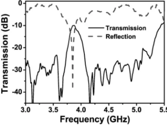
Figure 2 depicts the measured transmission (solid curve) and reflection (dashed curve) spectra of a 2D LHM in the range 3.0– 5.5 GHz. The SRR structure is respon-sible for the negative permeability in the frequency range 3.55– 4.05 GHz.13The periodic wire medium has a plasma frequency at 8.0 GHz, below which the effective dielectric permittivity takes negative values.13It is well known that if there exists a frequency region where effective⑀ and are both negative, a LH transmission band is likely to occur.5,6,11,13In our case, a transmission band is observed
between 3.75– 4.05 GHz (Fig. 2). At this frequency range the effective parameters of the material (i.e.,⑀ and ) pos-sess negative values; therefore the transmission band is indeed left-handed. The transmission peak measures −9.9 dB at 3.86 GHz.
A dip in the reflection spectrum is observed at 3.86 GHz, corresponding to a dip value of −38 dB. At this specific frequency, the impedance is matched to the free space. Therefore, almost all of the EM waves enter the LHM structure without being reflected at the surface.
If the real parts of⑀ and are equal, the impedance of LHM will be equal to that of free space.18As seen in Fig. 2, the impedance-matched frequency region is very nar-row. Such a small range for an impedance-matched fre-quency region is expected, since is known to vary rap-idly between the resonance and magnetic plasma frequency, although⑀ varies slowly.4,19
Although the reflection spectra of a SRR-only and a wire-only medium ave been studied previously,20,21to our knowledge no experimental evidence of an impedance-matched metamaterial exists. Impedance matching at the surface of a metamaterial is desired, since it reduces the complications of front-face reflection22 and ensures that the negatively refracted beam is not the result of any ex-perimental artifacts.23 Much more energy is transferred into the medium at impedance-matched frequencies. Therefore, the higher transmission共−9.9 dB兲 can be ex-plained by better impedance matching between the free space and the LHM for our particular design. Addition-ally, the matched impedance at the surface ensures the validity of the previously reported phase shift experi-ments for the same structures.13
Observations of negative refraction through left-handed metamaterials are performed mainly by using wedge-shaped samples.8,11–13Furthermore, a phase shift experiment is a way to verify and calculate the negative refractive index.13Here we present an alternative way to measure the refractive index of LHMs. The experimental procedure is similar to that of our previous studies on the negative refraction of 2D photonic crystals.15,17
The refraction spectrum is measured by a setup con-sisting of a microwave horn antenna as the transmitter
Fig. 1. (a) Schematic drawing of 2D LHM. Shaded parts repre-sent the unit cell of the LHM structure. (b) 2D LHM structure used for transmission, reflection, and refraction experiments.
Fig. 2. Measured (a) transmission (solid curve), and (b) reflec-tion (dashed curve) spectra of a 2D LHM structure between 3.0– 5.5 GHz.
Fig. 3. Schematic drawing of the experimental setup for verify-ing a negative refractive index. An electromagnetic wave is transmitted to the first interface by a microwave horn antenna with an anglei. The EM wave is refracted with an angler
through a slab of a LHM structure.
and a monopole antenna as the receiver. The size of the monopole antenna is 3.8 cm. Figure 3 shows the sche-matic view of the experimental setup. The 2D LHM slab has 10 layers along the incidence direction and 40 layers along the lateral direction. The horn antenna is on the negative side of the LHM structure with respect to its central axis. The source is 10 cm共1.5兲 from the first in-terface of the LHM slab. Full width at half-maximum of the beam at the interface is comparable to the wavelength and smaller than the size of the incident surface共5兲. The spatial intensity distribution along the second LHM–air interface is scanned in ⌬x=2.5 mm steps. Initially, the EM wave is sent through the LHM sample with an inci-dent angle ofi= 15°.
Figure 4 shows the transmission spectrum as a func-tion of the frequency and lateral posifunc-tion. The center of the outgoing Gaussian beam is shifted to the left side of the center of the incident Gaussian beam. This shift im-plies that the angle of refraction is negative; hence the re-fractive index, owing to Snell’s law, becomes negative. The EM wave is evidently refracted at the negative side for frequencies in the range 3.84– 3.89 GHz. Since at these frequencies better impedance matching is achieved, these experimental results cannot be evidence of any unex-pected experimental artifacts such as reflection.
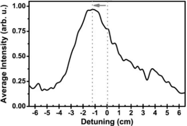
Figure 5 displays the refraction spectrum at 3.86 GHz, where the highest transmission and lowest reflection were observed. The center of the refracted Gaussian beam is −1.25 cm from the center of the incident Gaussian beam. We remind the reader that the incident field has a Gaussian beam profile centered at x = 0 (not shown in the figure). One can easily find the refractive index value by
applying Snell’s law, where nairsini= nLHMsinr. The
angle of refraction can be defined in terms of the beam shift 共ds兲 and width of the LHM slab 共wLHM兲 as r
= arctan共ds/ wLHM兲. The effective refractive index of the
LHM is then calculated: neff= −1.91. We have previously
performed wedge and phase shift experiments on the same structure.13 The refractive index values obtained from wedge experiments共neff= −1.95兲 and phase shift
ex-periments共neff= −2.00兲 are in quite good agreement with
our experimental results.
We performed the same experiment for three more in-cident angles:i= 10°, 20°, and 30°. Table 1 shows the
ex-perimental results obtained from these measurements. The peak of the Gaussian beam is observed at 7.5, 15.0, and 25.0 mm from the center of the incident Gaussian beam, respectively. The effective refractive index values obtained from these measurements are −2.11 fori= 10°,
−2.10 fori= 20°, and −1.89 fori= 30°. The agreement
be-tween the beam shift experiments for four different inci-dent angles and also with the wedge and phase shift ex-periments is quite good. Since the index of refraction is determined by the material parameters effective⑀ and ef-fective, one in fact expects to obtain the same values for different angles of incidence. However, the situation is different in 2D photonic crystals, since refraction depends strongly on the wave vector.
3. CONCLUSION
In conclusion, we have studied the transmission and re-flection characteristics of a two-dimensional LHM struc-ture. A left-handed transmission band is observed in a fre-quency range where both effective permittivity and effective permeability are negative. The transmission peak value is quite high共−9.9 dB兲 for a structure made of metal. We have observed a very sharp dip in the reflection spectrum, which is due to impedance matching at the sur-face. The reflection is very low at 3.86 GHz with a dip value of −38 dB; therefore all of the incident EM waves can propagate inside the LHM structure. This is an im-portant advance in metamaterial development, that when ⑀ and are equal and both negative, then we obtain a well-matched, negative index material. The Gaussian beam shifting experiment is performed on the structure, and a negative refractive frequency region is observed. The effective index values obtained for four different angles of incidence are in good agreement.
ACKNOWLEDGMENTS
This work was supported by EU-DALHM, EU NOE-METAMORPHOSE, EU NOE-PHOREMOST, and
TUBI-Table 1. Refractive Index Values for Different Incident Angles
Incident Angle Peak Distance Refractive Index
10° 7.5 mm −2.11
15° 12.5 mm −1.91
20° 15.0 mm −2.10
30° 25.0 mm −1.89
Fig. 4. (Color online) Transmission spectrum as a function of frequency and the lateral position at the LHM–air interface.
Fig. 5. Refraction spectrum at 3.86 GHz. The center of the Gaussian beam is shifted to the left, which means the refractive index is negative at this frequency.
TAK under Project No. 104E090. One of the authors (Ek-mel Ozbay) acknowledges partial support from the Turkish Academy of Sciences. K. Aydin is the correspond-ing author and can be reached by e-mail at [email protected].
REFERENCES
1. V. G. Veselago, “The electrodynamics of substances with simultaneously negative values of permittivity and permeability,” Sov. Phys. Usp. 10, 509–514 (1968). 2. J. B. Pendry, A. J. Holden, W. J. Stewart, and I. Youngs,
“Extremely low frequency plasmons in metallic mesostructures,” Phys. Rev. Lett. 76, 4773–4776 (1996). 3. J. B. Pendry, A. J. Holden, D. J. Robbins, and W. J.
Stewart, “Low frequency plasmons in thin-wire structures,” J. Phys.: Condens. Matter 10, 4785–4809 (1998).
4. J. B. Pendry, A. J. Holden, D. J. Robbins, and W. J. Stewart, “Magnetism from conductors and enhanced nonlinear phenomena,” IEEE Trans. Microwave Theory Tech. 47, 2075–2084 (1999).
5. D. R. Smith, W. J. Padilla, D. C. Vier, S. C. Nemat-Nasser, and S. Schultz, “Composite medium with simultaneously negative permeability and permittivity,” Phys. Rev. Lett. 84, 4184–4187 (2000).
6. R. A. Shelby, D. R. Smith, S. C. Nemat-Nasser, and S. Schultz, “Microwave transmission through a two-dimensional, isotropic, left-handed metamaterial,” Appl. Phys. Lett. 78, 489–491 (2001).
7. K. Aydin, K. Guven, M. Kafesaki, L. Zhang, C. M. Soukoulis, and E. Ozbay, “Experimental observation of true left-handed transmission peaks in metamaterials,” Opt. Lett. 29, 2623–2625 (2004).
8. R. A. Shelby, D. R. Smith, and S. Schultz, “Experimental verification of a negative index of refraction,” Science 292, 77–79 (2001).
9. P. M. Valanju, R. M. Walser, and A. P. Valanju, “Wave refraction in negative-index media: always positive and very inhomogeneous,” Phys. Rev. Lett. 88, 187401-1–187401-4 (2002).
10. J. Pacheco, Jr., T. M. Grzegorczyk, B.-I. Wu, Y. Zhang, and J. A. Kong, “Power propagation in homogeneous isotropic frequency-dispersive left-handed media,” Phys. Rev. Lett. 89, 257401-1–257401-4 (2002).
11. C. G. Parazzoli, R. B. Greegor, K. Li, B. E. Koltenbah, and
M. Tanielian, “Experimental verification and simulation of negative index of refraction using Snell’s law,” Phys. Rev. Lett. 90, 107401-1–107401-4 (2003).
12. A. A. Houck, J. B. Brock, and I. L. Chuang, “Experimental observations of a left-handed material that obeys Snell’s law,” Phys. Rev. Lett. 90, 137401-1–137401-4 (2003). 13. K. Aydin, K. Guven, C. M. Soukoulis, and E. Ozbay,
“Observation of negative refraction and negative phase velocity in left-handed metamaterials,” Appl. Phys. Lett. 86, 124102-1–124102-3 (2005).
14. M. Notomi, “Theory of light propagation in strongly modulated photonic crystals: refractionlike behavior in the vicinity of the photonic band gap,” Phys. Rev. B 62, 10696–10705 (2000).
15. Ertugrul Cubukcu, Koray Aydin, Ekmel Ozbay, S. Foteinopoulou, and Costas M. Soukoulis, “Electromagnetic waves: negative refraction by photonic crystals,” Nature (London) 423, 604–605 (2003).
16. E. Cubukcu, K. Aydin, S. Foteinopolou, C. M. Soukoulis, and E. Ozbay, “Subwavelength resolution in a two-dimensional photonic crystal based superlens,” Phys. Rev. Lett. 91, 207401-1–207401-4 (2003).
17. K. Guven, K. Aydin, K. B. Alici, C. M. Soukoulis, and E. Ozbay, “Spectral negative refraction and focusing analysis of a two-dimensional left-handed photonic crystal lens,” Phys. Rev. B 70, 205125-1–205125-5 (2004).
18. J. B. Pendry, “Negative refraction makes a perfect lens,” Phys. Rev. Lett. 85, 3966–3969 (2000).
19. T. Koschny, M. Kafesaki, E. N. Economou, and C. M. Soukoulis, “Effective medium theory of left-handed materials,” Phys. Rev. Lett. 93, 107402-1–107402-4 (2004). 20. E. Ozbay, K. Aydin, E. Cubukcu, and M. Bayindir, “Transmission and reflection properties of composite double negative metamaterials in free space,” IEEE Trans. Antennas Propag. 51, 2592–2595 (2003).
21. R. W. Ziolkowski, “Design, fabrication and testing of double negative metamaterials,” IEEE Trans. Antennas Propag. 51, 1516–1529 (2003).
22. P. F. Loschialpo, D. W. Forester, D. L. Smith, F. J. Rachford, and C. Monzon, “Optical properties of an ideal homogeneous casual left-handed metamaterial slab,” Phys. Rev. E 70, 036605-1–036605-1 (2004).
23. D. R. Smith, J. B. Pendry, and M. C. K. Wiltshire, “Metamaterials and negative refractive index,” Science 305, 788–792 (2004).