German Edition: DOI: 10.1002/ange.201606031
Mesoporous Metal Films
Very Important Paper
International Edition: DOI: 10.1002/anie.201606031First Synthesis of Continuous Mesoporous Copper Films with
Uniformly Sized Pores by Electrochemical Soft Templating
Cuiling Li, Bo Jiang, Zhongli Wang, Yunqi Li, Md. Shahriar A. Hossain, Jung Ho Kim,
Toshiaki Takei, Joel Henzie, :mer Dag, Yoshio Bando, and Yusuke Yamauchi*
Abstract: Although mesoporous metals have been synthesized by electrochemical methods, the possible compositions have been limited to noble metals (e.g., palladium, platinum, gold) and their alloys. Herein we describe the first fabrication of continuously mesoporous Cu films using polymeric micelles as soft templates to control the growth of Cu under sophisticated electrochemical conditions. Uniformly sized mesopores are evenly distributed over the entire film, and the pore walls are composed of highly crystalized Cu.
C
reating extended metallic 3D architectures is important because such kind of well-patterned networks improves material utilization efficiency and catalytic activity.[1] Thenanoscale structure of metals have been manipulated through various physical and synthetic routes. For example, top down nanofabrication can generate precisely defined structures down to the nanometer level, but making complex 3D structures is challenging.[2] Likewise, free-standing metal
nanoparticles can be assembled into large-scale superstruc-tures, but the process tends to be rather slow.[3] Especially,
mesoporous metals have sparked great interest due to their large surface areas and uniformly-sized pores, opening up a wide range of applications.[4]Growing metals in sacrificial
templates has been extensively studied by developing new kinds of hard and soft templates that can guide the deposition of metals and then be removed to reveal the mesoporous metallic structures.[4b,c,5] The lyotropic liquid crystal (LLC)
method[6] has been designed to work in combination of
electrochemical processes, and has been further extended for the synthesis of various mesoporous metals. To our knowl-edge, however, the compositions of mesoporous/nanoporous metals have been mostly limited in noble metals, such as Pt,[7]
Au,[8]Pd,[9]and their mixtures,[10]despite the diversity of the
morphologies and the wide range of usage. To extend the
utility of the mesoporous materials and make them ubiqui-tous, we must focus on non-noble metals that are far more Earth abundant than noble metals. The preparation of porous non-noble metals, however, is still very challenging because of their low reduction potentials, high susceptibility upon exposure to solution and air, and uncontrollable deposition behaviors.[11]
Copper (Cu) is a good candidate for mesoporous synthesis because it is a relatively abundant metal and has been well known to exhibit size-dependent properties in various appli-cation fields (e.g., sensing, conductivity, anti-bacteria, selec-tive conversion of CO2into fuels).[12]In particular, the high
surface area and fast diffusion through the porous network makes these surfaces ideal for sensing applications. For example, a good non-enzymatic glucose-detection perfor-mance has been realized by using a Cu-foam-based sensor because of the unimpeded mobility of glucose and its reaction products offered by the robust hierarchical porous architec-tures.[13]Synthesis of such kind of Cu foams relied on evolved
hydrogen bubbles as templates, exclusively resulting in micron-sized pores.[14]We hypothesize that introducing
uni-formly spaced, nanometer-sized pores in Cu will greatly improve its sensing capability because of increased surface area and more uniform network for the diffusion of analytes. Nevertheless, it has been extremely difficult to create uniformly mesoporous Cu in part because Cu has a strong preference even at small length scales, favoring polyhedral particles and wires instead of extended networks.[12a,15]
Herein we describe the synthesis of continuously meso-porous Cu films using block copolymers as soft templates. An external reducing potential was applied to guide the growth of Cu, ultimately forming a diaphanous slab of mesoporous Cu (Scheme 1). The pore walls of these films are highly crystalline throughout the film—from the bottom to the top surface. Finally, we show that these mesoporous Cu films can efficiently and selectively detect glucose, even in actual serum samples.
In a typical preparation, 10 mg of polystyrene-b-poly-(oxyethylene) (PS63000-b-PEO26000, abbreviated as PS-b-PEO)
was dissolved in 3 mL of tetrahydrofuran (THF) at 5088C, then 1.5 mL of ethanol was added to the solution. After the solution was thoroughly mixed, 1 mL of aqueous CuSO4
(80 mm) was added, resulting in the formation of spherical micelles. To increase the ionic conductivity of the electrolyte, 2.5 mL of H2SO4(500 mm) was added slowly to this mixture.
Gentle stirring for 5 h ensured that the dissolved Cu species were well incorporated in the exterior PEO region of the micelles, resulting in a transparent light-green colored
[*] Dr. C. Li, B. Jiang, Dr. Z. Wang, Y. Li, Prof. Dr. J. H. Kim, Dr. T. Takei, Dr. J. Henzie, Prof. Dr. Y. Bando, Prof. Dr. Y. Yamauchi
International Center for Materials Nanoarchitectonics (MANA) National Institute for Materials Science (NIMS)
1-1 Namiki, Tsukuba, Ibaraki 305-0044 (Japan) E-mail: [email protected]
Dr. M. S. A. Hossain, Prof. Dr. J. H. Kim, Prof. Dr. Y. Yamauchi Australian Institute for Innovative Materials (AIIM)
University of Wollongong
Squires Way, North Wollongong, NSW 2500 (Australia) Prof. Dr. :. Dag
Department of Chemistry, Bilkent University 06800 Ankara (Turkey)
Supporting information for this article can be found under: http://dx.doi.org/10.1002/anie.201606031.
solution that was used for electrodeposition (see Supporting Information for additional details).
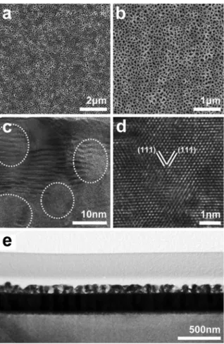
Using this solution as the electrolyte, the mesoporous Cu films were electrodeposited on a conductive Au-coated Si(Au-Si) wafer at a constant voltage of @0.4 V at room temperature and without stirring (see Supporting Information for additional details on the electrochemistry setup). The PS-b-PEO was completely removed by ultraviolet ozone treat-ment. Scanning electron microscopy (SEM) micrographs show that the top side of the film is composed of uniformly distributed mesopores (Figure 1a,b and Figure S1). The entire area of the film is homogenous and free of any defects such as perforations or bumps. According to SEM, the average pore size is about 48 nm, with a wall thickness of approximately 65 nm (Figure 1b and Figure S1). Longer deposition times led to thicker films. But surprisingly no variation in the size and uniformity of the pores regardless of thickness was observed. This approach shows a fairly high repeatability in the porous constructions no matter the variations of the electrolyte batches, making it a robust method for large-area mesoporous coating, perhaps extend-ing to meter length scales (Figure S2).
A cross-sectional specimen sampled from the resulting mesoporous Cu film was further investigated by using trans-mission electron microscopy (TEM). Even in the earliest stages of deposition, the mesoporous structures formed on the Au-Si substrate (Figure 1e and Figure S3a). High-resolution TEM (HRTEM) images show that the Cu frameworks are highly crystalline without any amorphous domains, and clear lattice fringes extended unabridged from bottom to top of the film (Figure 1c and Figure S3b–c). The lattice fringes with a constant d spacing of 0.21 nm can be well ascribed to the (111) lattice planes of face-centered cubic (fcc) Cu crystals
(Figure 1d). The crystallinity of the obtained Cu film was then studied by wide-angle X-ray diffraction (XRD) carried out in in-plane mode with various incident angles, which is sensitive to the lattice planes that are perpendicular to the film surface. With an incident angle in the range of 0.5–1.588, the (220) diffraction peak ascribed to Cu fcc crystal is clearly observed, although a tiny intensity of other diffraction planes are observed (Figure S4). A deeper scanning to the Cu films at a higher incident angle (> 5.088) showed the diffraction peaks from the Au substrate. Thus, the in-plane XRD data shows the Cu crystals have a preferential orientation according to the (110) plane vertical to the substrate. In the case of one-dimensional (1D) Cu nanowires, previous reports have demonstrated a crystal growth along the h110i direction.[16]
The polymeric micelles play the central role in the fabrication of uniform mesoporous Cu films. Therefore, an investigation to the micellization process was conducted. In pure THF, the diblock copolymer, PS-b-PEO, is completely dissolved to be a clear solution without any micelles or aggregates (Figure 2a-i). The addition of ethanol and aqueous solution (CuSO4 and H2SO4) led to a cloudy solution
indicating the polymeric micelles, which was further evi-denced by the Tyndall effect in the electrolyte (Figure 2a-ii). It should be noted that the addition of CuSO4, caused the Scheme 1. a) Schematic illustration for the preparation process, and
b) the typical SEM image of the mesoporous Cu film.
Figure 1. a),b) SEM images of the top-surface of the mesoporous Cu films. c),d) Cross-sectional HRTEM images of the mesoporous Cu films. The pores are indicated by circles in panel (c). e) Low-magnifica-tion TEM image of the cross-secLow-magnifica-tion of the mesoporous Cu film.
micelles to aggregate slightly (Figure 2b,c and Figure S5) and decrease in diameter (from 36 nm to 28 nm; Figure S5). These observations indicate that the CuSO4 stimulated the
inter-action between the micelles.[5b]
Retaining the micelle structure during Cu deposition, which depends on the interaction between the micelles and the metal precursors, was vital to the templating of uniform mesopores. To understand the formation mechanism of mesoporous Cu, ultraviolet-visible-near infrared (UV/Vis-NIR) absorption measurements were carried out for the electrolyte solutions under our working conditions (Fig-ure 2d). Cu2+ions are readily complexed with water and the
peak at around 800 nm corresponds to a d–d transition of [Cu(H2O)6]2+ion (Figure 2d).[17]The other bands in the UV
region of the spectrum originate from various moieties of the surfactants, such as the benzene rings of the phenyl group of the surfactant. Cu2+ions in an octahedral field display a single
d–d transition from a2E
gground state to a2T2gexcited state.[17]
The tail on the low energy site is due to Jahn–Teller
distortion.[17] Although it is difficult to predict whether the
coordination sphere is water molecule interacting with the ethylene oxide moiety of the micelles through hydrogen bonding or surfactant oxygen of the ethylene oxide units, the dissolved Cu species should be 2+ charged. The d–d band
completely disappears upon electrochemical reduction pro-cess.
In the micelle solution, it is likely that the CuSO4
dissolved as [Cu(H2O)6]2+and SO42@ions and interact with
the ethylene oxide shell domains of the micelles.[18] We
consider that the Cu ions can be, in the solution, as free ions as well as in the hydrophilic domains of the micelles. The micelles with Cu species could be neutral, negatively or positively charged depending on the Cu2+/SO
42@ratios in the
micelles. Since reduction takes place at the cathode, the Cu2+
rich micelles (overall positively charged ones) and free [Cu(H2O)6]2+ions can be selectively directed to the cathode
surface, where the Cu2+ ions are reduced to the metallic
copper. The above formation mechanism satisfactorily explains the formation of mesopores in our self-assembly-reduction process.
The following chemical equilibrium [Eq. (1)] summarizes the assembly process, where “M” stands for micelle, (aq) species are free ions, and (n@m) can be negative or positive depending on the Cu2+/SO
42@ratios. CuSO4þ PS-b-PEO þ H2O !
½CuðH2OÞ6A2þðaqÞþ SO42@ðaqÞþ ½Mð½CuðH2OÞ6A2þÞnðSO42@ÞmA2ðn@mÞþ
ð1Þ
The addition of H2SO4takes a substantial role in obtaining
continuous mesoporous Cu films. In the absence of H2SO4,
only isolated Cu nanoparticles are confirmed on the substrate (Figure S6). By gradual increase the concentration of H2SO4,
the porous structures of the continuous Cu film become apparent. Further optimization of the technique led us to settle on a H2SO4 concentration of 156.25 mm (Figure S7).
Our method is distinctly different from previous reports that use H2SO4to create H2bubbles that direct the formation of
large-sized pores in the films.[14,19]In our method, H 2SO4has
two essential effects: 1) the addition of H2SO4 solution can
prevent a formation of hydroxides of Cu precursors,[20]which
can be well supported by the transparent solution with H2SO4
solution (Figure 2a-ii), while, in the absence of H2SO4, some
precipitates are formed at the bottom of the electrolyte (Figure 2a-iii); and 2) H2SO4increases the ionic conductivity
of the electrolyte, favoring a high deposition rate of Cu and the formation of continuous films. When the used acids were changed to other types, the quality of mesoporous structures was decreased (Figure S8).
The impact of H2SO4 on ionic conductivity can be
observed in the electrodeposition traces before and after addition of acid (Figure S9a). Without H2SO4, the cyclic
voltammetric (CV) curves show a very small and linear current response, suggesting the huge resistance of the electrolyte. Upon addition of H2SO4solution, the CV curve
showed two reduction processes that correspond to: Cu2+!
Cu+and Cu+!Cu0(Figure S9a). According to the Pourbaix
diagram, direct reduction of Cu2+ to Cu0 is possible by Figure 2. a) Optical micrographs demonstrating the emergence of the
Tyndall effect in the electrolyte solution with different compositions: a-i) PS-b-PEO dissolved in THF, a-ia-i) PS-b-PEO +CuSO4+ H2SO4, and
a-iii) PS-b-PEO + CuSO4. Typical TEM images of the polymeric micelles
b) before and c) after the addition of CuSO4precursor. The samples
are stained with 1.0 wt% phosphotungstic acid to highlight the micelles. d) UV/Vis-NIR spectra of different solutions: i) PS-b-PEO micelles+ CuSO4+ H2SO4, ii) CuSO4, iii) H2SO4, and iv) PS-b-PEO
micelles, respectively. (Note: to highlight the interactions among different compositions, UV/Vis-NIR spectra of low- and high- wave-lengths were obtained at different composition concentrations: low concentration for low-wavelength, and high concentration for high-wavelength.)
manipulating the reduction potential at such an acidic condition in the present study.[21]This excludes the possibility
for the formation of other Cu phases (e.g., Cu2O).
Addition-ally, the charge transfer resistance was further investigated at two different electrolytes. Without any doubt, the charge transfer resistance decreases dramatically upon the addition of H2SO4 (Figure S9b,c). We believe that this is the key to
preparing continuous Cu films with high reproducibility. The reduction rate of Cu species is also extremely important for the final mesoporous structures.[6a,8a,22]
Electro-chemical deposition enables the precise regulation of the crystal growth manner of the Cu walls that form around the micelles. Variations in the structure of the mesopores could be observed by using different constant potentials between @300 mV and @700 mV (Figure S10). From the top surface structures of the obtained films, it is obvious that the mesoporous structures are greatly changed, and optimized at particular potentials (i.e., @300 mV and @400 mV). A high reduction rate of Cu at relatively low potentials (e.g., @600 mV and @700 mV in the present work), affords extremely large sized Cu crystals at the initial stage, which then grow rapidly to exceed the size of the hydrophilic volume of the micelles, thus leading to films with inadequate porous structures (Figure S10d,e).[6a,9b]
The films with good mesoporous structures, that were prepared at three different potentials (i.e., @300 mV, @400 mV and @500 mV), were studied by cyclic voltammetry to sign light on how the accessible surface area depends on the applied constant potentials. The mesoporous Cu film pre-pared at @400 mV had the highest current density compre-pared to other films (Figure S11), indicating that the great advant-age of perfect mesoporous structures. A high deposition potential (@300 mV) resulted in a relatively slow reduction speed, and small nanocrystals are obtained on the surface of the films, as shown in the inset of Figure S11a. The formation of small nanocrystals caused by the slow deposition rate finally decreased the surface area of the porous film.
Non-enzymatic glucose sensors based on nanostructured Cu have been intensively studied owing to the material’s good conductivity, low cost, and superior performance. As a result of its self-supported mesoporous structures, mesoporous Cu film is a good candidate for the direct detection of glucose to satisfy the requirements of diverse applications by maximiz-ing the sensitivity and achievmaximiz-ing favorable selectivity. A highly improved activity and selectivity toward the glucose detection was realized by using the nanoporous Cu film, indicating an attractive application for the daily use. The details are given in Figure S12 and Table S1.
In summary, we have, for the first time, demonstrated the preparation of large-scale mesoporous Cu films based on a novel and simple approach to precisely balance the growth manner of the Cu frameworks and the micelle structures regardless the substrate variations. The present success not only indicates the capability of creating mesoporous struc-tures with highly crystalized metals, but also paves a new way for preparation of porous Earth-abundant metals for diverse applications and at low cost.
Acknowledgments
This work was partially supported by the Australian Institute for Innovative Materials (AIIM) Gold/2015 grant and the University of WollongongQs Global Challenge Program/2015 grant.
Keywords: copper · electrochemical deposition · mesoporous materials · micelles · soft-templates
How to cite: Angew. Chem. Int. Ed. 2016, 55, 12746–12750 Angew. Chem. 2016, 128, 12938–12942
[1] a) H. Zhang, X. Yu, P. V. Braun, Nat. Nanotechnol. 2011, 6, 277; b) C. V. Falub, H. von K-nel, F. Isa, R. Bergamaschini, A. Marzegalli, D. Chrastina, G. Isella, E. Mgller, P. Niedermann, L. Miglio, Science 2012, 335, 1330; c) X.-J. Wu, J. Chen, C. Tan, Y. Zhu, Y. Han, H. Zhang, Nat. Chem. 2016, 8, 470; d) B. Kong, J. Tang, Y. Zhang, T. Jiang, X. Gong, C. Peng, J. Wei, J. Yang, Y. Wang, X. Wang, G. Zheng, C. Selomulya, D. Zhao, Nat. Chem. 2016, 8, 171.
[2] a) K. Dietrich, D. Lehr, C. Helgert, A. Tgnnermann, E.-B. Kley, Adv. Mater. 2012, 24, OP321; b) M. H. Lee, H. Gao, J. Henzie, T. W. Odom, Small 2007, 3, 2029; c) A. R. Halpern, R. M. Corn, ACS Nano 2013, 7, 1755.
[3] a) J. Henzie, M. Grgnwald, A. Widmer-Cooper, P. L. Geissler, P. Yang, Nat. Mater. 2012, 11, 131; b) Y. H. Lee, W. Shi, H. K. Lee, R. Jiang, I. Y. Phang, Y. Cui, L. Isa, Y. Yang, J. Wang, S. Li, X. Y. Ling, Nat. Commun. 2015, 6, 6990; c) X. A. Zhang, B. Dai, Z. Xu, C.-H. Chang, Small 2015, 11, 1285.
[4] a) V. Malgras, H. Ataee-Esfahani, H. Wang, B. Jiang, C. Li, K. C.-W. Wu, J. H. Kim, Y. Yamauchi, Adv. Mater. 2016, 28, 993; b) S. C. Warren, L. C. Messina, L. S. Slaughter, M. Kamperman, Q. Zhou, S. M. Gruner, F. J. DiSalvo, U. Wiesner, Science 2008, 320, 1748; c) H. Wang, H. Y. Jeong, M. Imura, L. Wang, L. Radhakrishnan, N. Fujita, T. Castle, O. Terasaki, Y. Yamauchi, J. Am. Chem. Soc. 2011, 133, 14526; d) K.-S. Choi, E. W. McFar-land, G. D. Stucky, Adv. Mater. 2003, 15, 2018; e) V. Malgras, Q. Ji, Y. Kamachi, T. Mori, F. K. Shieh, K. C.-W. Wu, K. Ariga, Y. Yamauchi, Bull. Chem. Soc. Jpn. 2015, 88, 1171.
[5] a) Y. Yamauchi, K. Kuroda, Chem. Asian J. 2008, 3, 664; b) H. Wang, L. Wang, T. Sato, Y. Sakamoto, S. Tominaka, K. Miyasaka, N. Miyamoto, Y. Nemoto, O. Terasaki, Y. Yamauchi, Chem. Mater. 2012, 24, 1591; c) H. J. Shin, R. Ryoo, Z. Liu, O. Terasaki, J. Am. Chem. Soc. 2001, 123, 1246.
[6] a) G. S. Attard, C. G. Gçltner, J. M. Corker, S. Henke, R. H. Templer, Angew. Chem. Int. Ed. Engl. 1997, 36, 1315; Angew. Chem. 1997, 109, 1372; b) G. S. Attard, P. N. Bartlett, N. R. B. Coleman, J. M. Elliott, J. R. Owen, J. H. Wang, Science 1997, 278, 838.
[7] a) B. Jiang, C. Li, V. Malgras, M. Imura, S. Tominaka, Y. Yamauchi, Chem. Sci. 2016, 7, 1575; b) C. Li, T. Sato, Y. Yamauchi, Angew. Chem. Int. Ed. 2013, 52, 8050; Angew. Chem. 2013, 125, 8208; c) Y. Li, B. P. Bastakoti, V. Malgras, C. Li, J. Tang, J. H. Kim, Y. Yamauchi, Angew. Chem. Int. Ed. 2015, 54, 11073; Angew. Chem. 2015, 127, 11225; d) X. Teng, X. Liang, S. Maksimuk, H. Yang, Small 2006, 2, 249.
[8] a) C. Li, :. Dag, T. D. Dao, T. Nagao, Y. Sakamoto, T. Kimura, O. Terasaki, Y. Yamauchi, Nat. Commun. 2015, 6, 6608; b) S. Pedireddy, H. K. Lee, W. W. Tjiu, I. Y. Phang, H. R. Tan, S. Q. Chua, C. Troadec, X. Y. Ling, Nat. Commun. 2014, 5, 4947; c) M. K. Khristosov, L. Bloch, M. Burghammer, Y. Kauffmann, A. Katsman, B. Pokroy, Nat. Commun. 2015, 6, 8841.
[9] a) X. Huang, Y. Li, Y. Chen, E. Zhou, Y. Xu, H. Zhou, X. Duan, Y. Huang, Angew. Chem. Int. Ed. 2013, 52, 2520; Angew. Chem. 2013, 125, 2580; b) C. Li, B. Jiang, N. Miyamoto, J. H. Kim, V.
Malgras, Y. Yamauchi, J. Am. Chem. Soc. 2015, 137, 11558; c) C. Li, T. Sato, Y. Yamauchi, Chem. Commun. 2014, 50, 11753. [10] a) B. Lim, M. Jiang, P. H. C. Camargo, E. C. Cho, J. Tao, X. Lu,
Y. Zhu, Y. Xia, Science 2009, 324, 1302; b) B. Jiang, C. Li, M. Imura, J. Tang, Y. Yamauchi, Adv. Sci. 2015, 2, 1500112; c) H. Ataee-Esfahani, M. Imura, Y. Yamauchi, Angew. Chem. Int. Ed. 2013, 52, 13611; Angew. Chem. 2013, 125, 13856.
[11] M. Wang, L. Wang, H. Li, W. Du, M. U. Khan, S. Zhao, C. Ma, Z. Li, J. Zeng, J. Am. Chem. Soc. 2015, 137, 14027.
[12] a) D. Zhang, R. Wang, M. Wen, D. Weng, X. Cui, J. Sun, H. Li, Y. Lu, J. Am. Chem. Soc. 2012, 134, 14283; b) B. Thakur, E. Bernalte, J. P. Smith, C. W. Foster, P. E. Linton, S. N. Sawant, C. E. Banks, Analyst 2016, 141, 1233; c) H. Pang, Q. Lu, J. Wang, Y. Li, F. Gao, Chem. Commun. 2010, 46, 2010; d) C. W. Li, M. W. Kanan, J. Am. Chem. Soc. 2012, 134, 7231.
[13] X. Niu, Y. Li, J. Tang, Y. Hu, H. Zhao, M. Lan, Biosens. Bioelectron. 2014, 51, 22.
[14] a) H.-C. Shin, M. Liu, Chem. Mater. 2004, 16, 5460; b) Y. Li, W.-Z. Jia, Y.-Y. Song, X.-H. Xia, Chem. Mater. 2007, 19, 5758; c) J.-H. Kim, R.-J.-H. Kim, J.-H.-S. Kwon, Electrochem. Commun. 2008, 10, 1148.
[15] a) X. Huang, Y. Chen, C.-Y. Chiu, H. Zhang, Y. Xu, X. Duan, Y. Huang, Nanoscale 2013, 5, 6284; b) H. Guo, Y. Chen, H. Ping, J. Jin, D.-L. Peng, Nanoscale 2013, 5, 2394; c) G. Guisbiers, S. Mejia-Rosales, S. Khanal, F. Ruiz-Zepeda, R. L. Whetten, M. Jos8-Yacaman, Nano Lett. 2014, 14, 6718.
[16] a) A. R. Rathmell, S. M. Bergin, Y.-L. Hua, Z.-Y. Li, B. J. Wiley, Adv. Mater. 2010, 22, 3558; b) J. Song, J. Li, J. Xu, H. Zeng, Nano Lett. 2014, 14, 6298; c) Y. Zhao, Y. Zhang, Y. Li, Z. Yan, New J. Chem. 2012, 36, 130.
[17] A. B. P. Lever, Inorganic Electronic Spectroscopy, Elsevier, New York, 1968.
[18] :. C¸elik, :. Dag, Angew. Chem. Int. Ed. 2001, 40, 3800; Angew. Chem. 2001, 113, 3916.
[19] a) J. Liu, L. Cao, W. Huang, Z. Li, ACS Appl. Mater. Interfaces 2011, 3, 3552; b) J. Zhang, M. D. Barl, E. Pellicer, J. Sort, Nanoscale 2014, 6, 12490.
[20] R. van den Berg, C. F. Elkjaer, C. J. Gommes, I. Chorkendorff, J. Sehested, P. E. de Jongh, K. P. de Jong, S. Helveg, J. Am. Chem. Soc. 2016, 138, 3433.
[21] a) G. Recio, D. Gallach, M. M. Silv#n, K. Fukami, R. J. M. Palma, G. R. Castro, _. MuÇoz-Noval, J. Phys. Chem. C 2014, 118, 14905; b) A. Cuenca, J. Agrisuelas, J. J. Garc&a-JareÇo, F. Vicente, Langmuir 2015, 31, 12664.
[22] D. Grosso, C. BiossiHre, B. Smarsly, T. Brezesinski, N. Pinna, P. A. Albouy, H. Amenitsch, M. Antonietti, C. Sanchez, Nat. Mater. 2004, 3, 787.
Received: June 21, 2016