International Journal on Magnetic Particle Imaging Vol 6, No 2, Suppl 1, Article ID 2009064, 3 Pages
Proceedings Article
Design of a doubly tunable gradiometer coil
A. R. Cagil
1,2,∗·
B. Tasdelen
1,2·
E. U. Saritas
1,2,31Department of Electrical and Electronics Engineering, Bilkent University, Ankara, Turkey 2National Magnetic Resonance Research Center, Ankara, Turkey
3Neuroscience Program, Sabuncu Brain Research Center, Bilkent University, Ankara, Turkey ∗Corresponding author, email: [email protected]
©2020 Cagil et al.; licensee Infinite Science Publishing GmbH
This is an Open Access article distributed under the terms of the Creative Commons Attribution License (http://creativecommons.org/licenses/by/4.0), which permits unrestricted use, distribution, and reproduction in any medium, provided the original work is properly cited.
Abstract
In a magnetic particle imaging (MPI) scanner, utilizing a tunable gradiometer receive coil can aid in achieving greater degree of decoupling of direct feedthrough signal. However, such a coil can be hard to tune since a very precise positioning of the compensation segment is necessary for excellent decoupling. In this work, we present a doubly tunable gradiometer coil capable of fine tuning without loss of tuning range. We show with experimental results this design can achieve an effective 81.4 dB decoupling in comparison to an identical coil with no gradiometric compensation.
I Introduction
Due to the simultaneous excitation and reception in Mag-netic Particle Imaging (MPI)[1], the drive field (DF) di-rectly feeds through to the receive coil. This coupled direct feedthrough signal is usually orders of magnitude larger than the MPI signal from the magnetic nanopar-ticle (MNP). Due to the limited dynamic range of the analog-to-digital converter (ADC) of the receive chain, feedthrough signal must be decoupled to not saturate the ADC. A commonly utilized method to overcome this problem is winding the receive coil in a gradiometer con-figuration, where a portion of the receive coil windings are wound in reverse direction to cancel out the direct feedthrough signal. There is a reverse winding ratio that, in theory, perfectly decouples the transmit and receive coils. However, this ratio depends on many factors, and slight positioning errors in the windings can easily de-grade the performance of the gradiometer coil. Previous work on gradiometer coil design also addressed the issue of fine-tuning the decoupling of the drive/receive coils [2,3], but those designs came with a tradeoff of tuning range vs. sensitivity. In this work, we present a doubly
tunable gradiometer coil design, which features a high tuning sensitivity while retaining a wide tuning range.
II Materials and Methods
Field sensitivity of the finite-length DF coils in MPI de-crease as distance from the center of the coil along the z-axis increases. Tunable gradiometer configurations usually utilize this feature by allowing one of the gra-diometer segments to move along the bore axis, therefore achieving a variable cancellation on the induced direct feedthrough voltage. There are several factors determin-ing the effectiveness of this variable cancellation, such as the position, turn count, and length of the cancella-tion segment. The relacancella-tionships between these factors and the amount of decoupling achieved is quite nonlin-ear. Therefore, a finite-element approach is suitable for designing a gradiometer coil. However, there is a hard-to-strike balance in design of a gradiometer coil. Having a wide tuning range (i.e. the ability to compensate for a large set of changes in the system, such as imperfect placement of windings on DF and/or receive coils, imper-fections in manufacturing of components, or changes in
International Journal on Magnetic Particle Imaging 2
Figure 1:The proposed doubly tunable gradiometer coil de-sign. The position of the coarse-tuning segment is referenced to the DF coil, and the position of the fine-tuning segment is referenced to the coarse-tuning element via plastic screws.
temperature) conflicts with the ability to fine-tune with ease. In this work, we propose to overcome this problem by bisecting one of the gradiometer segments. As shown in Fig. 1, the segment closer to the coil center provides coarse tuning, allowing one to quickly locate the decou-pling region. The other segment provides the fine-tuning capability, to chase the perfect decoupling spot.
II.I COMSOL Simulations
As the gradiometer was to be used with our in-house FFP scanner, our scanner’s existing DF coil and copper shield parameters were transferred to COMSOL. Then, the dou-bly tunable gradiometer receive coil shown in Fig. 1 was simulated. The inner/outer diameters of this coil were selected to match our previous untunable gradiometer receive coil (din= 20 mm, dout= 23.7 mm). Important
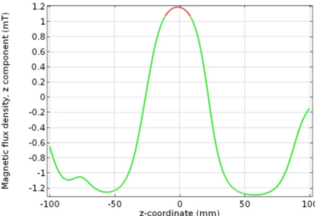
design parameters were the number of turns on each seg-ment, as they cannot be tuned after construction. The lengths of the segments were set to be proportional to the number of turns, assuming dense packing during wind-ing. The tunable parameters of the designed coil were the separation gaps of each tuning segment, resulting in a 2D “tuning parameter space”. COMSOL simulation had two goals: To find the parameters which provide a homogenous sensitivity profile (> 90 % homogeneity in> 12.5-mm region at the scanner isocenter) and a re-gion of excellent decoupling within the tuning parameter space. Design parameters were found with a combina-tion of grid search and manual adjustment. Resulting turn counts of fixed compensation segment, center re-ceive segment, coarse tuning segment, and fine-tuning segment were 83, 56, 55, and 28, respectively. The simu-lated sensitivity profile of the designed coil is shown in Fig. 2.
II.II Decoupling Experiments
Once the design parameters were set, a coil former to house the coil and the adjustment mechanism was de-signed in Fusion360 and 3D printed. The constructed gradiometer receive coil was inserted into the existing DF coil of our FFP scanner. Then, 9.7 kHz excitation pulses of 1 V amplitude were continuously applied to the DF coil, while the received signal was monitored in real time.
Figure 2: Sensitivity map of the proposed gradiometer coil. Shaded region in the center indicates the region with 90 % ho-mogeneity, measuring 19-mm in length at the center of 44 mm long receive segment. The small local peak at -75 mm is caused by the separation of the coarse and fine tuning segments.
Figure 3: A region in the tuning parameter space, showing several different levels of decoupling performance. Notice how the width of 80 dB decoupling region is about 25µm along the x-axis, while it is wider than 1 mm along the y-axis. This feature makes it easy to find the high decoupling region.
The feedthrough was minimized by adjusting both sep-arations via M3 size screws. The measured decoupling was evaluated by comparing the received signal to the signal in the absence of the compensation segments.
III Results and Discussion
III.I Simulation Results
A region of the tuning parameter space is shown in Fig-ure 3, which is a surface plot of the signal induced by the feedthrough on the receive coil for a sweep of both tuning separation parameters. Note that the width of the “-80 dB valley” is significantly greater (> 40x) along the y-axis than along the x-axis. This feature makes it easier to find and stay within the -80 dB valley. However, the decoupling in tuning parameter space is not always as
International Journal on Magnetic Particle Imaging 3
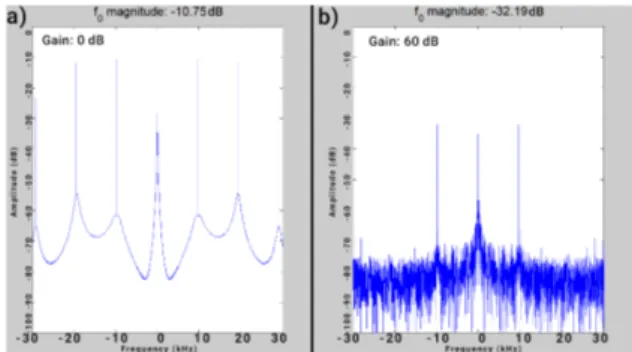
Figure 4:(a) Received spectrum of the reference coil with no compensation. Harmonics from the DF chain and transient artifacts are visible. (b) Received spectrum of the constructed and doubly tuned gradiometer coil. Artifacts and harmonics are well suppressed along with excellent decoupling of 81.4 dB with respect to the reference coil.
well behaved as in Fig. 3, due to imperfections. In that case, an estimate location for the well-behaving region can be found using a secondary simulation study.
III.II Experimental Results
Figure 4 shows the spectrum from the reference coil and the doubly tuned gradiometer coil, achieving -81.4 dB of decoupling with respect to the reference coil. After fine-tuning of the coil, an amplification of the direct feedthrough signal was needed to measure it. The signal amplitude of -32.1 dB shown in Fig. 4b was in the case of a gain of 1000 (i.e., 60 dB, confirmed experimentally) on the low-noise preamplifier. Considering -10.7 dB sig-nal on the reference coil with unity gain, and -92.1 dB corrected signal on the designed coil, we deduce that the proposed coil achieves 81.4 dB decoupling with re-spect to the reference coil. In Fig. 4, it can be seen that any higher harmonics arising from nonlinearities in the
DF chain that are present in the reference spectrum are also suppressed, along with the direct feedthrough at the fundamental frequency. The vibrations due to Lorentz forces during the drive field did not move the coil out of tuning.
IV Conclusions
In this work, we have shown that a doubly tunable gra-diometer coil makes the tuning process easier, without loss of a wide tuning range capability. The proposed coil achieved 81.4 dB decoupling when compared to an identical coil with no gradiometric compensation, and has also helped suppress higher harmonics arising from nonlinearities in the DF chain.
Author’s Statement
Research funding: This work was supported by the Sci-entific and Technological Research Council of Turkey (TUBITAK 115E677, 217S069). Conflict of interest: Au-thors state no conflict of interest.
References
[1] B. Gleich and J. Weizenecker, Tomographic Imaging Using the Non-linear Response of Magnetic Particles, Nature, 435(7046):1217- 1217, 2005. doi: 10.1038/nature03808.
[2] Z. W. Tay, P. W. Goodwill, D. W. Hensley, L. A. Taylor, B. Zheng, and S. M. Conolly, A High-Throughput, Arbitrary-Waveform, MPI Spectrome-ter and RelaxomeSpectrome-ter for Comprehensive Magnetic Particle Optimiza-tion and CharacterizaOptimiza-tion Scientific Reports, vol. 6, no. 1, Sep. 2016. doi: 10.1038/srep34180
[3] D. Pantke, N. Holle, A. Mogarkar, M. Straub, and V. Schulz, Multi-frequency magnetic particle imaging enabled by a combined passive and active drive field feed-through compensation approach, Medical Physics, vol. 46, no. 9, pp. 4077–4086, Jul. 2019.