2284
|
wileyonlinelibrary.com/journal/mrm © 2019 International Society for Magnetic Resonance Magn Reson Med. 2020;83:2284–2292. in MedicineN O T E
RF heating of deep brain stimulation implants in open‐bore
vertical MRI systems: A simulation study with realistic device
configurations
Laleh Golestanirad
1,2|
Ehsan Kazemivalipour
1,3,4|
David Lampman
5|
Hideta Habara
6|
Ergin Atalar
3,4|
Joshua Rosenow
7|
Julie Pilitsis
8|
John Kirsch
9 1Department of Radiology, Feinberg School of Medicine, Northwestern University, Chicago, Illinois2Department of Biomedical Engineering, McCormick School of Engineering, Northwestern University, Evanston, Illinois 3Department of Electrical and Electronics Engineering, Bilkent University, Ankara, Turkey
4National Magnetic Resonance Research Center (UMRAM), Bilkent University, Ankara, Turkey 5Hitachi Healthcare Americas, Twinsburg, Ohio
6Hitachi, Ltd. Healthcare Business Unit, Tokyo, Japan
7Department of Neurological Surgery, Feinberg School of Medicine, Northwestern University, Chicago, Illinois 8Department of Neurosurgery, Albany Medical Center, Albany, New York
9A.A. Martinos Center for Biomedical Imaging, Massachusetts General Hospital, Boston, Massachusetts
Correspondence
Laleh Golestanirad, Department of Radiology, Feinberg School of Medicine, Northwestern University, 737 N Michigan Ave, Suite 1600, Chicago, IL 60611. Email: [email protected] Funding information
National Institutes of Health, Grant/ Award Numbers: NIH R00EB021320, R03EB024705, and R03EB025344.
Purpose: Patients with deep brain stimulation (DBS) implants benefit highly from
MRI, however, access to MRI is restricted for these patients because of safety hazards associated with RF heating of the implant. To date, all MRI studies on RF heating of medical implants have been performed in horizontal closed‐bore systems. Vertical MRI scanners have a fundamentally different distribution of electric and magnetic fields and are now available at 1.2T, capable of high‐resolution structural and functional MRI. This work presents the first simulation study of RF heating of DBS implants in high‐field vertical scanners.
Methods: We performed finite element electromagnetic simulations to calculate
specific absorption rate (SAR) at tips of DBS leads during MRI in a commercially available 1.2T vertical coil compared to a 1.5T horizontal scanner. Both isolated leads and fully implanted systems were included.
Results: We found 10‐ to 30‐fold reduction in SAR implication at tips of isolated
DBS leads, and up to 19‐fold SAR reduction at tips of leads in fully implanted sys-tems in vertical coils compared to horizontal birdcage coils.
Conclusions: If confirmed in larger patient cohorts and verified experimentally, this
result can open the door to plethora of structural and functional MRI applications to guide, interpret, and advance DBS therapy.
K E Y W O R D S
deep brain stimulation, finite element method (FEM), interventional MRI, medical implants, MR‐guided neurosurgery, MRI safety, open‐bore MRI, RF heating, vertical MRI
1
|
INTRODUCTION
Deep brain stimulation (DBS) is a neurosurgical procedure that uses an implantable pulse generator (IPG) in the chest to send electric pulses via subcutaneous leads to specific nuclei in the brain to modulate their behavior. DBS has Food and Drug Administration (FDA) approval for treatment of Parkinson’s disease,1 and new studies show its efficacy for
an expanding range of neurologic and psychiatric disor-ders.2-5 There is a consensus that meticulous application of
neuroimaging, both for target verification and postoperative monitoring of stimulation effects, is essential to rule out com-plications, interpret clinical outcomes, and design enhanced therapeutic protocols.6 When investigating the
neuromodula-tory effects of DBS, neuroimaging studies have largely used PET or single photon emission tomography.7-10 MRI has
clear advantages over both PET and single photon emission tomography because of its excellent soft‐tissue contrast, non‐ invasive nature and the richness of post‐processing analytical methods that are available to use. The clinical community, however, has been cautious in adopting MRI for DBS pa-tients because of safety concerns associated with RF heating of implants. The major safety hazard is the “antenna effect,” where the electric field of MRI transmit coil induces RF cur-rents on implanted wires, leading to an increase in the spe-cific absorption rate (SAR) of energy deposition in the tissue. Serious injuries have underscored the severity of such RF heating.11 Consequently, the conditions under which DBS
pa-tients are indicated for MRI are limited. For example, under current guidelines, either the whole‐head SAR of the pulse sequence should be <0.1 W/kg (30 times below the FDA limit for imaging in the absence of implant) or the RMS of
B+1 field should be <2 µT, a limit well surpassed in most
clin-ical applications.12,13 Current MR labeling of DBS devices,
however, is limited to horizontal (closed‐bore) MRI systems. Vertical MRI scanners originally introduced as “open” low‐ field MRI systems are now available at 1.2T. To date, no DBS SAR literature exists for this class of scanners, which are now
available at field‐strengths capable of high‐resolution struc-tural and functional studies. Vertical MRI scanners have 90° rotated coils that generate a fundamentally different electric and magnetic field distribution. It is well established that the orientation and phase of MRI incident electric field along the trajectory of elongated implants plays an important role in determining the magnitude of SAR amplification around ex-posed tips of the implant.14-19 Therefore, this class of MRI
scanners may offer a whole new solution to the problem of safe DBS imaging that has not been yet investigated.
This work presents the first simulation study of RF heating of DBS implants in vertical MRI scanners. Patient‐ derived models of DBS systems representing 3 major clinical device configurations were constructed from patient imaging data and simulated in a commercial open‐bore 1.2T MRI sys-tem (OASIS, Hitachi Healthcare Americas, OH USA) and a horizontal 1.5T body birdcage. We found up to 30‐fold re-duction in SAR amplification at tips of DBS leads during RF exposure in vertical coil compared to a horizontal birdcage in both isolated and fully implanted DBS systems.
2
|
METHODS
2.1
|
Patient models
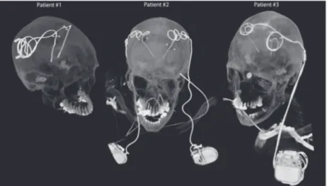
DBS surgery is typically performed in 2 stages. In the first stage, leads are implanted in targeted brain nuclei, and the other end of the lead is tucked under the scalp for later con-nection to the neurostimulator (Figure 1, patient 1). MRI at this stage is useful to rule out complications and to verify the target. In the next stage, an IPG is implanted in the chest and leads are connected to the IPG via subcutaneous extensions (Figure 1, patients 2 and 3). Patients may receive 2 single‐ channel IPGs implanted bilaterally in the pectoral region, each stimulating 1 lead (Figure 1, patient 2), or 1 double‐ channel IPG to stimulate both left and right leads (Figure 1, patient 3). The majority of DBS patients who need MRI for clinical assessment have fully implanted devices. MRI of
FIGURE 1 Postoperative CT images of patients with isolated and fully implanted DBS systems used in simulations
fully implanted DBS systems is also highly desired to per-form functional studies that investigate changes in patterns of brain activation as a function of stimulation parameters.20,21
To account for major clinically relevant DBS configura-tions, we simulated 1 representative patient of each category. Secondary use of imaging data for simulation and modeling was approved by the ethics review board of Northwestern University and by the Institutional Review Board at Albany Medical College. Postoperative CT images of 3 patients who had gone through subthalamic nucleus (STN) DBS surgery were used to reconstruct 3D trajectories of the implants. Lead trajectories were extracted from post‐operative CT im-ages and 3D models of leads, extensions, and pulse gener-ators were constructed following a procedure described in our previous works.18,22,23 Briefly, an image segmentation
tool (Amira, Thermo‐Fisher Scientific, Waltham, MA) was used to extract the hyper‐dense trajectory of DBS implants
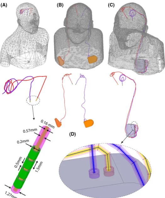
using a thresholding algorithm and preliminary 3D surfaces of the leads, extensions, and IPGs were constructed. The 3D surfaces were exported to a computer‐aided design tool (Rhino3D, Robert McNeal and Associates, Seattle, WA) in which lead trajectory lines were manually reconstructed and models of electrode contacts, core, insulation, and the IPG were created around them. Figure 2 shows patient models and implant details as used in finite element simulations.
Leads were composed of 4 cylindrical electrode contacts connected through a solid straight core made of platinum‐ iridium (Pt:Ir σ = 4 × 10⁶ S/m), encapsulated in a urethane
insulation (D = 1.27 mm, εr = 3.5) with an air‐filled lumen
(D = 570 µm). The IPG was modeled as a solid box of platinum‐iridium. There was a 0.5 mm gap between the end of the metal core of the extension cable and the conductive face of the IPG, representing an open circuit. Homogeneous body models (εr = 80, σ = 0.47 S/m) were constructed from
silhouettes of patients 2 and 3 based on CT images. For pa-tient 1, who did not have head and neck CT available, we registered DBS lead models to a standard homogeneous body model of head and upper chest.
2.2
|
RF coils and field calculations
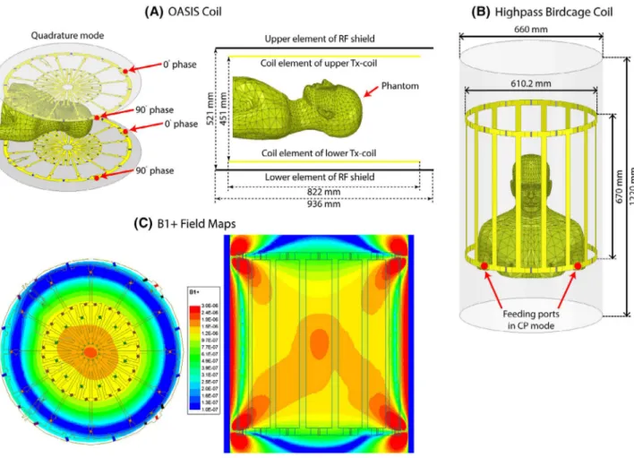
Models of a 12‐rung radial flat vertical birdcage coil tuned to 50.35 MHz (1.2T) and a generic horizontal birdcage tuned to 64 MHz (1.5T) were constructed and used in simu-lations. The vertical coil was designed based on a commer-cial coil (Oasis, Hitachi Healthcare) described in Suzuki et al.24 Figure 3 gives geometric details of the coil models,
as well as plots of their magnetic field on a central coronal plane passing through the body of patient 1 in the absence of the implant. The counter clockwise rotating component of the magnetic field vector was calculated as
B+
1=0.5 (Bx+jBy). The transmit efficiency was calculated
for both coils when loaded with a human body phantom without the implant as �
�
�B
+ 1���∕
√
P, in which P was the power
dissipated in the human body.
For all simulations, the input power of coils was adjusted to generate an average B+1= 2μT on an axial circular plane
(radius = 50 mm) positioned 20 mm below the distal tip of DBS implants. The location of this plane was chosen to allow an unbiased averaging of B+1 for both coils free of implant‐
induced distortion. 1g‐averaged SAR (SAR1g) was calcu-lated using HFSS built‐in SAR module that implements IEEE STD P1528.4 recommendation.25 The maximum of SAR1g
was recorded inside a cubic area of 20 mm × 20 mm × 20 mm surrounding 4 electrode contacts of the lead and used to compare 2 coils. Simulations were performed using ANSYS Electronics Desktop (HFSS 19.2.0, Designer, ANSYS, Canonsburg, PA).
2.3
|
Incident electric field
Recently, we demonstrated that the magnitude of the tan-gential component of MRI electric field along the first few centimeters of extracranial trajectory of DBS leads can be used as a predictor of severity of SAR amplification at elec-trode tips.18 This observation was not surprising, considering
incident electric field is responsible to induce RF currents on elongated conductive leads that eventually dissipate in the tissue and cause heating. To compare the orientation of the incident electric field of horizontal birdcage coils versus
FIGURE 3 Geometry of (A) a butterfly vertical coil based on a commercially available prototype (OASIS, Hitachi)24 and (B) a generic high‐ pass birdcage coil with dimensions reported in the literature.55 (C) B+
the vertical coil with respect to patients’ lead trajectories, we calculated the incident Etan along the length of leads and
ex-tensions using the method described in our previous work.18
In brief, we reran simulations without implant being present but with polylines representing leads and extension trajecto-ries imported to HFSS. We then extracted the unit tangent vectors along these lines (̂a) and calculated Etan (t) at each
point along the length of the lead as:
where ⃗E (t) is the incident electric field of the coil and ̂a is the
unit vector tangential to the lead’s trajectory.
3
|
RESULTS
The transmit efficiencies of the birdcage coil and the verti-cal Oasis coil loaded with a human phantom with no implant were 0.67 μT/√W and 0.51 μT/√W, respectively.
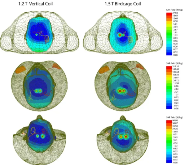
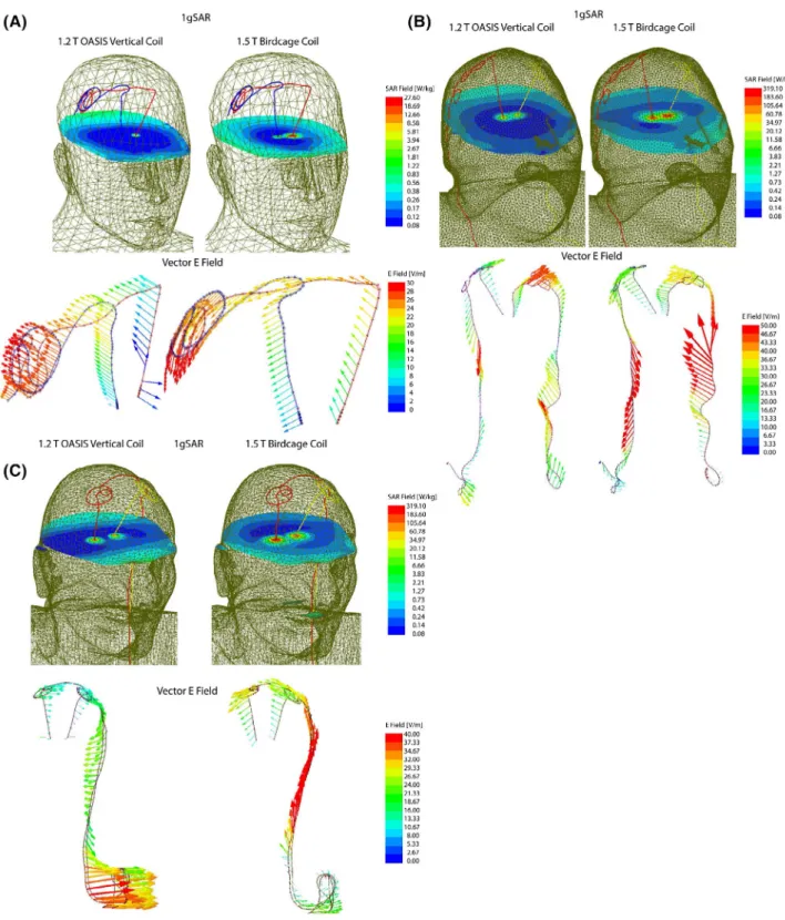
Figure 4 shows the distribution of local SAR around DBS lead tips of patients 1–3 for both vertical and birdcage body coils. Supporting Information Table S1 gives the maximum of 1g‐averaged SAR around tips of left and right DBS leads when the input power of both coils was adjusted to generate the same flip angle (B+1= 2μT) on a circular plane below the
tip of the leads. For patient 1 with isolated leads, SAR am-plification was reduced by 14‐fold and 30‐fold around tips of left and right DBS leads, respectively, when exposed to RF fields of the vertical coil compared to the birdcage coil.
A substantially higher local SAR amplification was ob-served around tips of DBS leads in patient 2 who had a fully implanted system with 2 bilateral IPGs. Compared to the birdcage coil, the vertical coil reduced the local SAR by 19‐fold SAR at the tip of left DBS lead and by 7‐fold SAR reduction at tip of right lead.
Patient 3 represented a special case where concentric loops were introduced in the trajectory of the leads to reduce SAR.18,22 This technique works by canceling out the effect
Etan(t) = ⃗E(t) ×̂a
FIGURE 4 1gSAR distributions in patients 1–3 on an axial plane passing through distal electrode contacts for the vertical coil (1.2T) and birdcage coil (1.5T). The input power of both coils is adjusted to produce a mean B+
1 = 2µT on a circular axial plane passing 20 mm below the
of tangential component of the electric field along opposite sides of the loop.18 Although, because of this surgical
modifi-cation, patient 3 already demonstrated a reduced SAR at tips of left and right leads in the birdcage coil, vertical coil still further reduced the SAR by 5‐fold at the tip of left lead and by 4‐fold at the tip of right lead.
Figure 5 illustrates the orientation of the incident elec-tric field vector along the trajectory of the leads in patient 1. As observed, the electric field of vertical coil along DBS leads is oriented in an anterior–posterior direction that is orthogonal to the trajectory of leads that roughly runs along medio–lateral direction on the scalp. In contrast, electric
FIGURE 5 1gSAR and the vector E field in patient 1 for birdcage coil and vertical coil. The orientation of E vector is orthogonal to the extracranial trajectory of the lead in the vertical coil, minimizing the induction of RF currents. The time evolution of E vector along the trajectory of the leads is given in the Supporting Information Data
field of the birdcage coil has a significant tangential com-ponent along the extracranial portion of the leads, inducing a strong virtual voltage on lead wired that in turn generate RF currents. The video in the supplementary data shows the evolution of incident electric field along trajectories of the implants in time.
4
|
DISCUSSION AND
CONCLUSION
During the past decade, DBS has developed into a remarkable treatment for major disabling neurologic and psychiatric dis-orders. MRI of DBS patients is extremely useful to rule out complications, assess comorbidities, and interpret therapeutic effects of the stimulation. The main obstacle in application of MRI in patients with DBS implants is the RF heating because of coupling of scanner’s electric fields with implanted leads. Such concerns have led many centers to refrain from per-forming MRI on DBS patients mainly because of difficulty of complying with industry‐proposed labeling of the device.26
In some cases, patients have faced the proposition of explant-ing their neurostimulator to receive a diagnostic MRI.27 The
past few years have witnessed a spike in efforts to alleviate the problem of MRI‐induced implant heating. The majority of works have been focused on modification of implant’s ge-ometry, structure, or material.28-37 Despite a spate of patents
filed over the past 2 decades, however, there is not a single MR‐safe DBS product available in the market, attesting to the fact that the problem of RF safety cannot be addressed by device manufacturers alone. In response, several groups have worked on MRI hardware modification to reduce the antenna effect by shaping and steering electric fields of scanners. Techniques based on parallel transmit pulse tailoring16,23,38-45
and reconfigurable MRI13,16,46-51 have shown promising
re-sults in phantoms studies at 1.5T and 3T, but such techniques require sophisticated hardware setup and high level exper-tise to deploy, and therefore their application is likely to be limited to research rather than everyday clinical use. Vertical MRI systems were originally introduced as open‐bore scan-ners offering an ideal platform for interventional procedures including direct DBS targeting with the help of intraopera-tive MRI. The current MR labeling of DBS devices, as well as the entirety of MRI studies on the RF heating of conduc-tive implants, has been limited to horizontal (closed‐bore) MRI systems. No DBS SAR literature exists for vertical MRI scanners that generate a fundamentally different electric and magnetic field distribution.
This work presents, for the first time, a computational study of RF heating around tips of DBS implants during MRI in a vertical open‐bore system at 1.2T and compares the re-sults with the SAR generated by a conventional 1.5T birdcage coil. Realistic models of DBS devices were constructed from
postoperative CT images of patients, representing 3 major clinically relevant device configurations. This included a patient with isolated bilateral leads, a patient with fully im-planted bilateral DBS leads stimulated via 2 single‐channel implantable pulse generators (IPGs) implanted in right and left pectoral regions, and a patient with fully implanted bi-lateral leads stimulated through 1 double‐channel IPG im-planted unilaterally. We found a significant reduction in SAR amplification (10‐ to 30‐fold) at the tips of implanted leads in the case of isolated bilateral leads, and a 4‐ to 19‐fold re-duction in SAR in case of fully implanted systems for vertical radial coil compared to the horizontal birdcage coil. A closer inspection of electromagnetic fields revealed that the orien-tation of incident electric field of vertical coil was mostly orthogonal to the trajectory of DBS leads, a criterion that we recently demonstrated to play a role in the severity of RF heating.18
The problem of MRI‐induced RF heating of medical im-plants is encountered in many other clinical applications. For example, integrated intracranial EEG (iEEG) with functional MRI is desired to elucidate mechanisms underlying the gen-eration of seizures, yet temperature rises up to 10°C has been reported in the tissue around iEEG electrode grids during MRI.52 Many patients with MR‐conditional cardiovascular
electronic devices happen to have retained cardiac leads, which are a contraindication for MRI.53,54 Our results also
encourage future studies to assess the RF heating of other types of elongated implants in vertical MRI systems.
ACKNOWLEDGMENTS
This work has been supported by NIH grant R03EB025344, R03EB024705, and R00EB021320.
CONFLICT OF INTEREST
Hideta Habara and David Lampman are employees of Hitachi.
ORCID
Laleh Golestanirad https://orcid.org/0000-0003-3869-6114 REFERENCES
1. US Food and Drug Administration. FDA executive summary: medtronic activa neurostimulator for dystonia treatment. https :// www.fda.gov/media/ 10329 1/download. Published March 7, 2017. 2. Schrock LE, Mink JW, Woods DW, et al. Tourette syndrome deep
brain stimulation: a review and updated recommendations. Mov
Disord. 2015;30:448–471.
3. Holtzheimer PE, Kelley ME, Gross RE, et al. Subcallosal cingulate deep brain stimulation for treatment‐resistant unipolar and bipolar depression. Arch Gen Psychiatry. 2012;69:150–158.
4. Sartorius A, Kiening KL, Kirsch P, et al. Remission of major de-pression under deep brain stimulation of the lateral habenula in a therapy‐refractory patient. Biol Psychiatry. 2010;67:e9–e11. 5. Malone DA, Dougherty DD, Rezai AR, et al. Deep brain
stimula-tion of the ventral capsule/ventral striatum for treatment‐resistant depression. Biol Psychiatry. 2009;65:267–275.
6. Horn A. The impact of modern‐day neuroimaging on the field of deep brain stimulation. Curr Opin Neurol. 2019;32:511–520. 7. Limousin P, Greene J, Pollak P, Rothwell J, Benabid AL,
Frackowiak R. Changes in cerebral activity pattern due to subtha-lamic nucleus or internal pallidum stimulation in Parkinson's dis-ease. Ann Neurol. 1997;42:283–291.
8. Jech R, Urgošík D, Tintěra J, et al. Functional magnetic resonance imaging during deep brain stimulation: a pilot study in four patients with Parkinson's disease. Mov Disord. 2001;16:1126–1132. 9. Stefurak T, Mikulis D, Mayberg H, et al. Deep brain stimulation
for Parkinson's disease dissociates mood and motor circuits: a func-tional MRI case study. Mov Disord. 2003;18:1508–1516.
10. Geday J, Østergaard K, Johnsen E, Gjedde A. STN‐stimulation in Parkinson's disease restores striatal inhibition of thalamocortical projection. Hum Brain Mapp. 2009;30:112–121.
11. Henderson JM, Tkach J, Phillips M, Baker K, Shellock FG, Rezai AR. Permanent neurological deficit related to magnetic resonance imaging in a patient with implanted deep brain stimulation elec-trodes for Parkinson's disease: case report. Neurosurgery. 2005; 57:E1063.
12. Medtronic. MRI guidelines for Medtronic deep brain stimulation sys-tems. http://manua ls.medtr onic.com/conte nt/dam/emanu als/neuro/ CONTR IB_228155.pdf. Published December, 1, 2015. Updated Month, day, year. Accessed Month, day, 2017.
13. Kazemivalipour E, Keil B, Vali A, et al. Reconfigurable MRI tech-nology for low‐SAR imaging of deep brain stimulation at 3T: ap-plication in bilateral leads, fully‐implanted systems, and surgically modified lead trajectories. NeuroImage. 2019;199:18–29. 14. Yeung CJ, Susil RC, Atalar E. RF heating due to conductive wires
during MRI depends on the phase distribution of the transmit field.
Magn Reson Med. 2002;48:1096–1098.
15. Nitz WR, Oppelt A, Renz W, Manke C, Lenhart M, Link J. On the heating of linear conductive structures as guide wires and catheters in interventional MRI. J Magn Reson Imaging. 2001;13:105–114. 16. Eryaman Y, Akin B, Atalar E. Reduction of implant RF heating
through modification of transmit coil electric field. Magn Reson
Med. 2011;65:1305–1313.
17. Rezai AR, Phillips M, Baker KB, et al. Neurostimulation system used for deep brain stimulation (DBS): MR safety issues and impli-cations of failing to follow safety recommendations. Invest Radiol. 2004;39:300–303.
18. Golestanirad L, Kirsch J, Bonmassar G, et al. RF‐induced heat-ing in tissue near bilateral DBS implants durheat-ing MRI at 1.5 T and 3T: the role of surgical lead management. NeuroImage. 2019; 184:566–576.
19. Golestanirad L, Rahsepar AA, Kirsch JE, et al. Changes in the spe-cific absorption rate (SAR) of radiofrequency energy in patients with retained cardiac leads during MRI at 1.5 T and 3T. Magn
Reson Med. 2019;81:653–669.
20. Sammarinto F, Krishna V, Rezai AR. MRI and fMRI for neuromodu-lation. In: Krames E, Peckham PH, Rezai AR, eds. Neuromodulation,
comprehensive textbook of principles, technologies, and therapies,
vol. 1. Cambridge: Academic Press; 2018:121–127.
21. Hancu I, Boutet A, Fiveland E, et al. On the (Non‐) equivalency of monopolar and bipolar settings for deep brain stimulation fMRI studies of Parkinson's disease patients. J Magn Reson Imaging. 2019;49:1736–1749.
22. Golestanirad L, Angelone LM, Iacono MI, Katnani H, Wald LL, Bonmassar G. Local SAR near deep brain stimulation (DBS) elec-trodes at 64 MHz and 127 MHz: a simulation study of the effect of extracranial loops. Magn Reson Med. 2017;78:1558–1565. 23. McElcheran CE, Golestanirad L, Iacono MI, et al. Numerical
sim-ulations of realistic lead trajectories and an experimental verifica-tion support the efficacy of parallel radiofrequency transmission to reduce heating of deep brain stimulation implants during MRI.
Nat Sci Rep. 2019;9:2124.
24. Ochi H, Soutome Y, Bito Y, Suzuki S, Shimoda T, Taniguchi T. inventors. High frequency coil for magnetic resonance imaging de-vice. Publisher Number WO/2008/108048. December 9, 2008. 25. IEC/IEEE International Standard. 2017. Determining the peak
spatial‐average specific absorption rate (SAR) in the human body from wireless communications devices, 30 MHz to 6 GHz ‐ Part 1: General requirements for using the finite‐difference time‐domain (FDTD) method for SAR calculations. In IEC/IEEE 62704‐1:2017 (pp. 1–86).
26. Tagliati M, Jankovic J, Pagan F, et al. Safety of MRI in patients with implanted deep brain stimulation devices. NeuroImage. 2009;47(S2):T53–T57.
27. Moeschler SM, Sanders RA, Hooten WM, Hoelzer BC. Spinal cord stimulator explantation for magnetic resonance imaging: a case series. Neuromodulation. 2015;18:285–288.
28. Denker S, Beutler A, Bulkes C, inventors. Kenergy Inc, assignee. MRI compatible implanted electronic medical device and lead. US Patent US8255054B2. May 10, 2007.
29. Atalar E, Allen J, Bottomley P, Eldelstein W, Karmarkar PV, inven-tors. Boston Scientific Neuromodulation Corp, MRI Interventions Inc, assignees. MRI‐safe high impedance lead systems. US Patent US8688226B2. October 20, 2006.
30. Olsen JM, Hrdlicka GA, Wahlstrand CD, Hoegh TB, inventors. Medtronic Inc, assignee. Lead electrode for use in an MRI‐safe im-plantable medical device. US Patent US7877150B2. January 25, 2011.
31. Villaseca E, Dublin G, inventors. Medtronic Inc, assignee. Electromagnetic trap for a lead. US Patent US20030144720A1. July 31, 2003.
32. Vase A, Sethna DN, inventors. Pacesetter Inc, assignee. Implantable medical lead configured for improved MRI safety. US Patent US20090270956A1. October 29, 2009.
33. Stevenson RA, Halperin HR, Lardo AC, et al, inventors. Greatbatch Ltd, assignee. Implantable lead bandstop filter employing an in-ductive coil with parasitic capacitance to enhance MRI compatibil-ity of active medical devices. US Patent US8903505B2. December 2, 2014.
34. Hoegh TB, Lo Bolea S, Wahlstrand CD, Hrdlicka GA, Olsen JM, in-ventors. Medtronic Inc, assignee. Lead electrode for use in an MRI‐ safe implantable medical device. US Patents US7877150B22007. January 25, 2011.
35. McCabe S, Scott J. A novel implant electrode design safe in the RF field of MRI scanners. IEEE Trans Microw Theory Tech. 2017;65:3541–3547.
36. Golestanirad L, Angelone LM, Kirsch J, et al. Reducing RF‐ induced heating near implanted leads through high‐dielectric
capacitive bleeding of current (CBLOC). IEEE Trans Microw
Theory Tech. 2019;67:1265–1273.
37. Serano P, Angelone LM, Katnani H, Eskandar E, Bonmassar G. A novel brain stimulation technology provides compatibility with MRI. Sci Rep. 2015;5:9805.
38. McElcheran CE, Yang B, Anderson KJ, Golenstani‐Rad L, Graham SJ. Investigation of parallel radiofrequency transmission for the re-duction of heating in long conductive leads in 3 Tesla magnetic resonance imaging. PLoS ONE. 2015;10:e0134379.
39. McElcheran CE, Yang B, Anderson KJ, Golestanirad L, Graham SJ. Parallel radiofrequency transmission at 3 Tesla to improve safety in bilateral implanted wires in a heterogeneous model. Magn
Reson Med. 2017;78:2406–2415.
40. Eryaman Y, Guerin B, Akgun C, et al. Parallel transmit pulse de-sign for patients with deep brain stimulation implants. Magn Reson
Med. 2015;73:1896–1903.
41. Wei PS, Yang B, McElcheran C, Golestanirad L, Graham SJ. Reducing radiofrequency‐induced heating in realistic deep brain stimulation lead trajectories using parallel transmission. In Proceedings of the 26th Annual Meeting of ISMRM, Paris, France, 2018. Abstract 0638.
42. McElcheran C, Golestanirad L, Graham S. Reduced heating of implanted electrical conductors using parallel radiofrequency transmission. In Proceeding of the 22nd Annual Meeting ISMRM, Milan, Italy, 2014. Abstract 0174.
43. McElcheran C, Golestanirad L, Iacono M, et al. Low heating B1 mapping in parallel transmit for deep brain stimulators. In Proceeding of the 25th Annual Meeting ISMRM, Honolulu, HI, 2017. Abstract 0482.
44. McElcheran C, Golestanirad L, Iacono M, et al. Parallel trans-mission for heating reduction in realistic deep brain stimulation lead trajectories. In Proceedings of the 25th Annual Meeting of ISMRM, Honolulu, HI, 2017. Abstract 2633.
45. McElcheran C, Golestanirad L, Graham S. Heating reduction in unilateral and bilateral implanted leads at 3T using parallel ra-diofrequency transmission in a heterogeneous head model. In Proceedings of the 24th Annual Meeting of ISMRM, Singapore, 2016. Abstract 3659.
46. Golestanirad L, Keil B, Iacono MI, et al. A patient‐adjustable MRI coil for implant‐friendly imaging of deep brain stimulation: de-sign, construction, and patient‐specific numerical simulations. In Proceedings of the 24th Annual Meeting of ISMRM, Singapore, 2016. Abstract 0354.
47. Eryaman Y, Turk EA, Oto C, Algin O, Atalar E. Reduction of the radiofrequency heating of metallic devices using a dual‐drive bird-cage coil. Magn Reson Med. 2013;69:845–852.
48. Golestanirad L, Keil B, Kirsch J, Pilitsis J, Wald LL. Reconfigurable coil technology can substantially reduce RF heating of bilateral deep brain simulation leads during MRI at 1.5 T: first in‐vitro studies with realistic implant trajectories. In Proceedings of the 27th Annual Meeting of ISMRM, Montreal, Canada, 2019. Abstract 0791.
49. Golestanirad L, Iacono MI, Keil B, et al. Construction and model-ing of a reconfigurable MRI coil for lowermodel-ing SAR in patients with deep brain stimulation implants. NeuroImage. 2017;147:577–588. 50. Golestanirad L, Keil B, Angelone LM, Bonmassar G, Mareyam A,
Wald LL. Feasibility of using linearly polarized rotating birdcage transmitters and close‐fitting receive arrays in MRI to reduce SAR in the vicinity of deep brain simulation implants. Magn Reson Med. 2017;77:1701–1712.
51. Golestanirad L, Kazemivalipour E, Keil B, et al. Reconfigurable MRI coil technology can substantially reduce RF heating of deep brain stimulation implants: first in‐vitro study of RF heating reduc-tion in bilateral DBS leads at 1.5 T. PLoS ONE. 2019;14:e0220043. 52. Carmichael DW, Thornton JS, Rodionov R, et al. Feasibility of
simultaneous intracranial EEG‐fMRI in humans: a safety study.
NeuroImage. 2010;49:379–390.
53. Golestanirad L, Rahsepar AA, Kirsch JE, et al. Changes in the spe-cific absorption rate (SAR) of radiofrequency energy in patients with retained cardiac leads during MRI at 1.5 T and 3T. Magn
Reson Med. 2019;81:653–669.
54. Golestanirad L, Rahsepar AA, Collins JC, et al. Safety of MRI on patients with abandoned/retained cardiac leads: patient‐derived simulation studies at 64MHz and 127MHz. In Proceedings of the 25th Annual Meeting of ISMRM, Honolulu, HI, 2017. Abstract 5456.
55. Yeo DT, Wang Z, Loew W, Vogel MW, Hancu I. Local SAR in high pass birdcage and TEM body coils for multiple human body mod-els in clinical landmark positions at 3T. J Magn Reson Imaging. 2011;33:1209–1217.
SUPPORTING INFORMATION
Additional supporting information may be found online in the Supporting Information section.
TABLE S1 Maximum 1g‐averaged SAR around tips of left
and right DBS leads in patients 1–3 for the 1.2T vertical OASIS coil and the 1.5T horizontal birdcage coil. The input power of both coils is adjusted to produce a mean B+
1 = 2µT
on a circular axial plane passing 20 mm below the electrodes
How to cite this article: Golestanirad L,
Kazemivalipour E, Lampman D, et al. RF heating of deep brain stimulation implants in open‐bore vertical MRI systems: A simulation study with realistic device configurations. Magn Reson Med. 2020;83:2284– 2292. https ://doi.org/10.1002/mrm.28049