PROCEEDINGS OF SPIE
SPIEDigitalLibrary.org/conference-proceedings-of-spieObservation of negative refraction
and negative phase velocity in true
left-handed metamaterials
Observation of negative refraction and negative phase velocity in true
left-handed metamaterials
Ekmel Ozbay
Nanotechnology Research Center, Bilkent University, Bilkent, 06800 Ankara, TURKEY
ABSTRACT
We report a true left-handed (LH) behavior in a composite metamaterial consisting of periodically arranged split ring resonator (SRR) and wire structures. The magnetic resonance of the SRR structure is demonstrated by comparing the transmission spectra of SRRs with that of closed SRRs. We confirmed experimentally that the effective plasma frequency of the LH material composed of SRRs and wires is lower than the plasma frequency of the wires. A well-defined left-handed transmission band with a peak value of -1.2 dB (–0.3 dB/cm) is obtained. We also report the transmission characteristics of a 2D composite metamaterial (CMM) structure in free space. At the frequencies where left-handed transmission takes place, we experimentally confirmed that the CMM structure has effective negative refractive index. Phase shift between consecutive numbers of layers of CMM is measured and phase velocity is shown to be negative at the relevant frequency range. Refractive index values obtained from the refraction experiments and the phase measurements are in good agreement. The experimental results agree extremely well with the theoretical calculations.
Keywords: Negative refraction, negative phase velocity, split ring resonator, left-handed medium, metamaterial
Veselago predicted that a medium with negative permittivity, ε, and negative permeability, µ, will exhibit negative indices of refraction [1]. When both the permittivity and the permeability are negative the electric field, the magnetic field and the wavevector components form a left-handed coordinate system, hence the name left-handed material (LHM) is used for description. Such a medium is expected to exhibit unusual physical properties such as negative refraction, reversal of Doppler shift, backward Cherenkov radiation. A medium with ε < 0 can easily be realized, e.g. by periodically arranged metallic wires [2]. On the other hand, the µ(ω) < 0 was a challenge due to lack of magnetic charge . Pendry et. al suggested that a periodic array of metallic split ring resonator (SRR) structures exhibit µ(ω) < 0 close to magnetic resonance frequency ωp [3]. This proposal brought the possibility of observing left-handed medium in to reality. Recently, this idea is brought to experimental investigation by constructing a composite metamaterial (CMM) consisting of two components which have ε(ω) < 0, a periodically arranged wire medium, and µ(ω) < 0, a periodically arranged SRR medium, simultaneously over a certain frequency range, respectively [4,5]. Various studies employing different structure designs extended this investigation [4-8]. Negative refraction of electromagnetic waves at the interface of CMMs is also observed [9-11] which supported the existence of a LHM. The parameters ε and µ can be obtained by a retrieval procedure from the numerically calculated transmission and reflection data for finite size CMMs [12,13], under the assumption of a homogeneous medium. This procedure confirmed [14] that a medium composed of SRRs and wires can indeed be characterized by effective ε and µ.
A medium transmits electromagnetic waves when both ε and µ have the same sign, i.e., both are negative or both are positive. If they have opposite signs the medium effectively reflects the incoming electromagnetic wave. The existence of a pass band for the CMM within the respective stop bands of SRR-only and wire-only mediums is intuitively considered as evidence for LH behavior. We experimentally demonstrate that the dielectric response of the CMM differs substantially from that of the wire-only medium, by measuring ωp for the CMM and wire-only structures. It is
evident that a shift in the plasma frequency renders the aforementioned intuitive approach inapplicable. This is a new feature that was not recognized in previous work. Based on this observation we present a new CMM structure which exhibits true left-handed behavior and has a transmission band with a peak value at -1.2 dB. To our knowledge, this is the highest transmission value reported for a LHM.
In general, a SRR structure exhibits both magnetic response [3] induced by the solenoidal currents flowing around the SRR, and electric response [15,16] by the dipole-like charge distribution along the incident electric field. The magnetic
(a)
—
(b) (C) C0
Cl) Cl) E CI-4
6 8 10 12 14Frequency (GHz)
response of the SRR structure exhibits a resonance in the transmission spectrum. This resonance behaviour is observed as a dip in the transmission spectrum of a single SRR structure. When SRRs are arranged in a periodic medium, due to the interaction between SRRs the resulting medium exhibits a band gap in the transmission spectrum. A bandgap in the transmission spectrum of periodic SRR medium may be due to negative ε or negative µ or solely due to the periodicity. This ambiguity can be resolved by using a structure in which the splits in the ring resonators are closed (CSRR). This will destroy the magnetic resonance but still keep the electric resonance. A gap present in SRR but not in CSRR will then correspond to µ<0.
Figure 1 :Schematics of (a) a single split ring resonator (SRR) (b) a ring resonator with splits closed (CSRR) (c) Periodic CMM composed of SRRs on one side, wires on the other side of dielectric board.
We fabricated SRR (Fig. 1.(a)) and CSRR (Fig. 1.(b)) structures by using standard printed circuit board technology. The structure parameters corresponding to Fig. 1 are as follows: d = t = 0.2 mm, w = 0.9 mm and r = 1.6 mm. The circuit board has a thickness 1.6 mm and dielectric constant of ε = 4.4. SRR units are arranged periodically with 5, 15, and 18 number of unit cells in x, y and z directions respectively. The unit cell consists of a single SRR with lattice constants ax = ay = 8.8 mm, and az = 6.5 mm. We performed free-space transmission measurements. The measurement setup consists of HP 8510C vector network analyzer and standard gain horn antennas for transmitting and receiving electromagnetic waves. The incident field propagates along the x direction with E, and H, along y and z directions, respectively.
Figure 2 :Measured transmission spectra of a periodic SRR medium (solid line) and periodic CSRR medium (dashed line) between 3-14 GHz.
C
0
U) U)E
U) C II \
'I
% I 4 5 6Frequency
8 7(GHz)
The measured transmission spectrum for SRR (solid line) medium and the CSRR (dashed line) medium are shown in Fig. 2. The transmission spectrum of the SRR medium exhibits two band gaps: the first band gap is between 3.55-4.05 GHz and the second band gap is between 8.1-11.9 GHz. The first band gap (3.55-4.05 GHz) of the SRR medium is not present in the CSRR medium, indicating µ < 0. Note that the second band gap, 8.1-11.9 GHz, is observed both in the transmission spectrum of the SRR and CSRR mediums. This measurement clearly shows that the stop bands of an SRR medium can not be automatically attributed to “negative µ” behaviour. Some of the observed gaps could also originate from the electrical response of the SRRs or from Bragg gaps due to periodicity.
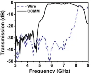
Figure 3 :Measured transmission spectra of wires (dashed line) and closed CMM (solid line) composed by arranging closed SRRs and wires periodically.
Another point to be discussed is the electric response of the CMM. Previously reported transmission results did not emphasize the interaction between SRR and wire structures. However, it was recently found [15] that the SRRs, in addition to their resonant magnetic response at ωm, exhibit a resonant electric response at ω0. The behavior is similar to that of a periodic cut-wire medium (wires of finite length) which exhibits a stop band with a well-defined lower edge due to the discontinuous wire geometry [8]. As a result, the SRRs contribute to the effective permittivity of the CMM, causing a downward shift on the plasma frequency determined solely from wire structures [15]. To demonstrate this effect, a CMM consisting of periodic alternating layers of CSRRs and wires is used (Fig. 1.(c)). Thickness, length and the width of the wires are 30 µm, 13.5 cm and 0.9 mm respectively. Figure 3 displays the measured transmission spectra of wire only medium and CMM consisting of CSRR and wire layers. The ωp of the wire-only structure around 8 GHz, is
reduced down to 5.3 GHz within the closed CMM structure. As seen in Fig. 3, ωp of the CMM is lower than that of the
wire-only medium alone. It is crucial to determine whether the shift in plasma cut-off frequency covers the magnetic resonance gap, which would render the CMM as a right-handed medium.
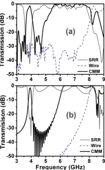
The experimental data presented in Fig. 3 clearly shows that one needs to take the shift in the plasma into account when designing mediums for LH behaviour. To observe true LH behaviour we designed the SRRs such that the first bandgap of SRR structure between 3.55 - 4.05 GHz is not obscured by the shift in plasma frequency. The CMM structure is made of Nx = 5, Ny = 15, and Nz = 24 unit cells. Each unit cell has a single SRR, and a copper wire from stacked SRR and wire layers, with lattice spacings ax = ay = 8.8 mm, az = 6.5 mm. The transmission spectra for SRR only (solid line), wire only (dashed line) and CMM (bold solid line) periodic structures are displayed in Fig. 4(a). The simulation results (Fig. 4.(b)) agree very well with the experimental data.
a
.
C0
U) U)E
U) CI-4
5
6 7 8Frequency (GHz)
Figure 4 :Transmission spectra of SRRs (solid line), wires (dashed line) and open CMM (bold solid line) (a) experiment (b) simulation.
The CMM structure allows propagation of EM waves between 3.6 and 4.1 GHz, where both ε and µ are negative. The CMM pass band exactly coincides with the stop band of SRR. The transmission peak at 3.9 GHz is -1.2 dB, which is a significantly high value for a material made of metals. Similarly, the simulations predict a transmission peak at 3.92 GHz of -1.5 dB. We stress that, a similar transmission band is not present for a CMM composed of CSRRs and wires (Fig. 3). The electric response contribution of SRRs is also evident here: If the ωp of the wire-only structure (dashed line in Fig. 4(a)) were used to identify the ε < 0 regime for the CMM, the transmission between 5.3 – 8 GHz would have occured in a regime with ε < 0 and µ > 0, which is not possible. However, as Fig. 3 suggests, the ε > 0 regime of the combined electric response of SRRs and wires start at 5.3 GHz.
Up to this point we concentrated on the transmission properties of metamaterial mediums consisting of SRR and wire structures. We demonstrated that a suitable combination of wires and SRRs exhibit true left-handed transmission peak in the transmission spectrum. Two very interesting properties of the LH medium are the negative refraction and the negative phase velocities. To investigate the negative refraction and negative phase velocities we studied the refraction and transmission phase properties of a 2 dimensional CMM medium.
The 2D CMM medium is fabricated by standard printed circuit board technology. The SRR and wire patterns are fabricated on the front and back sides of FR4 circuit boards which have 30 µm thick deposited copper layer. The length and width of the wire structures are l = 19 cm, and w = 0.9 mm, respectively. The unit cell consists of two SRRs and
(c)
iii,
13cm 70cm—SRR
——-Wire—CMM
C0
U) U)E
U) CI-Frequency (GHz)
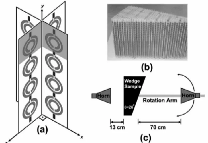
two wires in x-z planes, as shown in shaded parts of Fig. 5(a). The 2D CMM structure is made of Nx = 5, Ny = 20, and Nz = 40 unit cells, with lattice spacings ax = ay = az = 9.3 mm. Transmission measurements are performed in free space. Experimental measurement setup consists of a HP 8510C network analyzer, and a set of microwave horn antennas. The incident electromagnetic (EM) wave propagates along the x direction, while E is along y direction, and H is along z direction (Fig. 5(a)).
Figure 5 :(a) Schematics of 2D CMM structure (b) 2D Wedge CMM structure used for negative refraction experiment. (c) Schematic drawing of experimental setup used for refraction experiment.
Figure 6 shows the measured transmission spectra of periodic SRRs (solid line) and wires (dashed line) and 2D CMM between 3-7 GHz. As we have previously discussed, the bandgap of SRR between 3.55-4.05 GHz is due to magnetic resonance of periodic SRR medium, hence µ(ω) < 0 for this frequency range. The 2D CMM structure allows propagation of EM waves between 3.7 and 4.1 GHz, where both ε and µ are negative. The CMM pass band coincides with the stop band of SRR. The transmission peak at 3.92 GHz is -10.2 dB, which is significantly higher than the previously reported 2D CMM structures [5,11]. The transmission band starting from 5.3 GHz is due to downward plasma frequency shift, since the ε > 0 regime of the combined electric response of SRRs and wires starts at 5.3 GHz.
Figure 6 : Measured transmission spectra of a periodic SRR medium (solid line), periodic wire medium (dashed line) and 2D CMM medium (bold solid line) between 3-7 GHz.
We constructed a prism shaped 2D CMM structure for negative refraction. The actual structure is shown in Fig. 5(b). The minimum and maximum number of unit cells at the propagation direction is 3 and 19, which results in a wedge angle of θ = 26°. Fig. 5(c) depicts the schematic of the experimental setup. The source is 13 cm (~2λ) away from the first interface of the wedge. Receiver antenna is mounted on a rotating arm to obtain the angular distribution of the transmitted signal. Receiver antenna is located at a distance of 70 cm (~10λ) away from the second interface of the wedge. The distance from horn antenna to the prism structure was chosen in such a way that the near field effects are minimal.
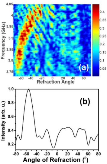
We scanned the angular refraction spectrum by ∆θ= 2.5° steps over a frequency range from 3.73 GHz to 4.05 GHz. Figure 7(a) shows the transmission spectrum as a function of frequency and refraction angle. The transmitted EM waves are refracted towards the negative side of the surface normal within the frequency range of 3.73 – 4.05 GHz. In contrast to the previous negative refraction experiments[9-11], the refraction index is measured to be negative for the entire LH transmission band. At lower frequencies the EM waves are refracted at higher negative refraction angles, which results in a higher negative refractive index. On the other hand the refraction index is lowered with increasing frequencies. By employing Snell’s law (nCMM sinθi = nair sinθr) an effective refractive index can be defined for the CMM. At f = 3.92 GHz, the incidence angle is θi = 26°, and EM wave is refracted at an angle of θr = 55° (Fig. 7(b)), then from Snell’s law we obtain neff = -1.87 ± 0.05 at 3.92 GHz.
ReTraction Angle
-80 -60 -40
-20 020 40 60
Angle of Refraction (°)
Figure 7 : (a) Transmission spectra as a function of frequency and refraction angle (b) The angular cross section of transmitted beam at f = 3.92 GHz.
The transmitted phase of CMMs is measured to investigate the phase velocity within both the left-handed (3.73-4.05 GHz) and right-handed (5.4-7.0 GHz) transmission bands (Fig. 6). Phase measurements are performed on rectangular slabs of CMMs, with various numbers of layers. Figure 8 shows the transmitted phase of CMMs (with varying number of layers) between frequencies 5.4-7.0 GHz, where CMM acts as a right-handed medium. As shown in Fig. 8, the phase of the transmitted EM wave increases, when a longer CMM is used, which is a typical right-handed behavior. On the other hand, increasing the number of layers decreases the phase of the transmitted EM wave at the left-handed frequency region (Fig.9). As shown in the inset of Fig.9, the average phase shift is negative for the relevant frequency range, which indicates that the phase velocity is negative.
Frequency (GHz)
Frequency (GHz)
Figure 8 :Unwrapped transmission phase data obtained from different lengths of CMM between 5.4 - 7.0 GHz, where right-handed transmission peak takes place. Inset: Average phase difference between consecutive numbers of layers of CMM. Phase shift is positive between 5.4 - 7.0 GHz.
Figure 9 :Unwrapped transmission phase data obtained from different lengths of CMM between 3.73 - 4.05 GHz, where left-handed transmission peak takes place. Inset: Average phase difference between consecutive numbers of layers of CMM. Phase shift is negative between 3.73 - 4.05 GHz.
One can find the value of refractive index by using the phase shift between consecutive numbers of layers of CMM. Phase velocity is defined as vph = c/n, and also given by vph = ω/k. Then, refraction index can be defined as n = k.c/ω, where k = ∆Φ/∆L. We then obtain the refraction index as:
ω
φ
c
L
n
∆
∆
=
(Eq. 1)At f = 3.92 GHz, the average phase shift between CMM layers is ∆Φ = -0.41 ± 0.05 π. By employing Eq.1, neff is obtained to be -1.78 ± 0.22, which is in good agreement with the value of -1.87 ± 0.05 obtained from the refraction experiment. For f = 3.98 GHz, neff obtained from the refraction experiment is found to be n = -2.02 ± 0.05, while the phase shift experiment gives n = -1.97 ± 0.22. Also at f = 3.84 GHz, the refraction experiment results (n = -1.22 ± 0.05), and the phase shift experiment results (n = -1.28 ± 0.21) are in good agreement. The measured phase velocity at 3.92 GHz is negative and equal to -0.51 c.
In conclusion, we have successfully demonstrated true left-handed behavior in free space with a high transmission peak. The left-handed transmission band exactly coincides with the region where both dielectric permittivity and magnetic permeability take negative values. By closing the splits of the SRRs, we experimentally verified the magnetic resonance
of the SRR structures. By using this procedure the regions of negative permeability and negative permittivity of SRR structures can be successfully identified. We also confirmed experimentally that the ωp of the CMM composed of SRRs and wires is lower than wires-only plasma frequency ωp which is essential for the design CMM structures and interpretation of transmission spectra. In addition, we have successfully demonstrated a left-handed transmission band for 2D CMM structure in free space with a high transmission peak. We experimentally confirmed that 2D CMM has negative refractive index at the entire left-handed frequency range (3.73-4.05 GHz). Phase shift and therefore phase velocity is shown to be negative, and the values of negative refractive indices obtained from the refraction experiments and the phase measurements are in good agreement.
ACKNOWLEDGMENTS
This work is supported by TUBITAK, EU-DALHM, EU-METAMORPHOSE, and EU-PHOREMOST. One of the authors (Ekmel Ozbay) acknowledges partial support from Turkish Academy of Sciences.
REFERENCES
1. V. G. Veselago, Sov. Phys. Usp. 10, 504 (1968).
2. J. B. Pendry et al., J. Phys.: Condens. Matter 10, 4785 (1998).
3. J. B. Pendry et al., IEEE Trans. Microwave Theory Tech. 47, 2075 (1999). 4. D. R. Smith et al., Phys. Rev. Lett. 84, 4184 (2000).
5. R. A. Shelby et al., Appl. Phys. Lett. 78, 480 (2001) 6. M. Bayindir et al., Appl. Phys. Lett. 81, 120 (2002). 7. K. Li et al., Appl. Phys. Lett. 82, 2535 (2003).
8. E. Ozbay et al., IEEE Trans. Antennas Propag. 51, 2592 (2003). 9. R. A. Shelby et al., Science 292, 77 (2001).
10. C. G. Parazzoli et al., Phys. Rev. Lett. 90, 107401 (2003). 11. A. A. Houck et al., Phys. Rev. Lett. 90, 137401 (2003).
12. P. Markos, and C. M. Soukoulis, Phys. Rev. E 65, 036622 (2002); P. Markos et al., Phys. Rev. E 66, 045601 (2002).
13. P. Markos and C. M. Soukoulis, Optics Express 11, 649 (2003); Optics Letters 28, 846 (2003)
14. D. R. Smith et al., Phys. Rev. B 65, 195104 (2002); T. Koschny et al., Phys. Rev. E 68, 065602 (2003). 15. T. Koschny, M. Kafesaki, E. N. Economou and C. M. Soukoulis, (unpublished).
16. N. Katsarakis et al., Appl. Phys. Lett. 84, 2943 (2004). *ozbay@fen.bilkent.edu.tr


