Full Terms & Conditions of access and use can be found at
http://www.tandfonline.com/action/journalInformation?journalCode=tewa20
Download by: [Bilkent University] Date: 29 September 2017, At: 04:40
Journal of Electromagnetic Waves and Applications
ISSN: 0920-5071 (Print) 1569-3937 (Online) Journal homepage: http://www.tandfonline.com/loi/tewa20
Radiation Properties and Coupling Analysis of a
Metamaterial Based, Dual Polarization, Dual Band,
Multiple Split Ring Resonator Antenna
K. B. Alici , A. E. Serebryannikov & E. Ozbay
To cite this article: K. B. Alici , A. E. Serebryannikov & E. Ozbay (2010) Radiation Properties and Coupling Analysis of a Metamaterial Based, Dual Polarization, Dual Band, Multiple Split Ring Resonator Antenna, Journal of Electromagnetic Waves and Applications, 24:8-9, 1183-1193, DOI: 10.1163/156939310791586188
To link to this article: http://dx.doi.org/10.1163/156939310791586188
Published online: 03 Apr 2012.
Submit your article to this journal
Article views: 128
View related articles
RADIATION PROPERTIES AND COUPLING ANALYSIS OF A METAMATERIAL BASED, DUAL POLARIZATION, DUAL BAND, MULTIPLE SPLIT RING RESONATOR ANTENNA
K. B. Alici
Nanotechnology Research Center, Department of Physics Department of Electrical and Electronics Engineering Bilkent University
Bilkent, Ankara 06800, Turkey
A. E. Serebryannikov
Hamburg University of Technology Hamburg D-21071, Germany
E. Ozbay
Nanotechnology Research Center, Department of Physics Department of Electrical and Electronics Engineering Bilkent University
Bilkent, Ankara 06800, Turkey
Abstract—We demonstrate an electrically small antenna that
operates at two modes, which correspond to two orthogonal polarizations. The antenna was single fed and composed of perpendicularly placed metamaterial elements and a monopole. One of the metamaterial elements was a multi split ring resonator (MSRR), and the other one was a split ring resonator (SRR). The elements’ physical sizes were the same while the electrical sizes differed nearly by 1 GHz. This variety resulted in the dual mode operation at the 4.72 GHz and 5.76 GHz frequencies. When the antenna operated in the MSRR mode at 4.72 GHz for one polarization, it simultaneously operated for the SRR mode at 5.76 GHz, but for the perpendicular polarization. The efficiencies of the modes were 15% and 40%, and electrical sizes were λ/11.2 and λ/9.5, correspondingly. Finally, we numerically demonstrate the effect of coupling of the two resonators on the operation frequencies.
Corresponding author: K. B. Alici ([email protected]).
1. INTRODUCTION
Electronic devices utilizing antennas are limited in physical size as determined by the size of the incorporated antenna. The characteristic dimensions of the antennas are directly proportional to their operation wavelength (λ), and they should have an electrical size approximately equal to λ/2 for efficient radiation. The metamaterial study has brought new opportunities to improve the performance of current devices [1–15]. In particular, the possibility of antenna miniaturization by utilizing metamaterials has been studied and proven to be useful by many researchers. Buell et al. experimentally demonstrated an efficient method for antenna miniaturization by loading a patch antenna with a resonator medium. Miniaturization factors of 4 to 7 with antenna efficiencies of 20% to 35% were achieved [16].
Miniaturization of a simple monopole antenna can be achieved by coupling it to a sole subwavelength metamaterial element instead of a medium. Alici et al. demonstrated a λ/10 monopole split ring resonator (SRR) composite antenna operating with 43% efficiency at 3.62 GHz [17]. The electrical size of the resonator can be reduced by increasing its quasi-static capacitance, leading to an electrically smaller antenna. The fundamental limit of this method was also studied, and it was shown that the antenna gain, and thereby efficiency, starts to decrease after some point [18]. One of the advantages of electrically small split ring resonator antennas (ESSRRA) is that their operation frequency can be as large as several hundred THz, as determined by the resonance frequency of the metamaterial elements available. As we scale the physical dimensions of the resonator, its operation frequency changes accordingly. A detailed analysis on the resonator performance was given in Refs. [19, 20], which includes the substrate effects and tunability of multi ring structures. The electrical size of a multi split ring resonator (MSRR) can be arranged by simply changing the number of its rings while retaining the physical size. In the present study, we utilized this property of MSRRs in order to create an ESSRRA that contains two different resonators and operates at two frequency bands. Hence, the suggested ESSRRA is distinguished from those in [17, 18], where a single resonator has been utilized. The polarizations of the antenna radiation are orthogonal for the two operation bands, one of which appears due to the MSRR, while the other one appears due to the SRR.
An antenna’s electrical size ‘u’ at the operation wavelength ‘λ0’ is defined by using the diameter (2a) of the minimum sphere that encloses it, i.e., u = (λ0/2a)λ. For the case of an antenna above a conducting plane, the radius of the minimum sphere is defined by
taking into account the antenna’s image [21]. It has been known since the 1940s that for a given antenna quality factor, the size of a passive small antenna is theoretically limited [22, 23]. In other words, the minimum quality factor (Qmin) depends on the minimum radius (a) and operation wavelength (λ0). The minimum quality factor is estimated by the formula: Qmin = (2k3a3)−1 + (ka)−1, where the wavevector is k = 2π/λ. In addition to the fundamental limit in the
Q-factor, the maximum achievable gain (G) for a given wavevector
(k) and minimum radius (a) are also theoretically limited. Fante numerically plotted the maximum of G/Q with respect to ka [24]. The limit for the theoretical gain of the antenna under test can be estimated from this data.
2. ANTENNA CONFIGURATION AND EXPERIMENTAL CHARACTERIZATION
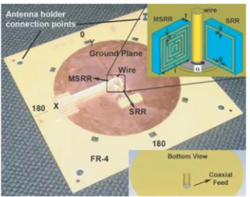
An antenna under test (AUT) can be experimentally characterized by using a network analyzer. In order to measure the scattering parameters (S-parameters), the AUT was connected to one of the network analyzer ports. We measured the necessary S-parameters (S11 and S21) with respect to a 50 Ω load, by using an HP8510C network analyzer and standard gain horn antennas. After a full two port calibration, we connected the ESSRRA and recorded its input reflection coefficient with the output port terminated with a matched load. The configuration of the AUT with the selected parameters is shown in Fig. 1. We loaded the monopole antenna simultaneously with two electrically small metamaterial elements. We placed the SRR composed of a single split ring parallel to the yz-plane. We had the MSRR with the same side length in the xz-plane, the number of rings (N ) of the MSRR was N = 5. The remaining parameters were the following: resonator side length, l = 4 mm, separation between the rings, s = 0.2 mm, width of the strips, w = 0.2 mm, split width,
g = 0.2 mm, thickness of the deposited metal (not shown in Fig. 1), h = 0.018 mm, substrate (FR-4) thickness, t = 1 mm. The listed
relative permittivity of FR-4 in CST library was εr = 4.9 with a dissipation factor tan δ = 0.02. The coaxial SMA connector was soldered to the ground plane from the bottom and the metamaterial particles were mechanically connected to the ground plane by using comb shaped FR-4 holders. We connected the antenna to an antenna holder from the corners of the ground plane for the characterization measurements.
The minima of the S11magnitude show us at which frequencies the antenna is matched to free space. These frequencies are the operation center frequencies. In Fig. 2, they are nearly equal to 4.74 GHz (MSRR
Figure 1. Antenna photograph
and geometry of the loading resonators.
Figure 2. Return loss (|S11|) of the antenna in logarithmic scale.
Table 1. Figures of merit extracted from the return loss (|S11|) data.
Freq. (GHz) a (mm) Electrical Size ka FBW RadQ MinQ
MSRR 4.74 5.66 λ/11.2 0.57 0.063 15.9 4.5
SRR 5.62 5.66 λ/9.5 0.67 0.093 10.8 3.2
mode) and 5.62 GHz (SRR mode). The fractional bandwidth (FBW) at these modes was calculated as: FBW = Δf /f0, where Δf is the half power bandwidth and f0is the center frequency. As the resonators were perpendicular to each other, their coupling was minimal and the obtained operation frequencies were close to the resonance frequencies of the corresponding SRR and MSRR media as determined by the transmission measurements. The half power bandwidths were 300 MHz and 520 MHz, and thereby the FBWs were 0.063 and 0.093 at 4.74 GHz and 5.62 GHz, respectively. The electrical size of the antenna was
λ/11.2 for the MSRR mode and λ/9.5 for the SRR mode. By using the
formula for Qmin we estimated the minimum antenna quality factors as Qmin -MSRR = 4.5 and Qmin -SRR = 3.2. Now let us compare the obtained values with the theoretical limit (Qmin). For this purpose, we used the Foster Reactance Theorem [25] and estimated the Q-factor as 1/FBW from the experimental S11 amplitude data. The Q-factors were 15.9 and 10.8 for the MSRR and SRR modes that is within the same order of magnitude with the theoretical limits. We tabulated these data in Table 1. In order to determine the antenna efficiency, figures of merit need to be extracted from the S21 data.
We measured S21directly at the far field instead of utilizing near field far field transformations. The far field distance R should be
(a) (b)
(c) (d)
Figure 3. Frequency and angle dependent far field transmission data.
SRR co-polar patterns (a) x-z plane (c) y-z plane. MSRR co-polar patterns (b) y-z plane (d) x-z plane.
larger than 10λ and D2/2λ, where D is the largest dimension of the antennas. Our receiver antenna was a standard gain horn antenna with a rectangular aperture. In Fig. 3, we showed the frequency dependent angular co-polar and cross-polar far field patterns. The patterns were not scaled to peak gain and given linear scale. Note that the co-polar pattern of MSRR mode is the cross-polar pattern of SRR mode and vice versa. In Fig. 3, parts (a) and (c), we have SRR co-polar patterns at the x-z and y-z planes, respectively. Similarly, in Fig. 3, parts (b) and (d), we have MSRR co-polar patterns at the y-z and x-z planes, respectively. We can clearly see from these data that one mode was operating while the other one was inactive, and vice versa. The co- to cross-polarization ratio was 14.6 dB for the MSRR mode, and it was 15.9 dB for the SRR mode. We can identify the gain of the antennas by using absolute gain measurements [26]. By using the formula:
(G0r)dB+ (G0r)dB = 20 log10(4πR/λ) + 10 log10(Pr/Pt) (1) the gain of the antenna for both two modes was calculated. Here, (G0r)dB is a gain of the receiver antenna in the dB, Pr and Pt are the received and transmitted power, R is the separation between the antennas, and λ is the operation wavelength. Then, the gain of the MSRR mode is nearly equal to−0.8 dB, and that of the SRR mode is
−0.5 dB. Fante studied the maximum gain of an antenna as a function
of ka. We had kaMSRR = 0.57 and Qmin -MSRR = 4.5 and thereby the maximum theoretical gain was Gmax -MSRR ∼ 18. For the SRR mode, kaSRR = 0.67, Qmin -SRR = 3.2, and Gmax -SRR ∼ 16. Before calculating the efficiency, we investigate the directivity of the antenna for the two modes.
In Figs. 4 and 5, the far field pattern cuts are shown at the operation frequencies of the two modes. In Figs. 4(a) and (c) the co-polar patterns and in Figs. 4(b) and 4(d) the cross-polar patterns are shown for the MSRR mode. In Figs. 5(b) and 5(d) the co-polar patterns and in Figs. 5(a) and 5(c) the cross-polar patterns are shown for the SRR mode. We calculated the half power beam widths (θ) in degrees for the co-polar patterns and inserted them into the following equation in order to find the directivities:
D0 = 41253/(θxzθyz) (2)
The beam characteristics are listed in Table 2, in which the directivities of the modes were D0-MSRR= 5.6 and D0-SRR = 2.2.
The total efficiency of the antenna was estimated as
et-MSRR = 15% and et-SRR = 40% by the formula: G0(dB) = 10 log10[etD0(dimensionless)].
(a) (b)
(c) (d)
Figure 4. Far field transmission pattern cuts for the MSRR mode at
4.74 GHz. (a) E-field of the horn antenna was parallel to the y-z plane. (b) H-field of the horn antenna was parallel to the y-z plane. (a) and (c) were co-polar patterns, (b) and (d) were cross-polar patterns.
(a) (b)
(c) (d)
Figure 5. Far field transmission pattern cuts for the SRR mode at
5.62 GHz. (a) E-field of the horn antenna was parallel to the y-z plane, (b) H-field of the horn antenna was parallel to the y-z plane. (a) and (c) show cross-polar patterns, (b) and (d) show co-polar patterns.
Table 2. Figures of merit extracted from the forward transmission
(S21) data.
Freq. (GHz) Gmax Gain (dB) θxz θyz D0 Efficiency
MSRR 4.74 ∼ 18 −0.8 78◦ 94◦ 5.6 15%
SRR 5.62 ∼ 16 −0.5 111◦ 166◦ 2.2 40%
3. ANALYSIS OF COUPLING OF THE TWO RESONATORS
In the present part, we numerically studied the effect of coupling on the return loss. The simulations were performed by using CST-Microwave Studio: a full-wave solver based on finite integration method [27]. Among the earlier results, one should mention those obtained by Shamonina and co-workers, who were focused on coupling of metamaterial elements and developed theoretical models that explain effects, which eventually lead to magneto-inductive waves [28– 35]. Here, we do not get into theoretical details and just briefly discuss the coupling effects. In Fig. 6(a), we show the comparison of the S11 spectra in the single- and two-resonator cases. It was seen for the dual mode case that separation between the MSRR and SRR modes increased due to coupling. In Fig. 6(b), we demonstrate the effect of angle between the two resonators (α) on the operation frequency. The case of α = 90◦ corresponds to Fig. 1. As the angle becomes
(a)
(b)
Figure 6. Effect of coupling on the operation modes.
smaller, the generated magnetic fields of the two resonators tend to become parallel and shift the dual operation frequencies away from each other. This feature should enable even a stronger decrease of the electrical size for one of the modes. We notice that there is a
∼ 0.8 GHz difference between the MSRR mode resonance frequencies
obtained in simulation and above-discussed experimental results. In the simulations, we observed that a small difference in the placement of the resonators changes the operation frequency considerably. The resonators were aligned to the coordinate axes in the simulations. However, that was not the case for the experimental configuration. In our homemade antenna the positions of the resonator loads couldn’t be perfectly controlled, which can lead to some difference between the simulation and experimental results. Furthermore, the FR-4 substrate can have a wide range of complex permittivity values depending on the manufacturing company. In the present simulations, we directly used the CST library parameter and did not make any adjustments.
4. CONCLUSION
To sum up, by electrically exciting two perpendicularly placed SRRs with different electrical sizes, we were able to obtain an electrically small, single fed, resonant antenna with efficiencies of 15% to 40%. The size of the antenna was less than λ/10 at the two operation frequencies, 4.72 GHz and 5.76 GHz. The dual polarization nature of this antenna enables operation for the two modes at perpendicular polarization states. The coupling between the two resonators exerts a quite strong effect on the operation modes, leading to a controllable separation of the MSRR and SRR modes. The suggested antenna can be utilized, for example, as a single receiver element or a unit cell element of a metamaterial based phased array antenna.
ACKNOWLEDGMENT
This work is supported by the European Union under the projects EU-PHOME, and EU-ECONAM, and TUBITAK under the Project Nos., 107A004, and 107A012. One of the authors (E.O.) also acknowledges partial support from the Turkish Academy of Sciences.
REFERENCES
1. Veselago, V., “The electrodynamics of substances with simultane-ously negative values of ε and μ,” Soviet Phys. Uspekhi, Vol. 10, 509–514, 1968.
2. Soukoulis, C. M., M. Kafesaki, and E. N. Economou, “Negative-index materials: New frontiers in optics,” Adv. Mater., Vol. 18, 1941–1952, 2006.
3. Pendry, J. B., D. Schurig, and D. R. Smith, “Controlling electromagnetic fields,” Science, Vol. 312, 1780–1782, 2006. 4. Chen, H., B.-I. Wu, and J. A. Kong, “Review of electromagnetic
theory in left-handed materials,” Journal of Electromagnetic
Waves and Applications, Vol. 20, No. 15, 2137–2151, 2006.
5. Lindell, I. V. and S. Ilvonen, “Waves in a slab of uniaxial BW medium,” Journal of Electromagnetic Waves and Applications, Vol. 16, No. 3, 303–318, 2002.
6. Zhang, L., G. Tuttle, and C. M. Soukoulis, “GHz magnetic response of split ring resonators,” Photonics Nanostruct., Vol. 2, 155–159, 2004.
7. Alici, K. B. and E. Ozbay, “A planar metamaterial: Polarization independent fishnet structure,” Photonics Nanostruct., Vol. 6, 102–107, 2008.
8. Gong, Y. and G. Wang, “Superficial tumor hyperthermia with flat left-handed metamaterial lens,” Progress In Electromagnetics
Research, PIER 98, 389–405, 2009.
9. Gurel, L., O. Ergul, A. Unal, and T. Malas, “Fast and accurate analysis of large metamaterial structures using the multilevel fast multipole algorithm,” Progress In Electromagnetics Research, PIER 95, 179–198, 2009.
10. Sabah, C. and S. Uckun, “Multilayer system of Lorentz/Drude type metamaterials with dielectric slabs and its application to electromagnetic filters,” Progress In Electromagnetics Research, PIER 91, 349–364, 2009.
11. Ekmekci, E. and G. Turhan-Sayan, “Comparative investigation of resonance characteristics and electrical size of the
sided SRR, BC-SRR and conventional SRR type metamaterials for varying substrate parameters,” Progress In Electromagnetics
Research B, Vol. 12, 35–62, 2009.
12. Lagarkov, A. N., V. N. Kisel, and V. N. Semenenko, “Wide-angle absorption by the use of a metamaterial plate,” Progress
In Electromagnetics Research Letters, Vol. 1, 35–44, 2008.
13. Alici, K. B. and E. Ozbay, “Direct observation of negative refraction at the millimeter-wave regime by using a flat composite metamaterial,” J. Opt. Soc. Am. B, Vol. 26, 1688–1692, 2009. 14. Alici, K. B. and E. Ozbay, “Oblique response of a
split-ring-resonator-based left-handed metamaterial slab,” Opt. Lett., Vol. 34, 2294–2296, 2009.
15. Alici, K. B. and E. Ozbay, “Theoretical study and experimental realization of a low-loss metamaterial operating at the millimeter-wave regime: Demonstrations of flat and prism shaped samples,”
IEEE Journal of Selected Topics in Quantum Electronics, Vol. 16,
386–393, 2010.
16. Buell, K., H. Mosallaei, and K. Sarabandi,, “A substrate fo small patch antennas providing tunable miniaturization factors,” IEEE
Trans. Microwave Theory Tech., Vol. 54, 135–146, 2006.
17. Alici, K. B. and E. Ozbay, “Radiation properties of a split ring resonator and monopole composite,” Phys. Status Solidi B, Vol. 244, 1192–1196, 2007.
18. Alici, K. B. and E. Ozbay, “Electrically small split ring resonator antennas,” J. Appl. Phys., Vol. 101, 083104, 2007.
19. Alici, K. B., F. Bilotti, L. Vegni, and E. Ozbay, “Optimization and tunability of deep subwavelength resonators for metamaterial applications: Complete enhanced transmission through a subwavelength aperture,” Opt. Express, Vol. 17, 5933–5943, 2009. 20. Alici, K. B., F. Bilotti, L. Vegni, and E. Ozbay, “Miniaturized negative permeability materials,” Appl. Phys. Lett., Vol. 91, 071121, 2007.
21. Sten, J. C. E., A. Hujanen, and P. K. Koivisto, “Quality factor of an electrically small antenna radiating close to a conducting plane,” IEEE Trans. Antennas Propag., Vol. 49, 829–837, 2001. 22. Wheeler, H. A., “Fundamental limitations of small antennas,”
Proc. IRE, Vol. 49, 1479–1484, 1947.
23. Chu, L. J., “Physical limitations of omni-directional antennas,” J.
Appl. Phys., Vol. 19, 1163–1175, 1948.
24. Fante, R. L., “Maximum possible gain for an arbitrary ideal antenna with specified quality factor,” IEEE Trans. Antennas
Propag., Vol. 40, 1586–1588, 1992.
25. Geyi, W., P. Jarmuszewski, and Y. Qi, “The foster reactance theorem for antennas and radiation Q,” IEEE Trans. Antennas
Propag., Vol. 48, 401–408, 2000.
26. Balanis, C. A., Antenna Theory: Analysis and Design, Wiley, New York, 1997.
27. CST, GmbH, “CST-microwave studio,” Ed. Darmstadt, Germany, 2009.
28. Shamonina, E., V. A. Kalinin, K. H. Ringhofer, and L. Solymar, “Magnetoinductive waves in one, two, and three dimensions,” J.
Appl. Phys., Vol. 92, 6252–6261, 2002.
29. Shamonina, E. and L. Solymar, “Magneto-inductive waves supported by metamaterial elements: Components for a one-dimensional waveguide,” J. Phys. D: Appl. Phys., Vol. 37, 362– 367, 2004.
30. Shamonina, E. and L. Solymar, “Properties of magnetically coupled metamaterial elements,” J. Magn. Magn. Mater.,
Vol. 300, 38–43, 2006.
31. Hesmer, F., E. Tatartschuk, O. Zhuromskyy, A. A. Radkovskaya, M. Shamonin, T. Hao, C. J. Stevens, G. Faulkner, D. J. Edwards, and E. Shamonina, “Coupling mechanisms for split ring resonators: Theory and experiment,” Phys. Status Solidi B, Vol. 244, 1170–1175, 2007.
32. Solymar, L., O. Zhuromskyy, O. Sydoruk, E. Shamonina, I. R. Young, and R. R. A. Syms, “Rotational resonance of magnetoinductive waves: Basic concept and application to nuclear magnetic resonance,” J. Appl. Phys., Vol. 99, 123908, 2006. 33. Wiltshire, M. C. K., E. Shamonina, I. R. Young, and
L. Solymar, “Dispersion sharacteristics of magneto-inductive waves: Comparison between theory and experiment,” Electron.
Lett., Vol. 39, 215–217, 2003.
34. Shamonin, M., E. Shamonina, V. Kalinin, and L. Solymar, “Resonant frequencies of a split-ring resonator: Analytical solutions and numerical simulations,” Microw. Opt. Tech. Lett., Vol. 44, 133–136, 2004.
35. Sydoruk, O., A. Radkovskaya, O. Zhuromskyy, E. Shamonina, M. Shamonin, C. J. Stevens, G. Faulkner, D. J. Edwards, and L. Solymar, “Tailoring the near field guiding properties of magnetic metamaterials with two resonant elements per unit cell,”
Phys. Rev. B, Vol. 73, 224406, 2006.