0885–3010 © 2014 IEEE
Designing Transmitting CMUT Cells
for Airborne Applications
aslı Ünlügedik, Student Member, IEEE, a. sinan Taşdelen, abdullah atalar, Fellow, IEEE, and Hayrettin Köymen, Senior Member, IEEE
Abstract—We report a new mode of airborne operation for
capacitive micromachined ultrasonic transducers (CMUT), in which the plate motion spans the entire gap without col-lapsing and the transducer is driven by a sinusoidal voltage without a dc bias. We present equivalent-circuit-based design fundamentals for an airborne CMUT cell and verify the de-sign targets using fabricated CMUTs. The performance lim-its for silicon plates are derived. We experimentally obtain 78.9 dB//20 μPa@1 m source level at 73.7 kHz, with a CMUT cell of radius 2.05 mm driven by 71 V sinusoidal drive voltage at half the frequency. The measured quality factor is 120. We also study and discuss the interaction of the nonlinear trans-duction force and the nonlinearity of the plate compliance.
I. Introduction
a
irborne ultrasonic applications usually demand high acoustic power and wide bandwidth. Thin ra-diating plates must be employed in capacitive microma-chined ultrasonic transducers (cmUTs) to obtain wider bandwidth in air. This is because the radiation resistance of air is very low and the mass of the plate must be kept at a minimum for a given operating frequency. Thin radi-ating plates yield under atmospheric pressure if they are not supported by a counter balancing pressure in the gap. otherwise, the plate comes in contact with the substrate under static pressure. The present practice for wide band-width is to equalize the gap pressure by means of an air passage to the ambient medium [1]–[4]. This equalization introduces a significant loss, which further increases the bandwidth at the expense of transduction efficiency [2].because cmUTs with vacuum gap are highly efficient, it may be possible to obtain a high pressure amplitude in a small bandwidth using a relatively low voltage level. on the other hand, both high power transmission and a reasonably wide bandwidth are required in some air-borne applications such as ultrasonic communication [5], parametric arrays [6], proximity detection and distance measurement [7], [8], biological scanning [9], shape recon-struction [10], and imaging [11].
There are many studies about fabrication, characteriza-tion, and modeling of capacitive ultrasonic air transducers [12]–[17]. The first airborne cmUT is discussed in [12], which employed a polymer membrane. The silicon micro-machining technique for ultrasonic transducer production was further developed [13]–[17]. Thin metal, silicon [1], or polymer membranes [2]–[4] are used with a pressure-equalized gap to achieve wide bandwidth. an alterna-tive way to increase the bandwidth is to combine various cmUT cell sizes across the entire device [17], to provide a stagger tuning effect.
In this work, we provide an equivalent-circuit-model-based approach for a thorough analysis of an airborne transmitting cmUT cell. We derive and present the limits for bandwidth and power for the cmUT cell with evacu-ated gap and silicon plates, operating in the elastically linear range. We report a design methodology to achieve high transmission performance, where the plate swings the entire gap height without collapse. Theoretical find-ings and designs are verified with measurement results of fabricated cmUTs. We used two cmUT designs, cmUT-I and cmUT-cmUT-IcmUT-I, parameters of which are given in Table cmUT-I. We also present a novel cmUT production method which employs anodic bonding. We impose an air chan-nel between the gap and the ambient medium and avoid vacuum development in the gap during the wafer bonding. afterward, we remove the air from the gap and seal the channel in a vacuum chamber.
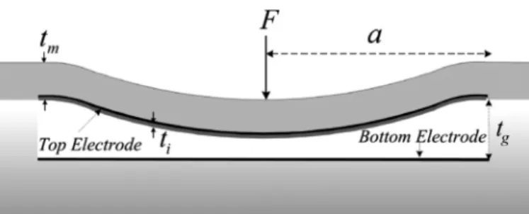
II. Issues in a Transmitting airborne cmUT cell a cross-sectional view of a circular airborne cmUT cell is shown in Fig. 1, where a is the radius of the cmUT,
tg is the gap height, ti is the insulating layer thickness, tm
is the plate thickness, and F is the total force exerted on the plate. an acoustic wave is generated by applying an electrical signal between the electrodes of the cmUT.
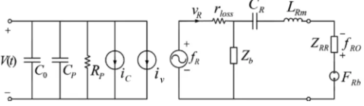
We use the lumped-element equivalent circuit model [18] of the cmUT shown in Fig. 2. The model is for the uncollapsed mode of operation. In this equivalent circuit model, it is assumed that the plate is rigidly clamped and there is no loss of energy to the substrate. The left-hand side models the electrical section, and the right-hand side models the mechanical section.
vr is the spatial rms particle velocity [18] of the plate
and fr is the corresponding transduction force. Frb and fro are the force resulting from static ambient pressure
and the transmitted force generated at the acoustic ter-manuscript received april 15, 2014; accepted July 16, 2014. This work
was supported by the scientific and Technological research council of Turkey (TUbITaK) under project grant 110E216. a. atalar acknowl-edges the support of the Turkish academy of sciences (TUba).
a. Ünlügedik, a. atalar, and H. Köymen are with the department of Electrical and Electronics Engineering, bilkent University, ankara, Turkey (e-mail: [email protected]).
a. s. Taşdelen is with the bilkent University acoustics and Underwa-ter Technologies research cenUnderwa-ter (basTa), bilkent University, ankara, Turkey.
minals, respectively. C0, Crm, and Lrm are the clamped capacitance, the plate compliance, and the mass of the plate, respectively. Zrr is used to model radiation imped-ance in the mechanical section.
The mechanical quality factor, Qm, of a single cmUT cell [19] is Qm r RmL R Xk aRR rk a R k ak a ta X k aR k a RR r r r m m r r = ω +( )( )= ( ) ρρ + ( )( ) 1 0 1 1 ,, (1) where kr is the wave number in air at the resonance fre-quency and ρm/ρ0 is the density ratio of plate material to that of air. The quality factor is proportional to the prod-uct of the thickness-to-radius ratio of the plate, tm/a, and
ρm/ρ0. The density ratio is very high for typical microma-chining materials. This ratio is about 1000 or higher for polymers, 1975 for silicon, and higher for other materials used in micromachining. We used single-crystal silicon1 in
this work.
A. Lumped Nonlinear Compliance of the Silicon Plates
The only means of having a lower quality factor in loss-less cmUTs is to have a very small tm/a ratio. However, atmospheric pressure deflects thinner plates, causing in-creased plate stiffness resulting from nonlinear effects [19], [20]. operation of a cmUT cell can be described using a linear mechanical model if the deflection is small. It is commonly accepted in literature that for center deflection levels up to 20% of plate thickness, the system can be considered elastically linear [21].
nonlinear dependence of the compliance on the deflec-tion of the plate is studied in [19], where an FEa-based method to quantify this dependence is also given. In this study, a/tm is varied between 50 and 200 and the ap-plied uniform pressure is varied between vacuum and 30 saP, where saP = standard atmospheric pressure of 101 325 Pa. a very good approximation to this variation can be expressed as C C X t Xt Xt R Rm P m P m P m ≅ + − + 1 1 0 48. 2 0 014. 3 0 005. 4 (2)
for XP/tm < 12 where XP is the peak plate deflection. Plate compliance Crm is replaced with Cr in the equiva-lent circuit model for airborne applications.
B. Effects of Nonlinearity in Compliance and Force
The nonlinearities in the mechanical section of the air-borne cmUT originate either from the compliance, Cr, or the transduction force, fr. In the mechanical section, we have the following equilibrium relation:
f F Cx L L t x R t x R b R R Rm R R RR R d d d d + = +( + ) 22 + , (3)
where Lr = Xrr(ka)/ω is the equivalent mass resulting from the radiation reactance around the operation fre-quency ω.
If the device is excited with high ac signal levels, the nonlinearity in the force term becomes dominant. The dis-placement dependency of the force term, g′(u), can be expressed as g u u u u mm um m ′ = + + + + ++ = ∞
∑
( ) 13 25 73 2 49 3 2 13 , 4 (4) where u = xp/tge and tge is the effective gap height definedin the appendix.
Using a Taylor series expansion around u = 0, it is clear that the coefficients of higher order terms increase and converge to 0.5 for large orders. These terms are effective even for small normalized displacement levels.
Using (2), the restoring force term in (3) can be writ-ten as
Fig. 1. cross-sectional view of a circular cmUT.
1 The density, ρm = 2370 kg/m3, Poisson ratio, σ = 0.14, and the
young’s modulus, Y0 = 148 GPa are taken for silicon in this work.
TablE I. dimensions of cmUTs Used in the Examples.
cmUT-I cmUT-II
a Plate radius (mm) 1.9 2.05
tm Plate thickness (μm) 80 80
tge Effective gap height (μm) 6.4 6.4
ti Insulating layer thickness (μm) 1 1
Vr collapse voltage in vacuum (v) 646 558
Fb/Fg normalized exerted pressure 0.5 @ saP 0.67 @ saP
Vc collapse voltage for the given normalized pressure (v) 308 172
Expressions for Vr, Vc, Fb/Fg are given in the appendix. saP = standard atmospheric pressure: 101 325 Pa.
X C tC u t t u tt R R ge Rm ge m ge m ≅ + − 5 1 0 48 0 014 2 2 . . 33 3 4 4 0 005 u t t u + ge m . . (5) The nonlinearity resulting from the second-order term in the compliance is studied both as simple spring con-stant behavior [22] and for its effect on the mEms switch and resonators [23]–[25]. It is shown that when the only significant nonlinear term in the dynamic force balance equation is the second term in the compliance, the reso-nance frequency shifts to higher values as the displace-ment amplitude increases. This effect is referred to as the duffing effect [26]. However, as the displacement ampli-tude increases, the nonlinearity in the force also becomes significant. This nonlinearity causes the resonance to shift to lower frequencies, because its effect opposes that of the compliance nonlinearity.
It is possible to study these effects in cmUTs quan-titatively using the equivalent circuit model. The coef-ficient of the second-order nonlinear term in the compli-ance in (2), or the third-order term in the restoring force in (5), is 0.48(tge/tm)2. t
ge/tm is kept usually significantly
smaller than unity in cmUT designs to avoid excessive bias and drive voltages. Therefore, 0.48(tge/tm)2 is much
smaller than the coefficient of the corresponding term in the transduction force in (4). The duffing effect cannot be observed isolated from the nonlinearity in transduction force in cmUT designs where the tge/tm ratio is less than unity.
We studied the effect of nonlinearities for cmUT-I, the design dimensions and critical parameters of which are given in Table I, using an equivalent circuit and a com-mercial harmonic balance simulator (advanced design system, agilent Technologies Inc., santa clara, ca) [27].
cmUTs are usually operated with an ac voltage super-imposed over a dc bias voltage [28]–[31]. The frequency of the ac voltage is in the vicinity of the resonance frequency of the cmUT in this mode for efficient operation.
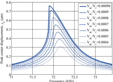
Fig. 3 illustrates the operation of cmUT-I in this mode. We ignored the plate depression resulting from atmospher-ic pressure in these simulations to have comparable results in prior studies [23]–[26]. The model is terminated by the
radiation impedance of the cmUT in air, to avoid indefi-nitely large displacement amplitudes at resonance. The cmUT cell is biased at 0.8Vr, and the sinusoidal signal
amplitude, Vac, is varied up to 0.00096Vr, beyond which
the cmUT collapses. It is clear that the frequency shift caused by the force nonlinearity becomes visible even at very low ac drive levels. The peak center swing amplitude is only 0.76 μm at collapse threshold where the dc depres-sion is 1.175 μm. The only loss mechanism to limit the swing amplitude at the resonance frequency is the radia-tion resistance, which is very low in air. Therefore, collapse occurs at very low swing amplitude in biased operation. The swing increases for a lower bias voltage; however, the swing amplitude remains limited by the nonlinearity at all bias levels. This nonlinear effect has been studied as a limitation in mEms resonators [24], [25].
III. design Procedure for large swing in Unbiased operation
A. Full Swing With Minimum Voltage Amplitude
1) Operation Without Bias Voltage: cmUTs can also
be driven without bias at half of the frequency of opera-tion as
V t( )=Vmcosω2t, (6) where ω is the radial frequency of operation [32], [33].
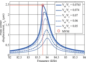
Fig. 4 shows the harmonic balance simulation results of cmUT-I for the unbiased mode when operated under saP. Increasing the drive amplitude lowers the resonance frequency and increases the displacement amplitude. The plate center is already depressed by 3.2 μm at saP, and there is 2.95 μm clearance before the plate center hits the substrate. Part of this clearance is used by further static Fig. 2. Equivalent circuit model for the cmUT. definitions are given
in the appendix. The velocity and force in the mechanical section are spatial rms variables.
Fig. 3. calculated ac peak center displacement as a function of frequency for cmUT-I at different ac levels with a dc bias of 0.8Vr in vacuum.
deflection caused by the applied sinusoidal electric field, and another part by the sinusoidal swing of the plate. at the maximum dynamic swing of 2.46 μm, 83% of the clearance is utilized before the plate collapses.
a large plate swing at low excitation voltage ampli-tude is an important design target for airborne transduc-ers. Unbiased operation provides the option of reaching a swing amplitude which uses almost the entire remaining gap after static depression. We call this swing amplitude the full swing in this work. It is discussed in the follow-ing subsection that if the cmUT is driven at a certain frequency, the full swing without collapse can be obtained using the lowest drive voltage amplitude. We refer to this optimum mode of operation as the minimum voltage mode (mvm) in this paper for better readability. The operating point of mvm for cmUT-I is shown in Fig. 4.
2) Dependence of Swing and Collapse on Drive Ampli-tude and Frequency in Unbiased Operation: We fabricated
cmUT-I and measured the free-field pressure. The details and methodology of fabrication, the measurements and the differences between the fabricated cmUT and the de-sign specifications are discussed in sections Iv and v-b, respectively. The free-field measurements of the emitted acoustic pressure at 71.4 mm distance are given in Fig. 5(a), together with the calculated variation of the dynam-ic component of the center displacement of the plate in Fig. 5(b).
It is important to note that the lowest frequency, 84.1 kHz, falls short compared with the mvm frequency, 84.5 kHz, in achieving maximum pressure at a lower drive level. The simulation results given in Fig. 5(b) predict mvm at 83.7 kHz, where 0.5tge dynamic swing is achieved at 0.09Vr (58 v). a gradually decreasing swing can be obtained at higher frequencies, but at larger drive ampli-tudes.
The pressure increases in agreement with Fig. 5(b) un-til the center of the plate starts tapping the substrate,
where pressure level saturates. The collapse event mani-fests itself as a tapping action in mvm. a precise mea-surement of this phenomenon is difficult, because a large transient swing can interrupt the uncollapsed operation. There is an obvious difference of about 1% error between the designed frequency and realization. Furthermore, the maximum pressure is obtained in mvm at a drive voltage of 0.14Vr, compared with 0.09Vr in the simulation. The
difference is due to the loss mechanisms of cmUTs, which are discussed and modeled in section v. This loss also avoids collapse at the lower frequency of 84.1 kHz, and maximum swing is reached gradually, contrary to what is predicted by the lossless simulation.
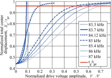
The mvm and its relation with the gap height is better understood when the variation of the total displacement, the sum of static and dynamic components, is examined. The calculated total center displacement normalized to effective gap height, tge, versus normalized drive voltage
amplitude for cmUT-I is plotted in Fig. 6 for various Fig. 4. calculated ac peak center displacement as a function of frequency
for unbiased cmUT-I for various ac drive voltages under standard atmo-spheric pressure, 101 325 Pa.
Fig. 5. (a) measured acoustic pressure for different drive levels at various frequencies near mvm for cmUT-I, (b) calculated normalized dynamic center displacement for different drive levels at various frequencies near mvm for cmUT-I.
frequencies. The maximum swing of the center is limited by the gap height. It is seen that a steady-state operation with full maximum swing, equal to tge, is possible. The
maximum swing is achieved with lowest drive amplitude at 83.7 kHz.
The plate center is already depressed to 0.439tge by
the atmospheric pressure, which can be seen as a start-ing point in Fig. 6. The swstart-ing extends across the entire effective gap as the drive level is increased for frequencies beyond 83.7 kHz. For cmUT-I, the free movement of the plate center is limited to 0.96tge, the gap height, because
of the insulating layer. This limit is also shown in Fig. 6. as the drive voltage is increased, dc displacement also in-creases and tapping starts when the total center displace-ment reaches 0.96tge. The extra dc depression resulting
from the drive voltage is only 0.021tge at mvm.
The mvm is a large signal operation. The model as-sumes that same displacement profile is maintained at all drive levels. The harmonic component of the transduction force at mvm frequency lags the velocity component by approximately 60° in cmUT-I, which is imposed by the mechanical LC section. The quadrature component of the force compensates this phase difference at mvm condi-tions, where the in-phase force component maintains the full swing against radiation resistance.
at a lower frequency, 83.3 kHz, the plate collapses at 0.11Vr, where the dynamic part of the center displacement
reaches to only 0.281tge. The maximum dynamic swing is
less than that of mvm and occurs at higher drive voltage amplitude.
Fig. 6 shows that cmUT does not collapse, even for very high drive levels, at frequencies higher than mvm frequency in unbiased operation if the insulator thickness,
ti, is zero. The swing gradually increases as the drive
am-plitude increases and approaches tge. This phenomenon
can be interpreted physically as follows: beyond mvm frequency, the mass of the plate appears as the main
reac-tance that impedes the motion. The phase compensating quadrature force component is also inductive. The total impeding effect becomes more pronounced as the drive amplitude increases.
B. Resonance Frequency
The plate resonates in air at a frequency in the vicinity of the unstiffened mechanical resonance frequency of the clamped elastically linear plate, when driven in mvm. The mechanical resonance frequency can be obtained from the compliance and mass of the plate in terms of its dimen-sions and material properties. For example, the unstiff-ened resonance frequency of cmUT-I is 83.9 kHz, whereas the mvm frequency is estimated as 83.7 kHz using the equivalent circuit model with stiffened compliance, Cr. Unlike the biased operation, there is no pronounced spring softening effect in this mode. The resonance frequency is only very slightly pulled by the transduction force. The following relation between tm/a and kra can be obtained at
the unstiffened mechanical resonance frequency:
t am =( )k a cr 0
(
−Y)
m. 2 0 9 80 1 σ ρ (7) C. Static Depressionlower quality factors are achieved with thinner plates (higher a/tm ratio), but thinner plates yield more under atmospheric pressure. This necessitates a deeper gap. The available normalized total displacement at the center of the plate is limited to
X t FF pmax g Pb Pg < −1 (8)
for any depression level. The normalized depression level,
FPb/FPg, can be expressed as F FPbPg tt ta P Y m ge m = − 4 0 2 0 3 16 (1 σ ). (9)
The depression depends on a/tm and tm/tge. The de-pression level must be carefully specified at the design stage to 1) avoid unnecessarily high voltage levels and 2) maintain elastically linear operation of the plate.
The maximum displacement of the plate center is lim-ited to gap height, which can be taken as tge, approxi-mately. Therefore, tge/tm < 0.2 can be taken as the range for mechanically linear plate compliance. Using (7) in (9), we have t t k a c Y P F F ge m r m Pb Pg = − <− 1 400 27 1 0 2 4 0 4 2 0 02 1 ( ) ρ ( σ ) . (10) which yields Fig. 6. calculated unbiased cmUT-I normalized total center
displace-ment versus normalized drive voltages. The normalized gap height for tg
( )k ar FFPb . Pg
4 >14 7 (11)
for silicon in air under saP. From (9), we also have
a tm FFPbPgttgemP Y FF / Pb Pg = − 163 1 0 <35 5 0 2 1 4 ( σ ) . 1 4/ . (12)
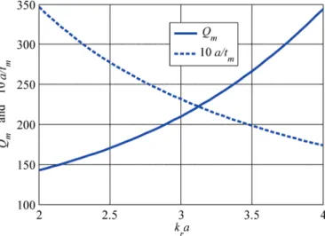
Qm and a/tm are shown as a function of kra as
calcu-lated from (1) and (7) in Fig. 7. Inspection of these graphs indicates that a low quality factor requires a large a/tm ratio at kra values near 2. smaller values of kra cannot be
used because static deflection is too high at those values. This imposes a lower limit for attainable Qm. For example, the minimum kra for linear compliance is 2.0 and 3.5 at FPb/FPg = 0.9 and 0.1, respectively. For these cases, we have a/tm = 34.6 and 20.0, and Qm = 142 and 265.
D. Design of 85 kHz Airborne CMUT
a cmUT cell for biased or unbiased operation can be designed using (1), (7), (8), (10), and (12). From (8), we know that a large FPb/FPg means a high static depres-sion and leaves little room for dynamic movement. The static depression is large for thin plates, which offer larger bandwidth.
one design approach is as follows: 1) choose FPb/FPg.
2) set an allowable value of kra (smaller values give
lower Qm from Fig. 7) using (11) and determine tge/
tm from (10).
3) at the chosen kra value, determine Qm and a/tm from Fig. 7.
4) From the specified operation frequency, find a, tm, and tge.
5) Find the collapse voltage and check whether it is less than the insulator breakdown voltage. If not, iterate again.
as an example, we design a cmUT cell at 85 kHz. We set a medium level of static depression by choosing FPb/FPg
= 0.5. We choose kra = 2.3 for tge/tm = 0.2 using (10). Fig. 7 gives a/tm = 29 and Qm = 160. Hence, we find a = 1.46 mm, tm = 50 μm, and tge = 10 μm. From (28), we find Vr = 1055 v and from (25), we find collapse voltage,
Vc, as 503 v. because this value is comparable to the di-electric breakdown voltage of our insulation layer, we start again with a larger value of kra. Using (10), we choose kra ≈ 3 and tge/tm = 0.08. Fig. 7 gives a/tm = 23.8 and
Qm = 210. Hence, we find a = 1.9 mm, tm = 80 μm, and
tge = 6.4 μm. For this case, Vr = 646 v and Vc = 308 v. This design is cmUT-I, the simulation and measurement results of which have already been discussed.
To increase the output power, we can consider increas-ing tge to the linear elastic limit, 16 μm, in cmUT-I for mvm operation. When only the gap is increased, the
stat-ic displacement remains the same and FPb/FPg becomes
lower. Therefore, larger swing can be obtained at the ex-pense of larger drive voltage. The maximum displacement is reached in all tge values at the same normalized drive
level of Vm/Vc ≈ 0.17. This corresponds to 13.2, 7.2, 3.6,
and 1.2 μm maximum swing at 353, 151, 59, and 38 v drive amplitude for 16, 10, 6.4, and 4 μm effective gap heights, respectively. The output field pressure is 11.3 db greater compared with cmUT-I when the gap is 16 μm.
another approach is to start by specifying the frequen-cy and power delivered to the medium at the transducer surface. The required maximum dynamic displacement amplitude, xpmax, can then be determined. It can be seen
from Fig. 6 that a rather small extra static displacement occurs because of the applied voltage drive in the normal range of operation of mvm. The normalized depression can be determined using required total displacement and (8). The radius can now be determined from (10). Hav-ing kra specified, a/tm, and hence tm, can be found for a
minimum Qm. because the normalized depression is also
specified, tge is found from (9).
The precision of the fabrication processes is very impor-tant in realizing the designs to meet the specifications. To compensate for the fabrication tolerances, we fabricated eleven cmUT cells with radii ranging from 1.7 to 2.2 mm and with a fixed effective gap of 6.4 μm.
Iv. Fabrication
an 80-μm-thick, highly doped, double-side polished silicon wafer2 is used as the plate and a 3.2-mm-thick
bo-rosilicate wafer is used as the substrate of the cmUT. a 1-μm-thick layer of silicon oxide is grown by wet thermal oxidation process on the silicon wafer in a diffusion fur-Fig. 7. calculated Qm and a/tm versus kra for an airborne cmUT.
2 The thickness tolerance of the silicon wafer at the center is ±8 μm
nace to form an insulation layer. For the electrical contact, the silicon oxide on one side is removed.
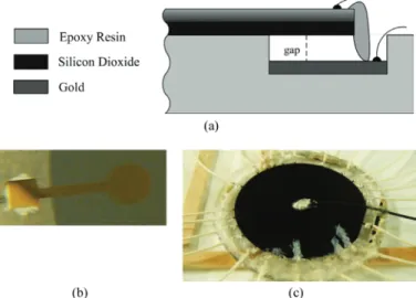
cavities having a gap height of 6.4 μm are chemically etched on the borosilicate wafer, using buffered oxide etch-er (boE 7:1), as seen in Fig. 8(a). Each gap is extended to the rim of the substrate by a 1-mm-wide channel of same depth, to form a bed for electrical connection. 40-nm-thick titanium and 100-nm-thick gold layers are thermally evap-orated on the bottom surfaces of the gaps to act as the bottom electrode, and on the bottom of the channels for electrical connection. To finalize the fabrication process, the wafer is anodically bonded.3
The wafer is placed in a vacuum chamber to seal the channel by using a low-viscosity epoxy resin (biresin cr80 epoxy resin and cH80-2 hardener, sika, baar, switzer-land). This way, the gas in the gap is sucked out through the epoxy. The wafer is left in the vacuum chamber at room temperature for 12 hours until the epoxy hardens. The wafer is then put in an oven at 70°c for 3 hours for curing.
We used an epoxy resin degassing desiccator and its vacuum pump as the vacuum chamber in our fabrication. The minimum pressure that can be obtained in this vac-uum system is 0.12 saP. This finite pressure in the gap causes some deviation from the design parameters given in Table I. However, it also offers the possibility of testing our model-based design and characterization approach which can handle this deviation once the pressure in the gap is known. because cmUTs are operated at atmospheric pressure, the pressure difference causes a static deflection on the plate. This deflection is taken into account in the
FPb/FPg parameter in the model. The pressure in the gap
is expected to increase because the gap volume is reduced by this deflection. We calculated that this pressure
in-crease yields insignificant difference in FPb/FPg for both cmUTs, because of the additional volume of the channel. The effective pressure on the plate is 0.88 saP and FPb is calculated using this pressure difference.
The electrode channel also has the structure of a long rectangular cmUT with a width of 1 mm and a gap of 6.3 μm. We placed silicone rubber so as to cover the chan-nel area on the plate surface to damp out any parasitic vibration, as can be seen in Fig. 8(c).
v. results
A. Characterization Using the Equivalent Circuit Model
We characterized the fabricated cmUT-II by measur-ing its electrical input impedance with an impedance/ gain-phase analyzer (HP 4194a). The measurement is performed in long averaging mode with a bias voltage of 40 v. The equivalent circuit model is used to obtain the conductance of cmUT-II. The variation of conductance versus frequency is depicted in Fig. 9 for both the mea-surement and the model. The model predicts a 2.2% lower resonance frequency, about twice as much peak conduc-tance, no baseline conducconduc-tance, and about half as much bandwidth. The predicted quality factor is 190, whereas the measured value is 120. The discrepancies in these pa-rameters may have to do with the validity of the assump-tions about the material properties, residual stress in the plate, the dielectric loss in the insulating oxide layer, or some of the dimensions such as gap height and plate thick-ness.
We compensated for the discrepancies by making a few corrections in the model:
1) Resonance Frequency: mechanical resonance
frequen-cy depends on LrmCrm and to the spring softening result-ing from bias. LrmCrm yields (7), which shows that the frequency depends on the square of radius, thickness, and the mechanical material constants. material constants we used in this work for single crystal silicon are the most widely used values in literature. These constants are rep-resentative and can have a significant variation between different wafer samples. Hence, we need not consider the effect of residual stress separately, both because it modi-fies the young’s modulus additively and because it is usu-ally few orders of magnitude low. It is not necessary to have the accurate knowledge of each of these variables to match the model to the frequency of resonance. The frequency is most sensitive to the radius, but we measure the radius quite accurately. Tuning the thickness to have (7) hold with the measured resonance frequency is most appropriate. The spring softening is affected by the gap height. The gap height also affects the peak conductance level. The spring softening effect can be ignored for initial frequency correction because the bias voltage is very low, and its effect can be checked after the entire tuning pro-cess is completed. The plate thickness is nominally 80 μm. Fig. 8. (a) cross-sectional view of a fabricated single cell after anodic
bonding, lead wire connections, and epoxy, (b) top (glass) view of a section with electrode (Ti-au) of the fabricated cmUT, (c) bottom (sili-con) view of the fabricated cmUT.
To match the resonance frequency of the model and the measurement, we set the plate thickness to 81.63 μm.
2) Conductance Baseline: In Fig. 9, the baseline in the
conductance measurement is due to the dielectric loss of the insulating layer. The dielectric loss of the oxide layers which we can produce in our laboratory is usually rath-er high. The effective loss tangent is calculated from the measurements as 0.0077. The total effective capacitance, (C0 + Cp), is obtained from the slope of the measured sus-ceptance as 60.4 pF. C0 is calculated from (20) as 17.7 pF, leaving a parasitic capacitance of Cp = 42.7 pF. The par-allel effective dielectric loss resistance can be written as
RP C C p
= +1
0
ω( )tan .δ (13)
Cp and RP are connected in parallel with C0 in the elec-trical side of the equivalent circuit model, as depicted in Fig. 10.
3) Losses and Bandwidth: a certain amount of vibration
energy is lost to the substrate. because the plate motion is counterbalanced by the substrate, the loss can be modeled by appropriate parallel impedance, Zb, as shown in Fig. 10. We analyzed the way Zb affects the equivalent circuit by modeling the propagation into the substrate from the bottom surface of the gap. It is possible to show that Zb is a very large effective mass, which cannot have any signifi-cant effect on the performance.
There are two other possible mechanisms of loss. The first one is due to the in-plane components of the vibra-tion induced in the plate. When the plate vibrates, a cer-tain amount of in-plane energy is coupled to the silicon wafer at its clamped edge. The other is due to the heat generated when air in the gap (0.12 saP) is compressed by the plate in every cycle. The components that model both of these loss mechanisms must appear as series resis-tances connected immediately after the transduction force in the equivalent circuit.
With Zb = ∞, we calculate the combined equivalent loss resistance, using (1):
Q Q R r R simulated measured RR loss RR = + . (14)
The bandwidth that is found from the equivalent circuit model is 387 Hz, whereas we measured it as 615 Hz. The loss resistance, rloss, is found from (14) as 0.68Sρ0c0.
4) Peak Value of Conductance: adjustment at the
con-ductance peak is made by changing the effective gap height to 6.605 μm, which does not result in a significant shift in the resonance frequency; hence, any further modification in thickness, tm, is rendered unnecessary. It must be noted that this value of plate thickness is not necessarily the ac-tual thickness, but its combination with assumed material properties and cmUT dimensions provide accurate pre-dictions of the fabricated cmUT performance parameters. The operational parameters of cmUT-II, Fb/Fg, Vr, and Vc, are changed to 0.54 @ 0.88 saP, 602 v, and 264 v, respectively, after these modifications.
We performed the same characterization on cmUT-I and we obtained 80.3 μm and 6.7 μm for plate thickness and effective gap height, respectively. We calculated the series loss as 0.86Sρ0c0. When we used these values in the modified equivalent circuit, we observed that mvm oc-curs approximately at 84.2 kHz with drive amplitude of 90 v, which is 0.14Vm/Vr, compared with 0.09Vm/Vr in the lossless model. This value is in exact agreement with the measurements in Fig. 5(a).
B. Pressure Levels
a set of far-field measurements is made with cmUT-II. The field pressure is measured by using a calibrated microphone (pressure-field microphone, b&K 4138, bruel and Kjaer, nærum, denmark) placed at 90° to the field [34], mounted on a preamplifier (b&K 2633, bruel and Kjaer) using an adaptor (b&K Ua 160, bruel and Kjaer). The microphone is polarized by a power supply (b&K 2807, bruel and Kjaer). a spectrum analyzer (HP8590l, Hewlett-Packard, Palo alto, ca) is used to measure the preamplifier output voltage. The measurements are per-formed using continuous wave excitation in the laboratory environment where the setup is placed at least 1.5 m away from any reflecting surface and 2 m away from the ceiling. The measurements are made above 70 kHz, where attenu-ation in air is more than 2.2 db/m [35]. because the sound Fig. 9. conductance of the cmUT as measured and as calculated from
the values found in fabrication.
waves cannot persist with this level of attenuation, we did not observe any effects of reflected waves.
The microphone capacitance is given as 3.2 pF. We calibrated the measurement setup, from the adaptor to the spectrum analyzer, using a 3.3-pF capacitor and a balanced 1 mvrms voltage source.
Input signal amplitude is increased up to about 300 v peak or when collapse occurs. The measurements were made in a laboratory where the ambient temperature and relative humidity were 18°c and 52%, respectively. The ambient pressure was monitored and found to remain in the vicinity of saP on all days when the measurements were made. The density of air, ρ, and velocity of sound,
c, are taken as 1.2 kg/m3 and 340 m/s, respectively.
at-tenuation in air in these ambient conditions and at the measurement frequencies is interpolated from the data given in [35].
The microphone is used to measure the acoustic pres-sure generated by the cmUT at a distance of 250 mm, for different normalized ac voltage values. To compare these results with the modified circuit model, we simulated the source sound pressure levels measured at 250 mm by using the equation given in [36]:
p r( , , )θ ϕ jρckSD U( ) erjkr,
π θ
= 2 A − (15)
where k is the wave number; r is the measurement range, 250 mm; D(θ) = 1, because the pressure is measured on the axis; Ua is the average velocity of the plate; and S is surface area.
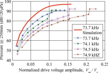
Fig. 11 shows measurement results of fabricated cmUT-II output pressure levels at different frequencies together with the equivalent circuit simulator prediction for 73.7 kHz, the mvm for this cmUT. There is a differ-ence of about 6 db between the model prediction and the measurements at all drive levels. There are similar differ-ences of 2 to 6 db at other frequencies as well.
The cmUT can generate approximately 0.66 Pa (90.4 db//20 μPa) at 250 mm in mvm when driven by 71 v amplitude. The model predicts that full swing occurs at 96 v at this frequency. However, tapping can commence prematurely at a lower drive level than predicted because the plate center can hit the substrate during the transient overshoot. This is observed in other frequencies, particu-larly at 74.1 kHz, where collapse occurred at a drive level lower than that of mvm. The effect of attenuation in air on the measured values at mvm is 0.55 db [35].
The pressure at the cmUT surface can be estimated as 138.5 db//20 μPa. The source level (sl) is calculated as 78.9 db//20 μPa@1m, if attenuation is ignored. There-fore, one can obtain 118.9 db sl if 100 similar cells are used in a closed packed cluster.
In the simulator, we used (15) to calculate the source sound pressure level under the rigid baffle assumption. another way to estimate the radiated pressure is to cal-culate the real power delivered to air at the acoustic port using radiation resistance and particle velocity, and
as-suming that this power is radiated omnidirectionally to the hemisphere. radiated pressure levels thus obtained are 2.4 db lower than the predictions of (15).
We tested twelve functioning cmUT cells in two steps: 1) impedance measurement and analysis and 2) field pres-sure meapres-surements. In eight of the cells, we have a similar difference of 4 to 6 db between the estimated and mea-sured pressure levels at mvm. In four of the cells, the dif-ference is larger, but still less than 9 db in the worst case. We investigated the mismatch between the predicted and measured field pressures
1) Instead of considering only the variation of tm and
tge, we examined the variation of the radius, a, and the material properties of silicon in the characteriza-tion. The pressure generated at mvm is not sig-nificantly affected by widely differing combinations which yield the same impedance and the same mvm frequency.
2) We considered the validity of the rigid baffle assump-tion in the model and the presence of other cells in the wafer, both experimentally and theoretically. We concluded that the rigid baffle assumption is appro-priate.
3) There is a change in the displacement profile [37] when the cell is driven at high voltage levels, because the separation between the center and the bottom electrode becomes very small. The motion becomes more concentrated at the center and the beamwidth becomes greater. We did not consider this change in the profile. The field pressure may be one or two decibels lower when the change in profile occurs. This may account for the increased discrepancy at high voltage drive levels near collapse.
We concluded that the differences between the mea-sured and predicted pressure levels are due to an accu-Fig. 11. The pressure measurements of cmUT-II at various frequen-cies and driving voltages. simulation predictions are given for mvm at 73.7 kHz only. The plate in cmUT-II hit the substrate at normalized voltage amplitude of 0.12 @ 73.7 kHz; 0.11 @ 74.1 kHz; 0.16 @ 74.5 kHz; and 0.21 @ 74.9 kHz in the measurements.
mulation of the tolerances and minor inaccuracies of the measurement equipment and the setup. The free-field ab-solute pressure measurements are troublesome, particu-larly at high frequencies. These measurements are based on various assumptions and corrections [34]. a tolerance of a few decibels is always in order.
vI. conclusion
We presented a method to obtain high pressure levels in airborne applications without any dc bias and using relatively low voltage amplitudes. We identified mvm, at which a cmUT produces maximum pressure using the lowest possible drive amplitude at a specific frequency. We presented a methodology for the design of airborne cmUT cells with maximum lossless bandwidth, which employs static atmospheric depression as a design parameter. We demonstrated how fabricated cmUT cells can be very ac-curately characterized using the equivalent circuit model. We experimentally obtained 90.4 db//20 μ[email protected] m pressure level at 73.7 kHz with cmUT-II using 71 v driv-ing voltage amplitude, which corresponds to 78.9 db sl. We showed that we can predict the performance very ac-curately during the design stage. Higher pressure levels can be obtained at the same frequency from a single cell of the same area if a larger gap is employed with the same plate. For example, if the gap is increased from 6.4 μm to 16 μm in cmUT-II, the predicted pressure level is in-creased by 11.3 db, whereas the measured pressure level is expected to increase by more than 11.3 db.
driving cmUTs at mvm can be done similarly to piezoelectric transducers, because the operation does not require any dc bias. at most, a simple low-power trans-former may be necessary whatever the voltage amplitude may be, because the mvm is very efficient.
appendix
In Fig. 2, vr, the spatial rms particle velocity of the plate, is found as
v tR( )= dx tdRt( ) (16) and
x tR( )=x tP( )5 , (17)
where xP is the displacement at the center of the plate.
The corresponding force term in the model is [18]:
f tR C V tt g x tt ge P ge ( )= ( ) ( ) ′ 5 20 2 (18) where tge =tg+ti/ε ,r (19) C0 =ε π0t a2 ge (20) and g u u u u u ′( )= 211−1 −tanh( ). (21) mass and compliance for the rms variables in the me-chanical section are
LRm = πa t2 m mρ (22) and C a Y t Rm m = 95 1− 16 2 2 0 3 ( σ ) , π (23)
where ρm is the density of plate material, σ is the Poisson ratio, and Y0 is the young’s modulus.
In Fig. 2, external static force is denoted by Frb and is given as
FRb= 35 a P2 0
π , (24)
where P0 is the external ambient static pressure.
The collapse voltage, Vc, under ambient static pressure is given as V Vcr FF FF Pb Pg Pb Pg ≈ − + − + 0 9961 1 0468 0 06972 0 25 0 2 . . . . .001148 FFPb 6 Pg , (25) where FPg Ctge Rm = 5 (26) and FPb= 13 a P2 0 π (27)
and Vr is the collapse voltage in vacuum, given as
V t a t t Y r =8 m2 ge3 2 1 2/ m/ 27 10− 0 2 ε( σ ). (28)
The center displacement, XPc, at the collapse voltage is given as
X tgePc FF FF Pb Pg Pb Pg ≈ + − − + 0 4648. 0 5433. 0 01256. 0 35. 2 00 002775. FFPb 9. Pg (29) The radiation impedance in the mechanical section is
ZRR( )ka =RRR( )ka +XRR( ),ka (30) where Xrr(ka) = πa2ρ
0c0X1(ka) is the radiation reactance
and Rrr(ka) = πa2ρ
0c0R1(ka) is the radiation resistance
in air, where X1(ka) and R1(ka) are given in [27] for a clamped plate.
acknowledgments
The authors acknowledge the support given by Prof. m. Çalışkan and a. bodur in the department of mechani-cal Engineering, mETU, ankara. Prof. Çalışkan made his acoustics lab available for the initial measurements, and mr. bodur helped with those measurements throughout the process. Their support has been greatly appreciated.
references
[1] s. adler, P. Johnson, and o. Wygant, “low frequency cmUT with vent holes,” U.s. Patent 8 455 963 b1, Jun. 4, 2013.
[2] W. m. d. Wright and s. G. mcsweeney, “a tethered front-plate electrode cmUT for broadband air-coupled ultrasound,” in Proc.
IEEE Ultrasonics Symp., 2013, pp. 1716–1719.
[3] J. s. mcIntosh, d. a. Hutchins, d. r. billson, T. J. robertson, r. a. noble, and a. d. r. Jones, “The characterization of capacitive micromachined ultrasonic transducers in air,” Ultrasonics, vol. 40, no. 1, pp. 477–483, may 2002.
[4] d. a. Hutchins, d. W. schindel, a. G. bashford, and W. m. d. Wright, “advances in ultrasonic electrostatic transduction,”
Ultra-sonics, vol. 36, no. 1, pp. 1–6, 1998.
[5] l. chuan, d. a. Hutchins, and r. J. Green, “response of an ultra-sonic communication channel in air,” IET Commun., vol. 6, no. 3, pp. 335–343, Feb. 2012.
[6] I. o. Wygant, m. Kupnik, J. c. Windsor, W. m. Wright, m. s. Wochner, G. G. yaralioglu, m. F. Hamilton, and b. T. Khuri-yakub, “50 kHz capacitive micromachined ultrasonic transducers for generation of highly directional sound with parametric arrays,”
IEEE Trans. Ultrason. Ferroelectr. Freq. Control, vol. 56, no. 1, pp.
193–203, Jan. 2009.
[7] c. canali, G. d. cicco, b. morten, m. Prudenziati, and a. Taroni, “a temperature compensated ultrasonic sensor operating in air for distance and proximity measurements,” IEEE Trans. Ind. Electron., vol. 29, no. 4, pp. 336–341, nov. 1982.
[8] r. Hickling and s. P. marin, “The use of ultrasonics for gauging and proximity sensing in air,” J. Acoust. Soc. Am., vol. 79, no. 4, pp. 1151–1160, apr. 1986.
[9] l. mauritzson, J. Ilver, G. benoni, K. lindström, and s. Willner, “Two-dimensional airborne ultrasound real-time linear array scan-ner—applied to screening for scoliosis,” Ultrasound Med. Biol., vol. 17, no. 5, pp. 519–528, 1991.
[10] T. Tsujimura, T. morimitsu, and T. yabuta, “shape-reconstruction system for three-dimensional objects using an ultrasonic distance sensor mounted on a manipulator,” J. Dyn. Syst. Meas. Control, vol. 111, no. 2, pp. 180–186, Jun. 1989.
[11] K. K. Park and b. T. Khuri-yakub, “3-d airborne ultrasound syn-thetic aperture imaging based on capacitive micromachined ultra-sonic transducers,” Ultraultra-sonics, vol. 53, no. 7, pp. 1355–1362, apr. 2013.
[12] K. suzuki, K. Huguchi, and H. Tanigawa, “a silicon electrostatic ul-trasonic transducer,” IEEE Trans. Ultrason. Ferroelectr. Freq.
Con-trol, vol. 36, no. 6, pp. 620–627, nov. 1989.
[13] m. J. anderson, J. a. Hill, c. m. Fortunko, n. s. dogan, and r. d. moore, “broadband electrostatic transducers; modeling and experi-ments,” J. Acoust. Soc. Am., vol. 97, no. 1, pp. 262–272, Jan. 1995. [14] H. carr and c. Wykes, “diagnostic measurements in capacitive
transducers,” Ultrasonics, vol. 31, no. 1, pp. 13–20, 1993.
[15] m. oksanen, J. varis, J. Hietanen, and J. Wu, “quantitative theory for v-groove capacitive transmitting transducers,” Ultrasonics, vol. 35, no. 3, pp. 205–211, may 1997.
[16] m. I. Haller and b. T. Khuri-yakub, “a surface micromachined electrostatic ultrasonic air transducer,” IEEE Trans. Ultrason.
Fer-roelectr. Freq. Control, vol. 43, no. 1, pp. 1–6, Jan. 1996.
[17] m. Kupnik, m. Ho, and b. T. Khuri-yakub, “cmUTs for air cou-pled ultrasound with improved bandwidth,” in Proc. IEEE
Ultrason-ics Symp., 2011, pp. 592–595.
[18] H. Köymen, a. atalar, E. aydoğdu, c. Kocabaş, H. K. oğuz, s. olçum, a. Özgürlük, and a. Ünlügedik, “an improved lumped el-ement nonlinear circuit model for a circular cmUT cell,” IEEE
Trans. Ultrason. Ferroelectr. Freq. Control, vol. 59, no. 8, pp. 1791–
1799, aug. 2012.
[19] a. Unlugedik, a. atalar, and H. Koymen, “designing an efficient wide bandwidth single cell cmUT for airborne applications using nonlinear effects,” in Proc. IEEE Ultrasonics Symp., 2013, pp. 1416– 1419.
[20] m. Kupnik, I. o. Wygant, and b. T. Khuri-yakub, “Finite element analysis of stress stiffening effects in cmUTs,” in Proc. IEEE
Ultra-sonics Symp., 2008, pp. 487–490.
[21] E. ventsel and T. Krauthammer, Thin Plates and Shells, 1st ed., new york, ny: marcel dekker, 2001.
[22] l. d. landau and E. m. lifshiftz, Mechanics, 3rd ed., oxford, UK: butterworth-Heinemann, 1999.
[23] a. a. batista, F. a. oliveira, and H. n. nazareno, “duffing oscilla-tors: control and memory effect,” Phys. Rev. E, vol. 77, no. 6, art. no. 066216, Jun. 2008.
[24] v. Kaajakari, T. mattila, a. oja, and H. seppa, “nonlinear limits for single-crystal silicon microresonators,” IEEE J.
Microelectro-mech. Syst., vol. 13, no. 5, pp. 715–724, oct. 2004.
[25] v. Kaajakari, (2014, mar.). mEms tutorial: nonlinearity in micro-mechanical resonators. [online]. available: http://www.kaajakari. net/~ville/ research/tutorials/nonlinear_resonators_tutorial.pdf [26] P. J. Holmes and d. a. rand, “The bifurcations of duffing’s
equa-tion: an application of catastrophe theory,” J. Sound Vibrat., vol. 44, pp. 237–253, Jan. 1976.
[27] H. K. oguz, s. olcum, m. n. senlik, v. Tas, a. atalar, and H. Koy-men, “nonlinear modeling of an immersed transmitting capacitive micromachined ultrasonic transducer for harmonic balance analy-sis,” IEEE Trans. Ultrason. Ferroelectr. Freq. Control, vol. 57, no. 2, pp. 438–447, Feb. 2010.
[28] s. machida, s. migitaka, H. Tanaka, K. Hashiba, H. Enomoto, y. Tadaki, and T. Kobayashi, “analysis of the charging problem in capacitive micro-machined ultrasonic transducers,” in Proc. IEEE
Ultrasonics Symp., 2008, pp. 383–385.
[29] K. midtbo and a. ronnekleiv, “analysis of charge effects in high frequency cmUTs,” in Proc. IEEE Ultrasonics Symp., 2008, pp. 379–382.
[30] s. olcum, F. y. yamaner, a. bozkurt, H. Koymen, and a. atalar, “deep collapse operation of capacitive micromachined ultrasonic transducers,” IEEE Trans. Ultrason. Ferroelectr. Freq. Control, vol. 58, no. 11, pp. 2475–2483, nov. 2011.
[31] P. Zhang, G. Fitzpatrick, W. moussa, and r. J. Zemp, “cmUTs with improved electrical safety & minimal dielectric surface charg-ing” in Proc. IEEE Ultrasonics Symp, 2010, pp. 1881–1885. [32] F. y. yamaner, s. olcum, H. K. oguz, a. bozkurt, H. Köymen, and
a. atalar, “High-power cmUTs: design and experimental verifica-tion,” IEEE Trans. Ultrason. Ferroelectr. Freq. Control, vol. 59, no. 6, pp. 1276–1284, Jun. 2012.
[33] J. Zahorian, m. Hochman, s. satir, and F. l. degertekin, “bias optimization of dual ring cmUT arrays for forward looking IvUs applications,” in Proc. IEEE Ultrasonics Symp, 2010, pp. 447–450.
[34] Condenser Microphones and Microphone Preamplifiers for Acoustic
Measurement, Data Handbook. bruel and Kjaer, nærum, denmark,
1982.
[35] G. W. c. Kaye and T. H. laby, (2014, mar.). Tables of Physical and
Chemical Constants and Some Mathematical Functions. (16th ed.)
[online]. available: http://www.kayelaby.npl.co.uk/
[36] H. K. oğuz, a. atalar, and H. Köymen, “Equivalent circuit-based analysis of cmUT cell dynamics in arrays,” IEEE Trans. Ultrason.
Ferroelectr. Freq. Control, vol. 60, no. 5, pp. 1016–1024, may 2013.
[37] E. aydogdu, a. ozgurluk, a. atalar, and H. Koymen, “lumped ele-ment model of single cmUT in collapsed mode,” IEEE Ultrasonics
Symp., 2013, pp. 283–286.
Aslı Ünlügedik received the b.sc. degree in
elec-trical and electronics engineering in 2004 from yeditepe University, Istanbul, Turkey, and the m.sc. degree in electronics and communication engineering from Istanbul Technical University (ITU), Istanbul, Turkey, in 2007. since 2008, she has been pursuing her Ph.d. degree in the depart-ment of Electrical and Electronics Engineering at bilkent University, where she is a research assis-tant. Her current research interests include the design, characterization, and fabrication of cmUTs.
A. Sinan Taşdelen received his b.sc. and m.sc.
degrees from bilkent University, ankara, Turkey, in 2004 and 2007, respectively, both in electrical and electronics engineering. In 2008, he joined the bilkent University acoustics and Underwater Technologies research center (basTa), where he is currently working as head research engineer. His research interests include passive radar, underwa-ter acoustics, transducer design, and biomedical ultrasound.
Abdullah Atalar received his b.s. degree from
the middle East Technical University (mETU), ankara, Turkey, in 1974, and m.s. and Ph.d. de-grees from stanford University, stanford, ca, in 1976 and 1978, respectively, all in electrical engi-neering. He worked for Hewlett–Packard labs, Palo alto, ca, in 1979. From 1980 to 1986, he was on the faculty of mETU as an assistant professor. In 1986, he joined bilkent University as chairman of the department of Electrical and Electronics Engineering and participated in the founding of the department, where he is currently a professor. In 1995, he was a visiting professor at stanford University. From 1996 to 2010, he was the provost of bilkent University. He is currently the rector of that univer-sity. His current research interests include micromachined devices and microwave electronics.
He was awarded the TUbITaK science award in 1994. He is an IEEE Fellow and a member of the Turkish academy of sciences.
Hayrettin Köymen received the b.sc. and m.
sc. degrees from the middle East Technical Uni-versity (mETU), ankara, Turkey, in 1973 and 1976, respectively, and the Ph.d. degree from bir-mingham University, UK, in 1979, all in electrical engineering. He worked as a faculty member in the department of marine sciences (mersin) and the department of Electrical Engineering (ankara) at mETU from 1979 to 1990. In 1990, he joined the faculty of bilkent University, where he is a profes-sor in the department of Electrical and Electron-ics Engineering. His research activities have included underwater and airborne acoustic and ultrasonic transducer design, underwater acous-tics, underwater and airborne acoustic systems, acoustic microscopy, ul-trasonic ndT, biomedical instrumentation, mobile communications, and spectrum management.