INVESTIGATION AND CONTROL OF THE STATIC
ELECTRIFICATION IN POLYPROPYLENE
A THESIS SUBMITTED TO
THE GRADUATE SCHOOL OF ENGINEERING AND SCIENCE OF BILKENT UNIVERSITY
IN PARTIAL FULFILLMENT OF THE REQUIREMENTS FOR THE DEGREE OF
MASTER OF SCIENCE IN
MATERIALS SCIENCE AND NANOTECHNOLOGY
By Zelal Yavuz August 2016
ii
INVESTIGATION AND CONTROL OF THE STATIC ELECTRIFICATION IN POLYPROPYLENE
By Zelal Yavuz August 2016
We certify that we have read this thesis and that in our opinion it is fully adequate, in scope and in quality, as a thesis for the degree of Master of Science.
_______________________ H. Tarık Baytekin (Advisor)
_______________________ Tamer Uyar
_______________________ Gülay Ertaş
Approved for the Graduate School of Engineering and Science:
_______________________ Levent Onural
iii
ABSTRACT
INVESTIGATION AND CONTROL OF THE STATIC
ELECTRIFICATION IN POLYPROPYLENE
Zelal Yavuz
M.Sc. in Materials Science and Nanotechnology Advisor: Hasan Tarık Baytekin
August 2016
The electrostatic charging of polymers due to friction is such a common phenomenon in daily usage of polymers that can be a problematic issue for various applications, such as in electronic devices, textile, space industry and so on. Hence, understanding and controlling of the mechanism behind the static electrification, which is basically because of the charge accumulation on the material, is an important subject in terms of the applications.
In the way to understand static electrification of bulk materials, examining the physical and morphological properties is crucial. On the other hand, when the physical properties are considered, the structure of polymer plays a significant role, yet there is a lack of knowledge in the literature about the relation between these structural properties and triboelectricity. As a reason of this, it can be pointed out that in the proposed mechanisms about the frictional electrification the structure-property relation could not get sufficient attention so far. In this thesis, the crystalline structure of polymer, which plays a crucial role in the determination of physical properties of polymeric materials, was studied and by using different treatment techniques, such as microwave radiation and mechanical stress, and the relation between the degree of
iv
crystallinity and triboelectric charging was investigated. Due to its economical cost and heat-sensitive degree of crystallinity that can be changed in a significant way polypropylene (PP) which is a semi-crystalline polymer was used in this study. Hence, by utilizing different spectroscopic and microscopic techniques the relation between physical properties and triboelectrification of polypropylene was investigated in detail. In order to understand the physical and chemical changes taking place in untreated and treated polypropylene X-ray Photoelectron Spectroscopy (XPS), Raman Spectroscopy, X-ray Diffraction (XRD), Atomic Force Microscopy (AFM), Differential Scanning Calorimetry (DSC) are the techniques that were employed.
In this study, by considering the mechanism behind static electrification the potential link between electrification and degree of crystallinity was designated. Furthermore, the generation of charge on the surface of mechanically treated polypropylene film was observed for the first time by this current work. The results lead to the fact that it is possible to convert mechanical energy into electrical energy without any contact between the objects by introducing physical forces onto the insulating materials and the reasons behind non-contact electrification was investigated. Therefore, in the light of the results obtained from this study, more efficient triboelectric generators can be designed to harvest electrical energy from mechanical energy.
Keywords: physical properties, crystallinity, polypropylene, static electrification,
v
ÖZET
POLİPROPİLENDE STATİK ELEKTRİKLENMENİN İNCELENMESİ VE KONTROL ALTINA ALINMASI
Zelal Yavuz
Malzeme Bilimi ve Nanoteknoloji Programı, Yüksek Lisans Tez Danışmanı: Hasan Tarık Baytekin
Ağustos 2016
Polimerlerin gündelik hayatta dokunma ve sürtünme sonucu elektriksel yük ile yüklenmeleri sonucu açığa çıkan statik elektriklenme olayı oldukça sık karşılaşılan bir durum olmakla birlikte, bu durum polimerlerin kullanıldığı birçok alanda, örneğin elektronik cihazlarda, tekstil sanayisinde ve uzay endüstrisinde sorun yaratabilmektedir. Bu sebeple, ani elektriksel yük birikmesi ve yük boşalması sonucu ortaya çıkan statik elektriklenmenin mekanizmasını anlamak ve kontrol altına alabilmek uygulamalar açısından son derece önemli bir konudur.
Yalıtkan ve büyük ölçekli malzemelerin statik elektriklenmesini anlamaya çalışırken, fiziksel ve morfolojik özellikleri incelemek kritik bir rol oynamaktadır. Öte yandan, fiziksel özellikleri ele alındığında polimerlerin yapısının önem arz ettiği görülmekte olup bu yapısal özellikler ile triboelektriklenme arasındaki ilişki hakkında literatürde çok sınırlı miktarda bilgi yer almaktadır. Bunun nedeni olarak sürtünme elektriklenmesinin aydınlatılması konusunda şu ana kadar önerilen mekanizmaların yapı-özellik ilişkisini genellikle göz ardı etmiş olması gösterilebilir. Bu tez çalışmasında, polimerlerin fiziksel özellikleri ele alındığında önemli bir faktör olan kristallenme üzerinde çalışılarak, farklı muamele teknikleriyle (örneğin, mikrodalga
vi
ışıması, mekanik gerilme) değiştirilen kristallik derecesi ile triboelektrik yüklenme (yada yük oluşumu) arasındaki ilişki çalışılmıştır. Yarıkristal özelliğe sahip olan polipropilen (PP) hem ekonomik değerinden dolayı hem de kristallenme derecesinin ısısal işlem sayesinde oldukça farklı değerler alabilmesi nedeni ile seçilmiş ve bu tezde farklı spektroskopik ve mikroskopik teknikler kullanılarak PP in fiziksel özellikleri ve triboelektriklenme özellikleri arasındaki ilişki detaylı bir şekilde ortaya konulmaya çalışılmıştır. Muamele edilmiş ve edilmemiş polipropilende meydana gelen fiziksel ve kimyasal özelliklerindeki değişimleri anlayabilmek için X-ışınlı Fotoelektron Spektroskopisi (XPS), Raman Spektroskopisi, X-ışını Saçılma Difraktometresi (XRD), Atomik Kuvvet Mikroskobu (AFM), Diferansiyel Tarama Kalorimetresi (DSC) tekniklerinden yararlanılmıştır.
Bu çalışmanın ilk bölümünde öncelikle statik elektriklenmenin mekanizması göz önünde bulundurularak elektriklenme olayı ile polimerlerin fiziksel özelliklerini belirleyen en önemli faktörlerden biri olan kristallenme derecesi arasında var olduğu düşünülen ilişkiler belirlenmiştir. Çalışmanın ikinci bölümünde ise, mekanik gerilime maruz kalan bir polipropilen film yüzeyinde elektrik yükü oluştuğu da ilk defa olarak bu çalışmada gözlemlenmiştir. Bu sonuçlar, yalıtkan malzemelere fiziksel kuvvetler uygulayarak, etkili bir şekilde mekanik enerjiyi elektrik enerjisine dönüştürmenin cisimler arasında dokunma olmadan da mümkün olduğunu göstermiştir. Bu olayın sebepleri açıklanmaya çalışılmıştır. Bu çalışmadan elde edilen bilgiler ışığında mekanik enerjiden elektrik enerjisi elde edebilen daha verimli triboelektrik jeneratörlerin tasarlanabileceği düşünülmektedir.
Anahtar Kelimeler: fiziksel özellikler, kristallik, polipropilen, statik elektriklenme,
vii
Acknowledgement
First and foremost, I would like to express the deepest gratitude to my advisor Asst. Prof. H. Tarık Baytekin. He enabled me to gain a broad scientific perspective and scientific enthusiasm. He taught me how to found a laboratory with hard working and patience. I learned a lot in this research group thanks to my advisor and his valuable advices. In the first place, I learned not to give up in any case since there is a light at the end of the tunnel if we insist enough. I would like to thank my advisor for his knowledge, supervision, encouragement, patience, and guidance throughout my studies.
I want to express my thanks to our research group members Umar Gishiva Musa and Doruk Cezan for their valuable help and support in the lab.
I would like to thank the National Nanotechnology Research Center (UNAM) and Bilkent University for their support and for providing the researchers with pleasant facilities and high-tech modern equipments.
I present my special thanks to the precious friends from UNAM, especially to the members of 3rd floor. They became my group members as well during all the time in my master’s period.
I want to express my special thanks to Ebru Şahin Kehribar, Elif Duman Ergül, and Tuğçe Önür for their valuable companionship, support, and friendship that I hope will last in the future.
During all the time in Bilkent, I have been very pleased and felt privileged to be with you Canan Erdoğan, Aybegüm Samast, Merve Tohumeken, Şehmus Tohumeken, Çisil Karagüzel, and Merve Alabak. We shared lots of memories which will not be forgotten.
I want to thank my little cousins Zeynep Duru and İsa Eren for their lovely support during my thesis period.
I would also like to express my gratitude to TÜBİTAK (Project number: 214M358) for the financial support during my studies.
Last but not least, I present my special thanks to my dear family. I am so grateful for your continuous support and encouragement in all my life. More than anything, thank you for your unconditional love.
viii
ix
Contents
1 Introduction ... 1
1.1Overview of problem in triboelectricity ... 1
1.1.1 Historical Development of Triboelectricity ... 2
1.1.2 Examples of Contact Electrification ... 3
1.1.3 The Mechanism Behind Contact Electrification ... 6
1.1.4 Triboelectric Energy Harvesting Based on Contact Electrification ... 11
1.2 The Effect of Physical Properties of Materials in Tribocharging ... 13
1.2.1 Polymer Crystallinity ... 13
1.2.2 The Relation Between Crystallinity of Polymers and their Triboelectrical Aspects ... 15
1.3 Polypropylene ... 16
1.3.1 Structure of Polypropylene ... 18
1.3.2 Basic Properties of Polypropylene ... 19
1.3.2.1 Density ... 20
1.3.2.2 Mechanical Properties ... 20
1.3.2.3 Electrical Properties ... 20
1.3.2.4 Thermal Properties ... 21
1.3.3 Applications and Importance of Polypropylene ... 21
1.4 Techniques used in the Characterization of Polypropylene ... 22
x 2 Experimental ... 25 2.1 Materials ... 25 2.2 Experimental Procedure ... 26 2.2.1 Microwave Radiation ... 26 2.2.2 Mechanical Treatments ... 26 2.3 Characterization Techniques ... 27 2.3.1 Mechanical Characterization ... 27
2.3.2 Characterization by Microscopic Techniques ... 28
2.3.2.1 Polarized Optical Microscope (POM) ... 28
2.3.2.2 Atomic Force Microscopy (AFM) ... 29
2.3.2.3 Kelvin-Probe Force Microscopy (KPFM or KFM) ... 30
2.3.3 Characterization by Analytical Techniques ... 31
2.3.3.1 X-ray Diffraction (XRD) ... 31
2.3.3.2 Differential Scanning Calorimetry (DSC) ... 31
2.3.4 Characterization by Spectroscopic Techniques ... 32
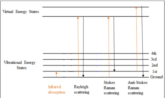
2.3.4.1 Raman Spectroscopy ... 32
2.3.4.2 X-ray Photoelectron Spectroscopy (XPS) ... 34
2.3.5 Electrical Measurements ... 34
3 Results and Discussions ... 38
3.1 Determination of Degree of Crystallinity of PP ... 38
3.1.1 Preliminary Examination by POM ... 38
xi
3.1.2.1 XRD Results ... 41
3.1.2.2 Raman Results ... 46
3.1.3 Quantitative Analysis ... 51
3.1.3.1 DSC Results ... 52
3.2 Results of Mechanical Tests... 55
3.3 Physical Investigation of Polypropylene Surface ... 59
3.3.1 AFM Results ... 59
3.4 Chemical Investigation of Polypropylene Surface ... 61
3.4.1 XPS Results ... 62
3.5 Electrical Investigation of Polypropylene Surface ... 65
3.5.1 KFM Results ... 65
3.6 Metal-Polymer (PP) Contact Electrification Results ... 68
3.6.1 Mechanism of Metal-Polymer Contact Electrification ... 69
3.6.2 The Contact Electrification of PP Before and After Treatments ... 75
3.6.2.1 The Effect of Period of Time for Microwave Radiation on Contact Electrification of PP ... 76
3.6.3 The Effect of Tapping Frequency on Contact Electrification ... 78
3.7 Non-Contact Electrification ... 79
3.7.1 The Effect of Microwave Radiation on Non-Contact Electrification of PP ... 83
xii
3.7.3 The Relation Between Crystallinity and Charge Mosaic in Non-Contact Electrification of PP at the Large Scale ... 87 4 Conclusion and Future Perspectives ... 92 Bibliography ... 94
xiii
List of Figures
Figure 1. Possible mechanisms of charge transfer, a) Transfer of an electron b) Transfer of an ion. (Copyright © 2008 Wiley. Reproduced with permission from ref
[65]) ………... 7
Figure 2. a) Working principle of iTENG, b) Typical voltage output of the iTENG. (Copyright © 2014 Wiley. Reproduced with permission from ref [82]) …..……….. 12
Figure 3. In a semi-crystalline polymer, the distribution of mixed amorphous and crystalline regions ………... 14
Figure 4. Structure of polypropylene ………... 16
Figure 5. Structure of isotactic PP ………... 17
Figure 6. Structure of syndiotactic PP ………... 17
Figure 7. Structure of atactic PP ……… 17
Figure 8. Dog-bone shaped tensile test specimen for polymers. Source: Wikipedia ……….... 25
Figure 9. a) Untreated PP film, b) Crystallization occurring on PP film is indicated by whitening of the highly stretched areas that occur after application of tensile stress (Lfinal = 325 mm) ………... 27
Figure 10. Energy-level diagram indicating the states in Raman spectrum ……… 33 Figure 11. a) Mechanical tapping device developed in our laboratory; 1) solenoid linear motor, 2) sample and electrode compartment, 3) XY positioner stage, 4) Oscilloscope channel-1 connected to polymer containing metal electrode, 5) Oscilloscope channel-2 connected to Cu electrode, b) electrodes, (i.e. SEM metal
xiv
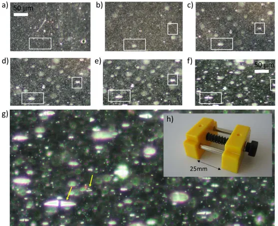
stubs), c) components of the sample holder for polymer film (PTFE is illustrated as an example), d) Fixed electrode on which polymer sample is put, e) copper electrode on a linear X stage used in the metal-polymer contact electrification experiments .………... 35 Figure 12 a) Electronic control unit for the tapping device 1) power supply of the microprocessor, 2) Arduino-nano microprocessor, 3) On-Off switch to control power supply of solenoid, 4) power supply for solenoid. b) Oscilloscope used in electrical measurements for metal-polymer contact electrification experiments ……… 35 Figure 13. Typical 2D voltage (V) versus time (s) plot obtained through contact electrification experiments ... 36 Figure 14. a) The whole representation of non-contact electrification measurement with Keithley 6514 electrometer, Faraday cage, and the mechanical tester, b) Faraday cage around PP film positioned between the grips .……… 37 Figure 15. a) The 50x magnified POM image of untreated PP, b) The 50x magnified POM image of 600 W-10 min microwave radiated PP, c) The 50x magnified POM image of mechanically treated PP with 40mm/min extension rate, d) The 100x magnified POM image of untreated PP, e) The 100x magnified POM image of 600 W-10 min microwave radiated PP, f) The W-100x magnified POM image of mechanically treated PP with 40mm/min extension rate. Arrows in c) and f) indicate the direction of stretching of the sample ………...………..……… 39 Figure 16. PP film under mechanical stress increasing from (a) to (g) and the representation of the change in crystalline structure of PP, and h) the device used in the application of mechanical stress ………... 40
xv
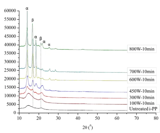
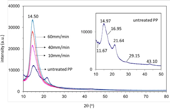
Figure 17. X-ray diffractograms of untreated and 600W-microwave treated PP samples with respect to the different period of time for radiation exposure ……… 42 Figure 18. X-ray diffractograms signals of untreated and 10min-microwave treated PP samples with respect to the different power of radiation ..……… 43 Figure 19. X-ray diffraction diffractograms of untreated PP and mechanically treated PP with different extension rates …...………. 44 Figure 20. Raman spectra of untreated and 600W-microwave treated PP samples with respect to the different period of radiation exposure time a) in the Raman spectrum range 0-4000 cm-1 b) 0-1600 cm-1 and c) the normalized Raman spectra according to the peak at 808 cm-1 in the range of 780-860 cm-1………..………. 47 Figure 21. Raman spectra of untreated and 10min-microwave treated PP samples with respect to the different power of radiation a) in the Raman spectrum range 0-4000 cm -1 b) 0-1600 cm-1 and c) the normalized Raman spectra according to the peak at 808 cm -1 in the range of 780-860 cm-1 …………...………..……… 48
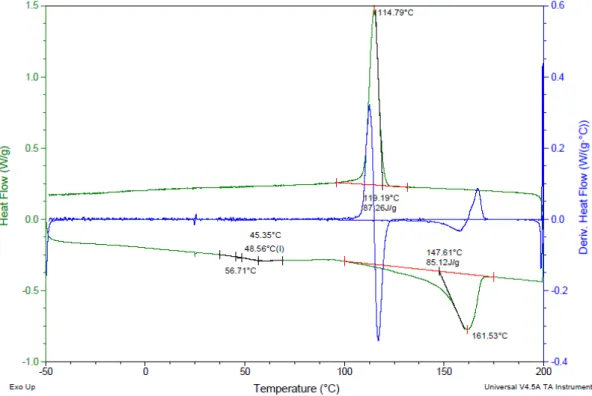
Figure 22. Raman spectra of mechanically treated PP from different points across the sample a) in the spectrum range 0-4000 cm-1,b) 0-1600 cm-1,and c) the normalized Raman spectra according to the peak at 808 cm-1 in the range of 780-860 cm-1 ……….……….….. 50 Figure 23. Raman scan image of crystalline regions in mechanically treated PP ……… 51 Figure 24. DSC curve of untreated PP (8.9 mg) with 10 0C/min in a cyclic method ………...………..………... 52
xvi
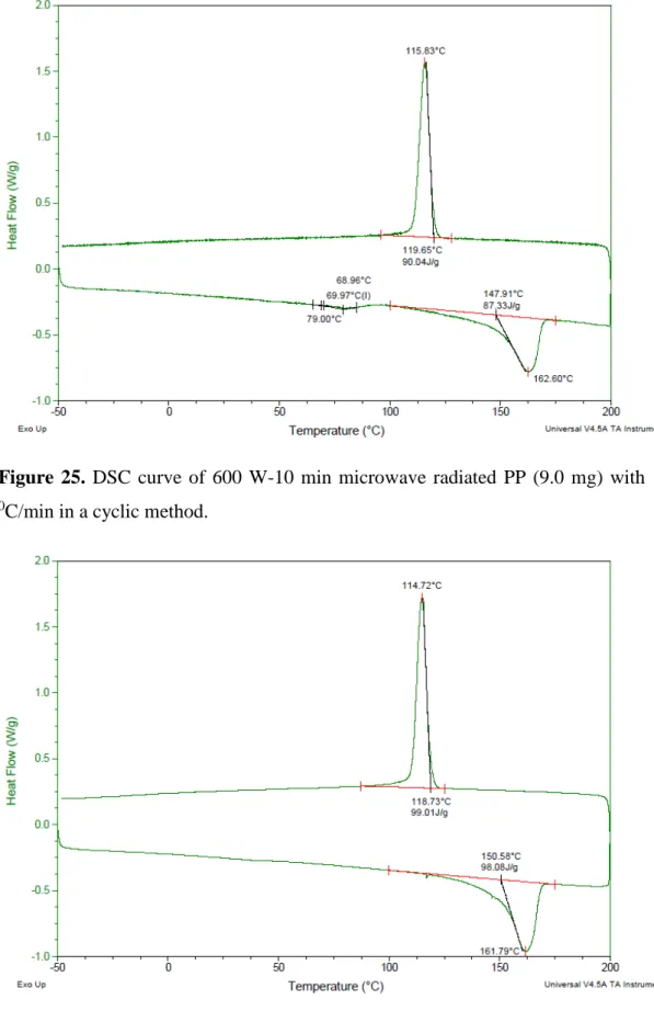
Figure 25. DSC curve of 600 W-10 min microwave radiated PP (9.0 mg) with 10
0C/min in a cyclic method .………. 53
Figure 26. DSC curve of 40 mm/min mechanically strained PP (9.0 mg) with 10
0C/min in a cyclic method ………...…………..…. 53
Figure 27. The tensile test of a) untreated, b) 600 W-5 min microwave treated, c) 600 W-10 min microwave treated, d) 600 W-15 min microwave treated, e) 600 W-30 min microwave treated PP samples with 10 mm/min extension rate ……….... 57 Figure 28. AFM height profile images with the surface roughness values (Sa and Sq) for a) untreated PP, b) 600 W-10 min microwave radiated PP, c) mechanically strained PP (extension rate is 40 mm/min) ………..……….……… 60 Figure 29. XPS survey scan of the untreated PP films ………..……… 62 Figure 30. XPS survey scan of the mechanically stretched (with 40 mm/min) PP films ……… 63 Figure 31. XPS survey scan of the 30 min-600 W microwave radiated PP films ……… 63 Figure 32. 2D (a) and 3D (b) height profile of untreated PP, 2D (c) and 3D (d) potential map of untreated PP ………...…………. 66 Figure 33. 2D (a) and 3D (b) height profile of 40 mm/min-mechanically strained PP, 2D (c) and 3D (d) potential map of 40 mm/min-mechanically strained PP ………...………. 67 Figure 34. a) The illustration of base electrode which is Cu SEM stub (in 12 mm diameter) coated with the polymer film (PP) and the metal electrode which is Cu in 6mm diameter, b) The schematic representation of the mechanical tapping device, c) The contact electrification (CE) peak with the convergent induction (Ic) and the
xvii
separation electrification (SE) peak with the divergent induction (Id) at 1 Hz tapping
frequency, d) The overall contact and separation peaks in 1 Hz tapping frequency obtaining 1 data in 2 s ………..………... 70 Figure 35. The representation of a) overall contact and separation peaks obtained from two different channels, oscilloscope 1 (Osc 1) and oscilloscope 2 (Osc 2), b) the CE and SE mechanisms on the base electrode (PP on it) which is connected to Osc 1, c) the CE and SE mechanisms on the Cu metal electrode which is connected Osc 2. (Adapted from Umar Gishiwa Musa’s M.S. thesis: “Mechanism of Triboelectricity: A Novel Perspective for Studying Contact Electrification Based on Metal-Polymer and Polymer-Polymer Interactions”) ………...….…… 71 Figure 36. The mechanism during contact a) The base electrode whose surface is covered by PP connected to the first channel, Osc1 which is grounded and the metal electrode connected to the second channel, Osc 2 which is also grounded, b) The voltage versus time plot containing the signals from base and metal electrode, c) PP surface and metal electrode is getting closer indicated by the application of positive force, +F, d) The positive and negative charges are generated during the contact of polymer and metal surface, e) The electrons (negatively charged particles) are not stable, that is they flow towards the ground that makes the metal electrode e- deficient leading to the generation of positive CE signal (1) from the metal electrode and at the same time (f) takes place, f) The electrons flow from the ground towards the base electrode that makes the base electrode e- rich resulting in the generation of negative
CE signal (2) obtained from the base electrode simultaneously with the generation of signal (1) from the metal electrode, g) The negative charges on the base electrode and the positive charges on the contacted surfaces remain for a very short time, i.e. around
xviii
nanosecond, and there is no signal observed at this moment which is indicated by point 5 in the plot, h) The electrons in the ground move towards the e- deficient metal electrode leading to the generation of negative CE signal (4) from the metal electrode and concurrently (i) takes place, i) The remaining electrons in the base electrode flow towards the ground that leads to the generation of positive CE signal (3) from the base electrode simultaneously with the generation of signal (4) from the metal electrode, j) The negative charges on the metal electrode and the positive charges on the contacted surfaces remain for a short time without any signal generation which is indicated by point 6 in the plot ……….………...……… 73 Figure 37. The mechanism during separation a) The negative force, -F, is applied to separate the contacted metal and polymer surface, b) During the separation electrons flow from the contacted surfaces towards the ground throughout the metal electrode that results in the positive SE signal (7) obtained from the metal electrode and at the same time (c) occurs, c) The electrons move from the ground to the base electrode that leads to the generation of negative SE signal (8) from the base electrode simultaneously with the generation of signal (7) from the metal electrode, d) After the separation, due to the bond breaking and subsequently material transfer (+) and (-) charges are recorded on the polymer and metal electrode surface at nC scale, e) When the system is left after the separation, charge decay is observed that yields decrease in the amount of charge on the polymer surface, f) After the grounding both polymer and metal surfaces lose their charges leading to the recording of zero charge ……….… 74 Figure 38. The measurement of static electrification (data/1s) for the constant tapping of Cu electrode with 1.0 Hz frequency onto a) untreated PP, b) 600 W-10 min
xix
microwave radiated PP, c) with 40 mm/min extension rate mechanically treated PP (26
0C, 18.66 % RH) ……….……….………...…… 75
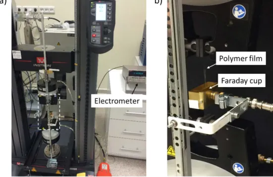
Figure 39. The measurement of static electrification with data/1s (left) and data/50ms (right) for the constant tapping of Cu electrode with 1.0 Hz frequency onto a) untreated PP b) 600 W-1 min microwave radiated PP c) 600 W-2 min microwave radiated PP d) 600 W-5 min microwave radiated PP e) 600 W-15 min microwave radiated PP f) 600 W-30 min microwave radiated PP (26.5 0C, 17 % RH) .………...……….…… 77 Figure 40. The measurement of static electrification with data/1s (left) and data/50ms (right) for the constant tapping of Cu electrode onto untreated PP with a) 1.0 Hz frequency, b) 3.0 Hz frequency, c) 5.0 Hz frequency, d) 10.0 Hz frequency (25 0C, 18.05 % RH) ………..……… 78 Figure 41. a) Presentation of the brass-made Faraday cage used throughout non-contact electrification experiments, b) Charge, q, flows between the inner and middle brass components of the Faraday tube to compensate for the enclosed charge on the material. Measuring the charge on the electrometer as a function of time will indicate the value of q. [124] ………..……….…… 80 Figure 42. a) The plot of tensile stress versus time from mechanical tester during tensile extension with 40 mm/min extension rate for untreated PP sample, b) The plot of charge versus time from the mid-point of the original untreated PP during tensile extension with 40 mm/min, c) The typical plot of partial charge distribution for the extended PP after tensile extension with 40 mm/min (25 0C, 22 % RH) …………... 81
Figure 43. a) The plot of charge versus time from the mid-point of the original untreated PP during tensile extension with 40 mm/min, b) The partial charge
xx
distribution of the extended PP after tensile extension with the rate of 40 mm/min (26.1
0C, 31 % RH) ………...…….….. 82
Figure 44. a) The plot of charge versus time during tensile extension with 40 mm/min from the mid-point of the original 600 W-10 min microwave-radiated PP after 40 min relaxing time, b) The partial charge distribution of the extended microwave-treated PP after 40 min relaxing time, c) The plot of charge versus time during tensile extension with 40 mm/min from the mid-point of the original 600 W-10 min microwave-radiated PP after ~4 hrs relaxing time, d) The partial charge distribution of the extended microwave-treated PP after ~4 hrs relaxing time (26.1 0C, 31 % RH) …..…..….….. 84 Figure 45. a) The plot of charge versus time from the mid-point of the original untreated PP sample during tensile extension with 40 mm/min, b) The partial charge distribution of the extended PP after tensile extension with 40 mm/min, c) The plot of charge versus time from the mid-point of the original untreated PP sample during tensile extension with 60 mm/min, d) The partial charge distribution of the extended PP after tensile extension with 60 mm/min, e) The plot of charge versus time from the mid-point of the original untreated PP sample during tensile extension with 80 mm/min, f) The partial charge distribution of the extended PP after tensile extension with 80 mm/min (24.5 0C, 26.0 % RH) ………..………....….... 86 Figure 46. Raman spectrum of untreated PP with the indication of the peaks that are concerned in terms of crystallinity ………..………..……….… 88 Figure 47. a) The Raman intensity ratio of the peaks at 808 cm-1 and 841 cm-1 (I
1/I2)
versus distance after the application of mechanical stress to PP film, b) The superimposed plot of the partial charge distribution and I1/I2, c) The Raman intensity
xxi
application of mechanical stress to PP film, d) The superimposed plot of the partial charge distribution and I3/I4, e) The Raman intensity ratio of the peaks at 2953 cm-1
and 2880 cm-1 (I
5/I4) versus distance after the application of mechanical stress to PP
film, f) The superimposed plot of the partial charge distribution and I5/I4
xxii
List of Tables
Table 1. Diffraction peaks of the i-PP samples [116-118] ………... 42 Table 2. Average values of Tensile Stress at Yield Point and Modulus for untreated and microwave treated PP samples ……….…….. 59 Table 3. The atomic % ratio of oxygen (O) to carbon (C) obtained from XPS ….... 64 Table 4. a) The ratio of intensity of the crystal peak at ~808 cm-1 (I1) to the amorphous
peak at ~841 cm-1 (I2), b) The ratio of intensity of the peak at ~2837 cm-1 (I3) to the
peak comes around 2880 cm-1 (I
4) and the peak at ~2953 cm-1 (I5) to the peak comes
at ~2880 cm-1 (I4) that belong to the vibrational assignment of C-H bond in CH3. [116]
xxiii
List of Abbreviations
PP : Polypropylene
ESD : Electrostatic discharge
TENG : Triboelectric nanogenerator
Tm : Melting temperature
Tg : Glass-transition temperature
PE : Polyethylene
LDPE : Low-density polyethylene
HDPE : High-density polyethylene
Lо : Gauge length
L : Total length
W : Width
POM : Polarized Optical Microscope
AFM : Atomic Force Microscope
KPFM : Kelvin Probe Force Microscope
XRD : X-ray Diffraction
DSC : Differential Scanning Calorimetry XPS : X-ray Photoelectron Spectroscopy
Q : Charge
nC : Nanocoulomb
ms : Millisecond
xxiv h : Hour σy : Yield strength σ : Stress ε : Strain EL : Elongation Cu : Copper RH : Relative humidity CE : Contact electrification SE : Separation electrification Ic : Convergent induction Id : Divergent induction
1
Chapter 1
Introduction
1.1 Overview of problem in triboelectricity
Tribology focuses on the friction, lubrication and wear of the interacting surfaces which are in a relative motion. [1] One very closely related field to this well-known engineering and science concept is tribocharging or triboelectricity. [2] Tribocharging is a very common phenomenon and it is observed very often in our daily lives e.g. a piece of wool is get charged and attracts some other materials when it is rubbed, or an air balloon attracts other materials or can be held by the ceiling for some time when it is rubbed against e.g. a piece of paper or hair especially in a dry day. However, generation of charges during the tribocharging event by some mechanical means such as sliding, rubbing, or contact is not fully understood and many questions have not been answered yet regarding clarification of the charge generation mechanism. For example, the source of electrons in tribocharging is still unclear if the mechanism is based on the electron transfer for insulating materials? what is the fundamental reason for a better charging in a dry atmosphere? why the charging is very low in an inert atmosphere? how is it possible to light a lamp without electrons regarding ion-transfer mechanism? why different materials charge differently? Nevertheless, various research groups working on this field indicated that physical, chemical and mechanical properties of the materials and external conditions effect the tribocharge formation. Therefore, we believe that the investigation of the physical properties of the materials and the correlation between these properties and
2
triboelectric charge generation would be a very good starting point to understand the fundamentals of the problem in tribocharging.
1.1.1 Historical Development of Triboelectricity
When two materials are brought into physical contact and separated, charging occurs and this phenomenon is called as ‘contact electrification’. [3-15] Albeit, it is more obvious for the contact of insulator materials owing to their ability to retain the charge for a long time. Without considering the contact electrification, the practical applications of friction appears in pre-historical times when the man use the frictional heat for lighting of fires. [16] On the other hand, the origin of tribology studies is based on the experiments of Thales of Miletus, a pre-Socratic Greek philosopher, showing that the electrostatic charging is caused by rubbing amber against wool, and this is the preliminary demonstration of ‘triboelectric’ effect that means ‘rubbing amber’ in Greek. [2] Later, William Gilbert (1544 – 1603) focused on the ‘amber effect’ and he found out that different materials other than amber attract each other when they are rubbed. After the first indications on electrostatic charging related with the charging behavior of amber as a result of friction, Gilbert states "There is in amber something flame-like, or having the nature of the breath and this, when the paths are cleared by friction of the surface, is emitted and attracts bodies" as a quotation from Plutarch (c46-120) who was another Greek philosopher. [17] Then, with the observation of Gilbert around 1600, this effect was called as ‘electric’ coming from elektra, which is used for ‘amber’ in Greek. [18] As it was hypothesized in seventeenth century by Cabeo, Digby, Gassendi, Descartes, Boyle, and Newton several charging mechanisms were proposed, subsequently considerable increase of the interest towards the
3
experimentation in electrostatics was observed. [19-21] However, the complexity of the subject still remains to date. The subsequent studies in this concept came from Benjamin Franklin who made the distinction between positive and negative charges in 1740 and Faraday who analyzed the frictional electricity of steam and water against other materials. [18, 22-24] Later on, substantial experimental and theoretical electrostatic studies were carried out by Coulomb, Maxwell, Faraday, Volta, Tesla, Kelvin, Rutherford and Bohr, and the results of all these early stage studies were supported by Maxwell’s Treatise. [25]
1.1.2 Examples of Contact Electrification
Contact electrification and dispersal of static charge has a considerable importance in today’s technology when considering the manufacturing electronic devices, fabrics and applications of polymeric films in many different fields (auto industry, space applications, textile etc.). In other words, contact electrification or triboelectrification process occurs for insulating materials has a dramatic practical importance. Consequently, the wide range of polymer use and its tribocharging due to contact or friction makes the better understanding of this phenomenon necessary. As a result, the subject has caught academic and industrial interest to a great extent nowadays. As it is indicated by Baytekin et al. the increasing demand for polymers, that is 454 billion $ for now and 567 billion $ for 2017, and the use of polymers in electronic device components, also in terms of the size of chips that is getting smaller and smaller makes the triborcharging of polymers and charge dissipation becomes a much more important issue. [26] On the other hand, tribocharging has considerable negative side effects whereas its useful applications are present in technological
4
devices. Since it is hard to get rid of electrostatic discharge (ESD) despite it can be generated easily there are numerous problems are observed in industry, for instance in the fabrication of synthetic films or fibers as they cling on the machinery parts due to the charging that cause the working of the production line stop. [27] As it is pointed out, common hazardous way of tribocharging experienced in industrial processes of fiber spinning, tanker explosions due to the ignition of explosive vapors or defects in the fabrication in photographic films. Yet, the helpful use of tribocharging in applications are widespread, such as xerography, electrostatic spraying or electrostatic separation in the recycling industry and so on. [5, 28-30]
In terms of the examples of contact electrification (i.e. triboelectrification) there are so many areas from electronics to pharmaceutics. Thus, a few of them are covered here.
• Undesirable explosions: When the charge is built-up on the surface of material as a result of contact electrification, it causes sparks that can lead to serious explosions in the presence of any flammable material in the environment. In particular, these kind of explosions are very crucial for granular systems, such as pneumatic conveying and fluidized bed processes. [31-33] Large surface to volume ratio of these highly dispersed particles leads to increase in the area of contact and accumulation of significant amount of charge that cause the combustion during the charge dissipation to the air containing oxygen. [34, 35] • Xerography (Electrophotography): Whole electrophotographic devices’ (e.g. laser printing, photocopying) working principle relies on the contact charging. The toner particles are charged by rubbing them against metal beads that leads
5
to the attraction of toner particles to corona-charged drum. As a result of patterning, the process is completed. [36, 37]
• Separation of mixed granules: In industrial applications, triboelectrification is utilized as a charging technique in order to sort the mixed granular insulators. The devices used for this purpose are called triboelectric separators. [38-40] • Space industry: The importance of contact charging is apparent in space
applications because many dust storms are known to occur in Moon and Mars, which are much greater than those on Earth that leads to significant amount of charging among the dust particles. Consequently, the electric fields resulting of charged particles which adhere to the astronauts’ spacesuits and spaceships can cause serious problems in electronic and mechanical equipments. [41-45] • Pharmaceuticals: In the production of pharmaceutical chemicals, the powder
form is used in the process and contact charging arises during the flow of particles. Due to the electrostatic charge that occurs during the process, problems in the uniformity of blending (i.e. segregation, agglomeration) and non-homogenous dosages are observed. [46-49] Moreover, in pharmaceutical devices using for dispersion purposes, such as dry powder inhalers (DIP) triboelectrification can cause negative effects on the way of introducing particles into the body. [50]
• Electronics: In the electronic devices, with the result that contact charging excess amount of charge is built-up on the components, then ESD occurs which causes serious damages on the electronic parts. Therefore, controlling and preferably eliminating the contact charging is a need for manufacturing of electronic devices. As it is stated in Intel Packaging Data Book, approximately
6
12000 V of static electricity can be generated by just walking on the vinyl floor which is much greater than the charge that is enough to cause a damage a standard Schottky TTL component. [51]
1.1.3 The Mechanism Behind Contact Electrification
There have been significant efforts to understand the mechanism of contact electrification even though the phenomenon itself is known for decades. In particular, understanding the mechanism behind the contact electrification for insulators (e.g. polymers) is much more complex than for metals. The main reason for this is because the gap between the filled valence band and the unfilled conduction band is much greater than the possible thermal energy in insulators that hinders the electron transfer. [3] On the other hand, contact electrification between two metals that is based on the difference in work functions is considered to be more straightforward than insulators. In metals, there are partially filled electronic states containing vacant conduction states and occupied valence states that are infinitesimally higher in energy than the vacant conduction states. The highest occupied energy state of the valence band is defined by the Fermi level or work function (i.e. the energy needed so that an electron can be removed from the surface). Hence, the contact electrification mechanism of metal surfaces relies on the electron transfer from the material having lower work function (i.e. larger Fermi level) to the material having larger work function (i.e. lower Fermi level). [3, 52] As a result, present difference between the Fermi levels of metals facilitates the electron transfer during the contact of metal surfaces. Possible tribocharging mechanisms via transfer of an electron and transfer of an ion for materials that are made of metal and insulator are depicted in Figure 1.
7
Figure 1. Possible mechanisms of charge transfer, a) transfer of an electron, b) transfer of an ion. (Copyright © 2008 Wiley. Reproduced with permission from ref [65]).
• Electron exchange: The gap separating unfilled conduction band and filled valance band is much larger than the available thermal energy in insulators. Hence, an electron cannot be moved into the valence band as it is filled and it cannot be moved into the conduction band because much higher energy is needed. [3] As a result, electron transfer seems thermodynamically not favorable for insulators. However, there are defects or so-called “trap” states located in the band gap are which partially resided by electrons that are not in their lowest energy state (i.e. not in the stable state). Hence, the magnitude of charge transfer and the resulting sign on the contacted materials depend on the density of these states and the ability of transfer between the states which are at different energy-level.
8
The existence of trapped electrons which are described as non-equilibrium electrons are remarked by Truscott and Lowell. [53] Later, by the thermoluminescence and phosphorescence analysis they observed that the trapped electrons may persist in high energy level for a long time. [54-56] Thus, the conductivity that provides contact charging in insulators is the result of the existence of these trapped electrons. In order to enlighten the reason for why the trap states containing non-equilibrium electrons appear it has been suggested that the chemical and conformational defects leads to the occurence of these states. [57-59] Another proposed explanation is that the interaction of material surfaces during the contact forms these states. [60, 61] It is pointed out by Seanor that the observed behavior as a consequence of traps may be because of the disorders present in the polymer structure that can be due to the impurities left over from the manufacturing process. [24] Furthermore, as it is stated by Mort et al. even present oxygen in the environment can play a significant role for the electronic transfer and contact electrification in terms of low conductivity polymers. Also, adsorbed molecules or the products formed as a result of the interaction between atmospheric molecules and the polymer surface can change the way of electron transfer, subsequently contact electrification. [6, 10, 11, 62, 63] Therefore, the nature of the process for the electron transfer in polymers remains elusive and the parameters that affect the charging are various.
• Ion exchange: There are polymeric systems whereby ion transfer leads to the conductivity and electrification. This mechanism is related with the polymers containing ions, such as polyelectrolytes and ionomers. It leads to the ionizing
9
with the help of present structural groups that are capable of ionization. The mechanism works in such a way that when two materials that have loosely bound ions and counter ions (i.e. strongly bound) in different polarities the loosely bound ions transfer to the other surface, leaving the host surface with a net charge of the strongly bounded ions. As Diaz and Guay indicate that ionic transfer for the materials containing ionomers is based on correlations between the sign of the charge transferred and the sign of the mobile ion species on the surface the beads taking place in the charge transfer. [64] Hence, ion transfer is proposed as the mechanism for contact charging if salts with mobile ions are present in the polymer.
• Material or Mass transfer: During the contact charging between polymers provides mass transfer at the same time. It is suggested by Baytekin et al. that ‘mosaic’ patterns of charging occur because of the material transfer driven by bond breaking which leads to the heterogeneous alterations on the polymer surface. They revealed the charge mosaics by Kelvin Force Microscopy (KFM) that presents information about the surface charge and confirmed the presence of material transfer with X-ray Photoelectron Spectroscopy (XPS). [66] Thus, during the material transfer between the contacted polymer surfaces bond-breaking and bond-forming take place simultaneously where the atomic-scale changes on the surfaces occur. As it is indicated by Salaneck et al. the non-destructive XPS technique makes it possible to detect the material fragments on the polymer surface after the material transfer occurs during the contact. [67]
10
In addition, by using XPS technique Piperno et al. showed that the ability of surfaces to adsorb ions differs in addition to material transfer during the contact of two materials. [68] Consequently, about contact charging it can be said that it is not directly based on only the material transfer, but also on the changes of surface properties. Furthermore, it is considered that for the bond-breaking and bond-forming processes both electronic and ionic transfer mechanisms are involved.
• Mechanochemical transfer: In addition to material transfer during the contact electrification of polymers, also radicals are produced as a result of rupturing in chemical chains. These free radicals which are formed because of mechanical stress is called ‘mechanoradicals.’ If the bond-breaking is homolytic a pair of radicals is formed whereas if it is heterolytic scission then a negative or positive ion pair is formed. [51] Thus, the electrons released by mechanoradicals or ions released by heterolytic bond cleavage are transferred between the contacted surfaces resulting with the net charging of polymers. It is considered that there is no single mechanism that reveals triboelectrification (or contact electrification as a special case). Nonetheless, all mechanisms revised above play a part and it is supported by various spectroscopic experiments that the contact which creates stress on the polymer surface produces electrons, ions, and radicals. [69-73] Our research is based on the electrification in polymers, the mechanism behind the contact electrification will be discussed for insulators in the following subsections.
11
1.1.4 Triboelectric
Energy
Harvesting
Based on Contact
Electrification
In this part, polymer-based triboelectric (or electrostatic) generators will be discussed. Since our experimental results are focused on the tricoelectrification of Polypropylene (PP), investigation of the practical or technological use of polymers is important. When today’s worldwide problem related with the energy supply is considered, energy harvesting draws intense attention. In this respect, mechanical energy, owing to its abundant availability, is an ideal source that can be benefit from in order to tailor to our needs for energy supply.
When electrostatic generators are taken into account, contact electrification is the base for working of these mechanical devices. On the other hand, materials that have ability of strong triboelectrification effect are less conductive or insulators (e.g. polymers), hence they can retain the charge for an extended period of time. [74] The working principle that tribogenerators rely on is that the contact-induced electrification whereby the materials with different tribo-polarity become electrically charged through contact-separation or relative sliding against each other. When two different materials brought into contact, charging via electron, ion, radicals or material transfer occurs. The most popular tribogenerators are the Van de Graaff and Wimshurst generator, which were invented 1929 and ~1880, respectively. [26, 74, 75] These machines use the accumulated static charges generated by triboelectrification and generates high electric fields to accelerate particles. In addition to mechanical energy harvesting, the other application of tribogenerators is their use of as a self-powered active sensors because they do not need any external source of power to drive. [74, 76] Besides, harvesting energy for nanosystems has been developed nowadays, then
12
triboelectric nanogenerator (TENG) is commercialized that is considered to be an outbreak in academy and technology. Subsequently, there are many research going on by chemists and materials scientists to increase energy density in TENGs through altering the materials or their morphological properties. [77-81] The mechanism of the TENG can be explained as a combination of electrostatic induction with the conjunction of triboelectrification. As it can be seen in the following schematic representation the fabrication of the implantable TENG (iTENG) is based on the design of a fully packaged structure.
Figure 2. a) Working principle of iTENG, b) Typical voltage output of the iTENG. (Copyright © 2014 Wiley. Reproduced with permission from ref [82]).
It is obvious that channeling the available, however wasted mechanical energy into the power source in order to meet the need of energy supply problem is significantly important. Despite there are various useful technological applications of converting mechanical energy to electricity by contact of insulators, we observed that it is also possible to produce electricity without any contact, but by just applying mechanical stress to a polymer film. The novelty of our study is in the investigation of
13
practical energy harvesting and to gain a control on the electrification by altering the physical parameters of the material (i.e. degree of crystallinity, roughness). The experimental details and results will be provided in the following sections.
1.2 The Effect of Physical Properties of Materials in Tribocharging
Physical properties of polymers play a crucial role on mechanical strength of polymers when the industrial applications are taken into account. Recent studies showed that these properties can also have high effect on the generation of charge and thus on electrification of polymers. For example, change in elastic properties can determine the charging behavior of two contacting polymeric materials. [14] However, the relation between the polymer structure, which has a big influence on the determination of physical properties, and the triboelectrical properties has not been studied in detail and remains still unclear. In this study we modified the structure of PP and investigated the relation between its physical properties and its tribocharging behavior by using various spectroscopic and microscopic techniques. We think that the outcomes of this study will be one of the milestones for the fundamental research in tribology and hopefully our results will be considerably useful to solve industrial problems arising from tribocharging.1.2.1 Polymer Crystallinity
In the macromolecular polymer structure, the polymer chains can be highly ordered (crystalline regions) or can be in random coil orientation (amorphous regions). The crystallinity degree is determined by the volume percentage of crystalline regions corresponding to the total volume in the polymeric structure. Moreover, the degree of
14
crystallinity can change from polymer to polymer, even for the same polymer it can alter because of different treatments of the polymer or due to the differences in the production of polymers. To illustrate, the differences in crystallinity for the same polymer may arise from factors, such as melting and cooling rate, pulling speed or stress applied during pulling of fibers that influence regularity of the polymeric chains during the fabrication process. [83-85] Therefore, depending on the process conditions different % crystallinity can be obtained. In Figure 3 the distribution of crystalline and amorphous regions is depicted schematically.
Figure 3. In a semi-crystalline polymer, the distribution of mixed amorphous and crystalline regions.
The well-ordered crystalline regions are also called ‘crystallites’ in which the polymer chain segments are oriented regularly with respect to each other, see Figure 3. [83, 86] Between these well-ordered crystallites there are irregular regions, which have random-coil orientations having amorphous character. The degree of crystallinity plays a significant role in the determination of polymers’ physical and mechanical properties, such as its melting temperature (Tm), glass transition temperature (Tg),
15
polymers have the same chemical formula, if their crystallinity degree differs, their physical, mechanical, optical, thermal, electrical properties may be different. Hence, crystallinity becomes highly important when different areas, applications or purposes are considered in the use of polymers. For the determination of the degree of crystallinity, Differential Scanning Calorimetry (DSC), X-ray Diffractometer (XRD), Raman Spectroscopy were used in our study (see Characterization Techniques in Chapter 2). In this thesis, our main approach is that to combine structure and physical properties of PP with its mechanical and tribological behavior. Hence, we investigated the effect of polymer crystallinity on its mechanical and electrical features so that the results can be used for both scientific and industrial purposes.
1.2.2 The Relation Between Crystallinity of Polymers and their
Triboelectrical Aspects
It was demonstrated in previous studies that the oxidation and morphology of materials’ surfaces are the important parameters that cause alterations in their contact electrification. As it is indicated by Li et al. surface roughness can considerably change materials’ electronic properties, then it controls the extent of contact between two surfaces. [51, 87, 88] In addition to this indication, it is stated that there is a correlation between surface roughness and charging by Coste et al. and Ohara et al. [89, 90] On the other hand, no clear link has been established between crystallinity and electrification. In our experiments, charge increased as the degree of crystallinity decreased. Although the alterations in physiochemical properties of a material surface in terms of the charge transfer has been investigated in many studies, the effect of crystallinity in contact electrification could not draw attention. However, the results of
16
our research show that physical properties of polymers, especially crystallinity, has a significant role as it controls the surface roughness and the extent of contact electrification.
In this thesis, crystallinity of PP samples treated with different experimental techniques (i.e. microwave radiation and mechanical stress) were analyzed. After the investigation of changes in crystallinity for PP samples through the treatments, triboelectrical properties of these samples were analyzed. As different degree of crystallinity leads to the changes in a way of charge transfer, considerable alterations in triboelectrical aspects of the samples were observed. Besides, the reason for different behavior of the samples which have different degree of crystallinity in the contact and non-contact charging needs to be understood. Then, the results which will be obtained from the experiments in this field can be used in various applications of polymers in which static electrification has a notable importance.
1.3 Polypropylene
Polypropylene (PP) is a thermoplastic polymer, which is formed by the polymerization of propylene monomers into the long PP chains. The chemical formula of PP is (C3H6)n and its structure can be designated as in Figure 4.
17
In 1954, with the successive work of K. Ziegler and G. Natta the first PP was produced by the polymerization of propylene monomers. Later, in 1957 the most widely used form of commercial PP was produced by Montecatini through the linkage of monomers with the help of Ziegler-Natta catalysts (i.e. Al and Ti based catalysts) that leads to the crystallizable chains. [83, 91, 92] The orientation of the methyl groups (CH3) during the linking of monomer molecules brings the concept of tacticity into the
consideration. If all the methyl groups are on the same side across the backbone chain, it is called isotactic PP (see Figure 5). If the pendant methyl groups are attached to the backbone chain in an alternating manner, it is called syndiotactic PP (see Figure 6). A PP structure, where the methyl groups are positioned in a random manner on the polymer backbone chain, is referred to atactic PP (see Figure 7).
Figure 5. Structure of isotactic PP.
Figure 6. Structure of syndiotactic PP.
18
When the isotactic PP is considered the methyl groups would be expected to inhibit the packing of the chains. However, these pendant groups (CH3) impose a
helical twist on the backbone of the polymer, then crystallization can occur. The helical structures can pack to form crystal. On the contrary, the atactic PP does not form a helical structure and crystallization is hindered. As a consequence, atactic PP is a soft, flexible solid and is used as an additive to lubrication oils, whereas the isotactic PP is rigid and used for fabrication of hot water pipes in plumbing applications. [93]
In a wide-range industrial use of PP, it is reported that the most commercial form is isotactic PP that has the required properties for a useful plastic material, as isotactic PP is crystallizable, while atactic PP is noncrystallizable. [91] Thus, the relative orientation of the pendant groups against each other is significant in terms of the PP’s ability to form crystals which is important in the determination of physical and mechanical properties.
1.3.1 Structure of Polypropylene
PP is a linear hydrocarbon polymer that at first glance approximately resembles polyethylene (PE) which makes PP and PE share many similar properties including electrical behavior. [91] However, the existence of pendant methyl group varies the properties of PP in many ways from PE. For instance, it makes PP chains stiffer and its melting temperature higher even though there is reduction of symmetry in the polymeric chain. In addition, because of pendant methyl groups the tensile strength and modulus of PP are higher compared to PE. On the other hand, the physical, thermal, and mechanical properties of PP can vary by its tacticity, % crystallinity, molecular weight and its distribution. [91] The important parameter for our study is
19
the percent crystallinity, which is originated through the amount of crystalline and amorphous regions formed by the polymer chains, has significant impact on the physical properties of PP.
The linearity of molecular chains in PP gives an ability to form ordered crystal structure in a way that the chains are packed regularly. However, in some regions the chains may be entangled leading to forming of branches that makes the structure not perfectly regular. Therefore, PP is defined as a semi-crystalline polymer consisting of crystalline and amorphous segments.
In the determination of percent crystallinity and crystal structure, thermal history on the polymer is important that the working principle of thermo-analytical devices is based on (see Characterization by Analytical Techniques section in Chapter 2). As the crystallinity increases density, hardness, modulus, barrier properties, wear and abrasion resistance of the polymer increase, too. On the other hand, when the crystallinity decreases better transparency (advantage for packaging), capability of good thermoforming and good processibility are obtained. [91]
1.3.2 Basic Properties of Polypropylene
Polypropylene is a viscoelastic material, like other thermoplastics. In other words, it exhibits both viscous material’s property (i.e. resistant to shear flow and strains in a linear way according to time when stress is applied) and elastic material’s property (i.e. quickly returns its original state when the stress is released). Hence, the viscoelastic behavior of PP is described with a strain rate dependence on time that makes the mechanical properties of PP time and stress related. [91, 94]
20
1.3.2.1 Density
The density of polypropylene is between 0.895 and 0.92 g/cm3 and typical density of isotactic polypropylene (i-PP) is 0.9 g/cm3 which makes i-PP the lightest viscoelastic material among the widely used thermoplastics. This feature of i-PP provides the manufacturers with the advantage of constructing many items easily. [91]
1.3.2.2 Mechanical Properties
The mechanical strength of PP is closely related with its degree of crystallinity. As the crystalline phase of semi-crystalline PP maintains mechanical strength, it has high tensile strength, hardness, and stiffness which are the main interest of product design engineers. Albeit, increase in molecular weight causes decrease in its tensile strength, hardness, and stiffness while that leads to the raise in impact strength of PP. [91, 95]
1.3.2.3 Electrical Properties
PP is a good electrical insulator whereby it is a nonpolar hydrocarbon. As it was stated before in Structure of Polypropylene section, PP is in a good similarity with PE in terms of electrical aspects. To clarify, the dielectric strength (i.e. a measure of dielectric breakdown resistance under an applied voltage) of PP is 28 MV/m whereas it is 27 MV/m for low-density PE (LDPE) and 22 MV/m for high-density PE (HDPE). Additionally, the volume resistivity (i.e. electrical resistance when an electrical potential is applied) of PP is 1017Ω cm while it is 1016Ω cm for LDPE and 1017Ω cm
for HDPE. [96] In general, PP exhibits low dielectric constant and significantly high electrical resistivity and a good material for electrical insulation.
21
1.3.2.4 Thermal Properties
In the use and processibility of polymers, their response to the temperature changes is important as their physical, chemical, and electrical properties are very sensitive to temperature. The mechanical properties of PP is mainly determined by its crystallinity and glass transition temperature (ie. the temperature at which the material changes from a glassy hard state to a soft state).The second-order glass transition temperature of PP is -10 0C (predicted). The actual value can be found in the range of 0-20 0C that depends on the rate of heating. Further, its crystalline melting point is in between 160-170 0C and recrystallization temperature is found in the range of 115-135
0C with the slow cooling rate of the melt. [91] Different morphological forms of PP
shows different melting behaviors. For example, beta form of PP which has a hexagonal unit cell melts at 152-155 oC, and monoclinic alpha phase melts at higher, 165-168 oC. These two forms of PP have their characteristic XRD signals.
1.3.3 Applications and Importance of Polypropylene
PP has a high-volume usage in industry due to its excellence in physical, thermal, and mechanical properties. First of all, it is a low-cost engineering plastic. Its resistance to higher temperatures and high stiffness at low density are the key characteristics of PP. Secondly, it offers good chemical and fatigue resistance, good hardness, good external stress cracking resistance and ease of machining, together with good processibility that makes PP highly important and requested among the commonly used commodity materials. Its high flexibility, low density, and resistance to corrosion make PP the material of choice for many applications. [91, 97]
22
Some of the main applications of PP are the household items (bottles, bottle caps, buckets, bowls, luggage etc.), packaging (films, blister packaging, strapping tapes, thin-walled packaging for disposable food trays etc.), automotive industry (wheel arch liner, steering wheel covers, radiator expansion tanks, brake fluid reservoirs fittings, bumpers etc.), pipes and fittings (hot wire reservoirs, domestic waste water pipes, heat exchangers, solid rods etc.), domestic appliances (microwave oven cabinet, refrigerator components, dishwasher and washing machine parts etc.), fibres (filament yarns, artificial sport surfaces, woven carpet backing, monofilaments for rope etc.), furniture (stackable chairs etc.) and so on. [91]
It was reported that “the total worldwide demand for PP has currently reached an amount of approximately 47 million tons (prediction for 2008)” and this number has reached 55.1 million tons in 2013 remaining increase in the worldwide market by 5.8 % per annum until 2021 according to the Market Study: Polypropylene (© 2016 Ceresana). [98]
1.4 Techniques used in the Characterization of Polypropylene
In our research, various spectroscopic and microscopic techniques were used in order to analyze the polymer (i.e. PP films) surface in terms of physical and chemical properties, also to investigate the triboelectrification behavior electrical mesaurements were carried out via our home-made tapping device and oscilloscope. Main characterization techniques that we have used in this study are X-ray Diffractometer (XRD), Raman, Differential Scanning Calorimetry (DSC), Polarized Optical Microscope (POM) in order to analyze the crystalline property of PP and Kelvin Probe Force Microscopy (KPFM) to investigate the surface distribution of electrical
23
potential, also X-ray Photoelectron Spectroscopy (XPS) for the analysis of surface chemistry. The detailed information about the instruments and their usage purposes will be presented in Chapter 2, under Characterization Techniques.
1.5 Motivation and Goals of the Thesis
Static electrification and dissipation of the generated charge is of great importance when considering the applications of polymers in a wide-range of fields (e.g. from electronics to textile industry). In order to fabricate new technological devices by taking an advantage of tribocharging and to find exact solutions to the problems related with static electrification occurring in the practical use of polymers, in the first step there is a need to investigate the physical and chemical properties of polymers multi-dimensionally. Therefore, the relations of these properties with their triboelectrical behavior needs to be understood by using modern analytical characterization techniques.
In this thesis, our main goal is to reveal the effect of crystallinity for PP on its static electrification. The reason for why we selected PP is that its hydrophobic nature tends to relatively slow charge decay that facilitates the measurement of generated charge on film surface. [99] Crystallinity is one of the major parameters that determine the physical properties of polymers, therefore, it plays a crucial role in polymer science and technology.
1) This study makes a difference as it proves the fact that changing the degree of crystallinity and the physical properties of the polymer (e.g. mechanical strength, surface roughness, etc.), it is possible to obtain different triboelectrical behavior that gives an opportunity to gain a control on the
24
polymer’s triboelectrical charging. As a result, it would be possible to reduce the static electrification of a commercially available material by a single change in its physical property through the application of mechanical stress which leads to outstanding alteration in the crystallinity and surface roughness of a material.
2) We motivated also to show that it is possible to generate electricity from a polymer just by applying mechanical force to the polymer film. As a consequence, the results will serve the valuable information for the fabrication of more efficient tribo-electric generators.
3) Another goal to conduct this research is to verify if the formation of a mosaic of nanoscopic patches of positive and negative charges can also exist on large scale after the application of mechanical stress onto polymer film.
4) It was aimed to deeply understand the mechanism behind the static electrification of a polypropylene so that it would be possible to monitor and control its triboelectric charging which will be very helpful in the practical use of polymers in both industrial, scientific and technological essence.
To sum up, the lack of knowledge in literature in terms of understanding the mechanism and the relation between crystallinity of a polymer and its tribocharging property has led and motivate us for conducting this research.
25
Chapter 2
Experimental
2.1 Materials
The specimens that were used throughout our research were commercial isotactic polypropylene, i-PP, (see also the characterization results from XRD, Raman, and DSC in Chapter 3). For the tensile tests, standard-sized dog-bone shaped PP samples which were obtained from Colorito item no: Colkapka were prepared by the die cutting machine (Model: MULTI-DIE CUTTING, Serial Number: MDC2015058) so that the specimens (whose gage length, Lо = 40 mm, total length, L = 114.6 mm, width, W = 6 mm, thickness = 0.0476 mm) could suit the technical specific standards. Thus, the obtained samples follow “Type A” standards (i.e. Generic Safety Standards) which are described as UNI EN ISO 12100-1 and UNI EN ISO 12100-2.
26
2.2 Experimental Procedure
In the experimental procedure, in order to differentiate % crystallinity of untreated PP films two procedures were applied. First treatment was microwave irradiation and the second treatment was application of mechanical test or tensile stress.
2.2.1 Microwave Radiation
In this part of the experiment, samples in the same standard shape were positioned as equally far from the center of the rotating table in a kitchen microwave oven (Samsung, Model: MS23F301EAW). It is important for the samples to be located perfectly symmetrical against each other (i.e. in equal distance to the center of the table and to each other) because they have to be treated in just the same scale. Otherwise, deviations in the results may be observed due to different amount of exposure to the microwave radiation. There were different watt and radiation time options available in the microwave oven. Then, we alternated both watt (100 W, 300 W, 450 W, 600 W, 700 W, 800 W) and radiation time parameters (5 min, 10 min, 15 min, 30 min) in order to analyze the change in crystallinity degrees. After each microwave treatment process the samples were left in the oven for approximately 40 min to relax and reach to the room temperature so that the polymeric chains could have enough time to re-arrange.
2.2.2 Mechanical Treatments
In the mechanical treatment of the samples, Instron mechanical tester (Model: 5969MTS) was used. The strain rate (mm/min), shape and dimensions of the PP films were loaded to the BlueHill 3 software system of the machine, and then strain-stress