mental studies. Insulation broadens the longitudinal region over which images can be collected (i.e., along the lumen of a vessel) by increasing the resonant pole length. Antenna winding, con-versely, allows for imaging closer to the tip of the antenna by decreasing the resonant pole length. Over a longitudinal region of 20 cm, the IVES imaging antenna described here produces a system SNR of approximately 40,000/r (mL–1Hz1/2), where r is
the radial distance from the antenna axis in centimeters. As opposed to microcoil antenna designs, these antennas do not require exact positioning and allow for imaging over broad tissue regions. While focusing on the design of the IVES antenna, this work also serves to enhance our overall under-standing of the properties and behavior of the loopless antenna design. Magn Reson Med 50:383–390, 2003. © 2003 Wiley-Liss, Inc.
Key words: MRI; vascular imaging; guidewire; loopless antenna; helical antenna; insulation; system SNR
Traditionally, MR receivers have been designed as loop-type resonators that are placed on or around the surface of the body (1). To increase SNR in deep body tissues, small-loop and opposed solenoid coils were subsequently inte-grated into catheters and positioned intravascularly, closer to the target tissue (2– 4). However, because they require tuning and matching elements to be placed inside the body, these receivers are not ideal for small, linear catheter structures. In addition, signal sensitivity for small-loop receivers falls off very rapidly (1/r3, where r is the radial distance from the loop) (5). To improve longitudinal cov-erage, long-loop intravascular antennas were subsequently investigated (6). For these long, narrow loop receivers (in which the loop length is much greater than its width), sensitivity falls off as 1/r2. Despite improved longitudinal coverage, these receivers produce limited SNR when con-ductor separation is small (as occurs when these loops are
are easily incorporated into catheters and other interven-tional devices. Moreover, tuning and matching of loopless antennas can be performed outside the body without sig-nificantly degrading SNR performance, further simplifying antenna design. Sensitivity falls off as 1/r for these anten-nas, which is an improvement over loop receivers. Loop-less antennas have been investigated for applications in coronary angioplasty (9), coronary catheterization (10), pe-ripheral angioplasty (11), and for characterization of ath-erosclerotic plaques (12).
The behavior of the loopless antenna has been charac-terized for the simplified case of a linear, bare antenna placed in a homogeneous, conductive medium (8). How-ever, more complicated loopless antennas, including an-tennas with dielectric insulation and those wound into a helical shape, are not well understood. Previous empirical work has suggested that insulation and winding may be useful for improving the mechanical and imaging proper-ties of loopless antennas (13).
In this study, an intravascular extended sensitivity (IVES) loopless antenna design that incorporates both an insulating (dielectric) coating and winding of the antenna into a helical shape is described. In order to describe the behavior and design of this antenna, we first characterize the effects of insulation and helical winding of the antenna on SNR (insulation broadens the SNR distribution, and winding allows for improved SNR near the tip of the antenna). The properties of insulation and antenna wind-ing are then applied to the design of an IVES loopless antenna. This antenna is demonstrated in vivo and, be-cause of its broad sensitivity profile, is shown to be useful for imaging long, vascular structures.
METHODS
Insulation of Loopless Antennas
In the first part of this study, the theoretical SNR perfor-mance of various insulated, loopless antennas was exam-ined. SNR can be evaluated by calculating the antenna’s system SNR⌿S(14):
⌿s⫽
冑
2Mo兩H⫹兩冑
4kBREffectiveTF[1]
where is the Larmor frequency, is the magnetic per-meability of the sample, Mois the total transverse nuclear
1Department of Biomedical Engineering, Johns Hopkins University School of Medicine, Baltimore, Maryland.
2Department of Radiology, Johns Hopkins University School of Medicine, Baltimore, Maryland.
3Department of Electrical and Electronics Engineering, Bilkent University, Ankara, Turkey.
Grant sponsor: NIH; Grant numbers: RO1-HL-61672; RO1-HL-57483. *Correspondence to: Ergin Atalar, Ph.D., Johns Hopkins University, Traylor Bldg., Rm. 330, 720 Rutland Ave., Baltimore, MD 21205.
E-mail: [email protected]
Received 31 October 2002; revised 10 February 2003; accepted 12 March 2003.
DOI 10.1002/mrm.10506
Published online in Wiley InterScience (www.interscience.wiley.com).
magnetic moment in a unit sample, |H⫹| is the magnitude of the positive circularly polarized component of the mag-netic field generated by the probe with unit input current (sensitivity is determined by the positively polarized com-ponent of H since proton precession is left-handed, i.e., negatively polarized (15)), kBis the Boltzmann constant,
REffective is the effective noise resistance of the MR
re-ceiver, T is the sample temperature, and F is the receiver noise figure (16). The only two antenna-dependent param-eters are H⫹ and REffective, both of which can be
deter-mined using a method-of-moments calculation (17). This computational method, as described by Atlamazoglou and Uzunoglu, can be used to calculate current distributions (and subsequently magnetic fields and input impedances) for antennas embedded in a homogeneous, infinite, and lossy medium (18).
As the antennas are directly interfaced with a transmis-sion line before matching is performed (matching and tuning occur outside of the body), resistive losses in the coaxial transmission line absorb power and increase the apparent noise resistance of the antenna as a function of the cable attenuation coefficient (␣), cable length (L), and the reflection coefficient at the antenna–transmission line junction (⌫) (19). Accordingly, it can be shown that the net effective noise resistance, REffective, is:
REffective⫽ Rload10␣L共1⫹兩⌫兩/1⫺兩⌫兩兲/10 [2]
where Rload⫽ Rconductor⫹ Rbody⫹ Rradiation. The
method-of-moments returns an input resistance that is the sum of both the body and the radiation resistance (18). As the antenna is a very good conductor, Rconductor ⬍ Rbody ⫹
Rradiation, and therefore conductor resistance is assumed to
be negligible. For the coaxial cable used in this study,␣ ⫽ 0.25 dB/m and L ⫽ 1.0 m (UT-47-LL; Micro-coax Inc., Pottstown, PA). Finally, scanner room temperature of 25°C and an ideal receiver system, with a noise figure of 0 dB, were assumed.
All method-of-moments simulations were coded and ex-ecuted using MATLAB (The Mathworks, Inc., Natick, MA). Two hundred basis functions were used, and con-vergence of the numerical solutions was confirmed by
increasing the number of basis functions by 50% and showing that solutions changed by⬍2%.
The results of this model were validated by comparing predicted SNR values with those empirically measured in five phantom studies. The basic antenna design is shown in Fig. 1. Five antennas were constructed according to the following specifications: 1) 8-cm whip with no insulation, 2) 8-cm whip with 0.06 mm insulation, 3) 8-cm whip with 0.25 mm insulation, 4) 16-cm whip with no insulation, and 5) 16-cm whip with 0.06 mm insulation. These loop-less antennas were created using UT-47-LL coaxial cable with the exposed inner conductor (i.e., the whip) forming one pole (radius⫽ 0.16 mm) and the outer surface of the shield forming the second pole (radius⫽ 0.55 mm). For the insulated antennas, the whip was insulated using heat-shrink PET plastic (⑀r ⫽ 3.3) (Advanced Polymers Inc., Salem, NH); the coaxial shield was not insulated. Each antenna was matched to the 50⍀ receiver input with an LC network.
System SNR values were measured using a GE 1.5T CV/i MRI scanner (General Electric Medical Systems, Milwau-kee, WI) and a spin-echo pulse sequence (TE ⫽ 13 ms, TR⫽ 6000 ms, BW ⫽ 16 kHz, FOV ⫽ 20 cm, slice thick-ness (Thk)⫽ 1.0 mm, matrix ⫽ 256 ⫻ 256, NEX ⫽ 1). The system SNR was calculated as described previously (14,20). A 20-L saline bath (0.35% NaCl) was used to simulate average loading conditions of the human body (⑀r⫽ 77 and ⫽ 0.6 S/m (21)). For this saline bath, a T1of 2.5 s and T2of 175 ms were measured using spin-echo and fast spin-echo pulse sequences, respectively (1). Gradient dewarping and Fermi filter algorithms were turned off during image reconstruction to avoid biasing of the noise measurements.
Helical Winding of Loopless Antennas
Second, the effects of antenna winding on the SNR perfor-mance of loopless antennas were characterized. For the insulated antennas, the method of moments was employed using sinusoidal basis functions (18). However, because of the complex shape of the helical antennas, a simpler basis
FIG. 1. Basic design of the loopless antenna. a: A 1.1-mm-diameter coaxial line connects the 0.32-mm-diameter exposed inner conductor (i.e., the whip) with a tuning, matching, and decoupling circuit. b and c: Several antennas were constructed and experimentally tested, including antennas with an 8-cm uninsulated whip, a 16-cm uninsulated whip, an 8-cm insulated whip, and antennas with helically wound whips.
ing. All antennas were constructed from UT-47-LL semi-rigid coax, matched, and loaded in a saline bath. System SNR values were measured as described for the insulated antennas.
Design and In Vivo Application of an IVES Imaging Antenna
Based on the understanding of insulation and antenna winding developed in this study, an IVES loopless an-tenna, which incorporates both insulation and winding, was designed and used for intravascular imaging in a canine model. The antenna was constructed using UT-47-LL coaxial cable and insulated, over both the whip and shield, with 0.6 mm of polyolefin heat-shrink plastic (Al-pha Wire Co., Elizabeth, NJ). The whip, formed from the exposed inner conductor of the coaxial cable, was 9 cm long, 1.5 mm in diameter, and wound with a pitch of 15 turns/cm. The overall diameter of the antenna was 7 French (⬃2.3 mm in diameter). The antenna was matched, loaded in a saline bath, and system SNR values measured as described for the insulated antennas.
To demonstrate in vivo application, intravascular imag-ing was performed usimag-ing this antenna in a 35-kg mongrel canine. The animal protocol was reviewed and approved by the Animal Care and Use Committee of the Johns Hop-kins University School of Medicine. For catheter introduc-tion and fluid administraintroduc-tion, 8F introducer sheaths were placed in the right femoral artery, right femoral vein, and left femoral vein. The canine was anesthetized with a bolus injection of thiopental and maintained on 1% isoflu-rane throughout the experiment. The antenna was ad-vanced approximately 40 cm into the abdominal aorta. Positioning was confirmed by acquiring an anatomical scout image with a surface phased array (FSE, TR ⫽ 780 ms, TE⫽ 20 ms, ETL ⫽ 8, BW ⫽ 31.25 kHz, FOV ⫽ 42 cm, Thk⫽ 5.0 mm, matrix ⫽ 256 ⫻ 256, NEX ⫽ 1, scan time⫽ 25 s) and a projection image (i.e., with the slice-selection gradient set to zero) using the antenna for both RF transmit and receive (FSPGR, TR⫽ 6 ms, TE ⫽ 1.1 ms, FA⫽ 1°, BW ⫽ 62.5 kHz, FOV ⫽ 42 cm, matrix ⫽ 256 ⫻ 256, NEX ⫽ 1, scan time ⫽ 1.6 s). Without moving the antenna, axial FSE images were collected over a superior/ inferior range of approximately 20 cm (FSE-xl, TR ⫽ 1400 ms (2⫻ RR interval), TE ⫽ 5.7 ms, ETL ⫽ 32, BW ⫽ 62.5 kHz, FOV⫽ 10 cm, Thk ⫽ 3.0 mm, matrix ⫽ 256 ⫻ 256, NEX⫽ 4, scan time ⫽ 45 s).
RESULTS
Insulation of Loopless Antennas
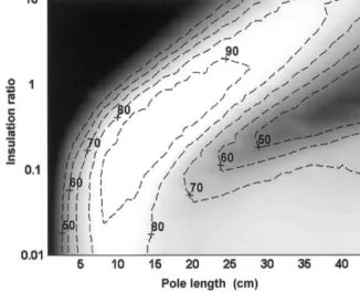
Figure 2 shows the dependence of system SNR on both antenna pole length and the amount of insulation used (insulation ratio ⫽ insulation thickness/antenna radius), as determined using the method-of-moments model. Sys-tem SNR was determined at a single point, 1.0 cm in the radial direction from the whip/coax junction. This radius is a nominal imaging distance for the antenna; system SNR at different radii can be approximated by multiplying this value by 1/r (with r expressed in cm). There is a strong dependence of SNR on both insulation thickness and an-tenna length. The white areas of the plot indicate high system SNR, while the black regions are areas of low system SNR.
For an antenna length of 8 cm, adding small amounts of insulation has little effect on system SNR. SNR remains relatively high until the insulation ratio exceeds 0.5. After this point, system SNR quickly drops. For longer antenna lengths, the allowable insulation thickness for high SNR increases. For example, a 16-cm pole should be insulated to a thickness ratio of 0.1–1.0. As was seen for the 8-cm antenna, adding too much insulation will dramatically reduce the system SNR. Overall, there are certain pairings of pole length and insulation thickness that will deliver high SNR (i.e., those that lie within the white region of the plot). Pairings outside this region— especially with exces-sive insulation thickness—will impair antenna perfor-mance.
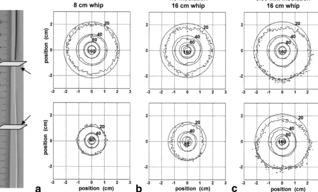
These simulation results were validated by comparing theoretical and empirical system SNR values for five loop-less antennas. Results from three antennas are shown in Fig. 3. For all antennas studied, the experimental and
FIG. 2. For high SNR performance, antenna length must be in-creased when insulation is added. Using the theoretical model of insulated loopless antennas, system SNR values were determined at a single point, 1.0 cm radially from the whip/coax junction. Values are reported as a percentage of the maximum system SNR ob-served (60000 mL–1Hz1/2), and show strong dependence on pole length and insulation ratio (insulation thickness/antenna radius). As the insulation ratio is increased, optimal pole length increases as well.
theoretical results show good agreement (empirical and theoretical results differed by⬍10%).
Helical Winding of Loopless Antennas
Figure 4 shows the dependence of system SNR on antenna pole length, winding pitch (turns/cm), and winding radius (determined using the method-of-moments model). Again, system SNR was determined at a single point, 1.0 cm in the radial direction from the whip/coax junction. White areas on the plot indicate high system SNR, while black areas show low SNR levels.
Similar to the case in Fig. 2, there are certain allowable combinations of winding pitch and antenna pole length for high SNR. In general, an increased winding pitch should be paired with a shorter pole length. Also note that the bigger the radius of winding, the larger the effect (i.e., the antenna can be shortened more, while preserving SNR performance). This should be contrasted with the effects of insulation, which allowed for high SNR performance with long whip lengths (Fig. 2). These two effects are comple-mentary and, depending on the intended use of the an-tenna, either insulation or winding, or both, may be used to modify the antenna dimensions and SNR profile.
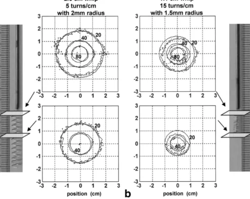
These simulation results were validated by comparing theoretical and empirical system SNR values for three loopless antennas. Results from two antennas are shown in Fig. 5. For all antennas studied, theoretical and empirical results differed by⬍20%.
Design and In Vivo Application of an IVES Imaging Antenna
Figure 6 shows system SNR profiles, experimentally mea-sured in a 20-L saline phantom, for the IVES loopless
antenna. With this design, approximately 20 cm of an-tenna length produces at least 80% of the maximum sys-tem SNR. Note that the majority of the useful region is actually over the coaxial shield of the antenna. Because of the heavy insulation, system SNR remains high for a long distance along the shield.
To demonstrate in vivo application, this antenna was advanced⬃40 cm into the abdominal aorta of a canine. For anatomical orientation, Fig. 7a shows a scout image ac-quired with a surface phased array. To confirm the posi-tioning of the imaging antenna, Fig. 7b shows a projection image acquired using the imaging antenna for both RF transmit and receive (image resolution and orientation is the same as in Fig. 7a). Then, without moving the imaging antenna, axial FSE images were acquired over a superior– inferior range of approximately 20 cm. Selected images are shown in Fig. 7c– e. To correct for the nonuniform sensi-tivity profile, these magnitude images were intensity-cor-rected by applying a 1/r weighting factor (where r is the distance from the antenna axis).
DISCUSSION
Insulation of Loopless Antennas
As has been demonstrated, insulation can have a very positive impact on the imaging performance of loopless antennas. Insulation broadens the length, along the axis of the antenna, over which SNR remains high. This effect can be explained by considering the resonant length of the insulated antenna (i.e., the pole length, approximately/4, that maximizes SNR). Wavelength is largely a function of the relative permittivity that surrounds the antenna ( ⫽
FIG. 3. Theoretical and experimental system SNR maps agree for insulated loopless antennas. a: Theoretical and experimental system SNR contours (103mL–1Hz1/2) in axial planes at the whip/coax junction and 5 cm down the whip for an uninsulated loopless antenna with an 8-cm whip. b: An uninsulated antenna with a 16-cm whip. c: A 16-cm antenna with 0.06 mm of insulation on the whip. Theoretical and experimental values differ by⬍10% in all cases.
1/(f 公ε) where f is the frequency of interest). In biological tissue, the relative permittivity is high and therefore the quarter wavelength at 64 MHz is short (on the order of 10 cm). However, when insulation with a low relative permittivity is added to the antenna, the “effective permit-tivity” seen by the antenna drops. This causes an increase in the quarter wavelength, and thus longer antennas be-come resonant. This causes a broadening of the current distribution on the antenna and, similarly, a broadening of the SNR distribution (Fig. 2). As shown in Fig. 7, this can be very advantageous in that several images can be col-lected along the lumen of a blood vessel without reposi-tioning the antenna.
Generally, MRI probes that have a large region of cover-age will have worse SNR performance than imaging probes with small coverage, because the former receive much more noise from the body. However, we have shown here that insulated loopless antennas maintain their SNR per-formance, even while the imageable coverage increases. This behavior is essentially equivalent to the effect of using distributed capacitance in MRI surface coils. Distrib-uted capacitance helps to lower the magnitude of “conser-vative” electric fields by reducing the magnitude of charge accumulation (22). This lowers dielectric losses and hence reduces noise resistance. For the loopless antenna, all of
the antenna capacitance exists between the two poles of the antenna, with the body and antenna insulation acting as the dielectric. With added insulation, the current profile on the antenna is broadened and thus charge density is decreased. This reduced charge density results in lower electric fields and less power deposition in the body, and hence a reduced contribution to noise resistance. At the same time, however, there is an increase in the amount of tissue wherein “magnetic losses” occur (i.e., the amount of tissue containing eddy currents (22)), because of the broad-ening of the current distribution. This effect will tend to raise noise resistance, offsetting the decrease due to the distributed capacitance effect. Considering both of these effects, there is little net change in SNR with the addition of antenna insulation (Fig. 2).
Insulation, if used properly, can significantly enhance the utility of loopless receivers. The most notable effect of insulation is the improved safety of the loopless antennas, which is a primary concern for any invasive device used with MRI. Insulation can significantly reduce the heating potential of linear wire structures in the MR environment (23). As seen here, insulation tends to increase the length at which an interventional wire becomes resonant (be-cause of the low relative permittivity of insulation com-pared to body tissue). For a fixed antenna length that is less
FIG. 4. Antenna winding allows the antenna whip to be shortened while high SNR performance is maintained. Using the theoretical model of helically wound loopless antennas, system SNR values were determined at a single point, 1.0 cm radially from the whip/coax junction. System SNR is plotted as a function of pole length and winding pitch for a winding radius of (a) 0.5 mm, (b) 0.75 mm, (c) 1.0 mm, and (d) 2.0 mm. Values shown are percentages of the maximum system SNR observed (50000 mL–1Hz1/2). System SNR shows less sensitivity to these parameters than is seen in Fig. 2.
than/2, this effect translates into reduced capacity to couple with the RF transmit field and reduced heating potential. This topic has been discussed in detail elsewhere (23). Helical Winding of Loopless Antennas
In general, the primary motivations to wind the loopless antenna whip will be to shorten the length of the antenna whip and improve mechanical stability. If it is left straight, the whip portion of the antenna can be very unstable, fragile, and long (especially when insulated). Antenna winding tends to improve the stability as well as the com-pliance of the whip, which is important for preventing vascular trauma when introducing the device (13).
The effect of winding on the imaging behavior of loop-less antennas can be considered complementary to that of insulation. While insulation tends to increase the pole length for best SNR performance, winding will reduce the
pole length. Most simply, the effect of antenna winding can be understood as compressing a long whip into a short physical dimension. With a small winding radius (Fig. 4a), there is less “wire packing,” and therefore the optimal pole length is not greatly affected by winding. However, with a large winding radius (Fig. 4d), packing is very efficient and the optimal pole length decreases dramatically with even a small amount of winding. While this roughly explains the effect of winding, the quantitative reduction in the an-tenna pole length is not nearly as dramatic as would be expected if this were the only factor. Winding also in-creases the self-inductance of the pole. Increased induc-tance will tend to sustain antenna currents and thus crease the quarter wavelength of the antenna. This in-crease in wavelength due to inductive effects partially offsets the reduction in pole length due to “wire packing,” resulting in the relationships shown in Fig. 4.
FIG. 5. Theoretical and experimental system SNR maps agree for helically wound loopless antennas. a: Theoretical and experimentally determined system SNR contours (103 mL–1Hz1/2) at the coax/whip junction (top panel) and 1 cm down the whip (bottom panel) for a 2.6-cm-long whip wound with 5 turns/cm and a radius of 2 mm. b: The same con-tours for a 1.1-cm-long whip wound with 15 turns/cm and a radius of 1.5 mm. Theoretical and experimental values dif-fer by⬍20% in all cases.
FIG. 6. Experimentally measured sys-tem SNR values for the IVES imaging antenna. System SNR is plotted as a function of distance, along the antenna axis, from the whip/coax junction for r⫽ 0.3, 0.5, 1.0, and 2.0 cm (where r is the radial distance from the antenna axis). The antenna is pictured below the SNR plot, and is properly aligned and scaled with the x-axis. Note that the majority of the useful area is over the coaxial shield, not the antenna whip.
In a previous work, it was suggested that winding of the antenna whip into a helical shape produces significant elliptical polarization of the antenna’s magnetic field (13). However, in the current work, there was little evidence of this elliptical polarization. Using the theoretical models, the full magnetic field distribution of the antennas can be solved. In all cases examined here, the field was predom-inantly linear. While elliptical polarization can be pro-duced for very short helical antennas (i.e., length ⬍⬍), this effect is largely absent for longer helical structures (24). In this case, the helical antenna behaves approxi-mately as a long, narrow solenoid. Outside the solenoid, magnetic fields produced by the circumferential compo-nent of the current cancel, leaving only the contribution from axially directed currents. Therefore, the magnetic field distribution is similar to that for a straight loopless antenna, which is linearly polarized.
Design and In Vivo Application of an IVES Imaging Antenna
For optimal system SNR, each pole of a loopless antenna should be approximately one-quarter wavelength long (8). In the context of an antenna that is both helically wound and insulated (i.e., the IVES imaging antenna), the goal is therefore to estimate what this quarter wavelength will be, given the combined effect of the insulation and winding. In the design example presented here (Figs. 6 and 7), we assume that the effects of insulation and winding are in-dependent and multiplicative. In other words, if enough
diameter of 1.1 mm was chosen for this antenna applica-tion (largely because this coax was readily available and familiar to us, and the diameter is acceptable for intravas-cular use). Heat-shrink insulation, with a recovered thick-ness of 0.6 mm, was added over the entire antenna. This yields an insulation ratio of⬃1 for the coaxial shield. As shown in Fig. 2, high SNR will be maintained for inserted coaxial shield lengths of 10 –30 cm, which covers the range of insertion depths needed (we measure the “length” of the coaxial shield pole as the distance from the antenna junc-tion to the body surface).
The whip was also covered with the same heat-shrink plastic. However, given that the whip radius is only 0.16 mm, the insulation ratio for the whip is 4. As indi-cated in Fig. 2, the whip length must be approximately 30 cm long for high SNR. This is an increase of approxi-mately 3.5 times over the uninsulated resonant length of 8.5 cm. Clearly, a whip length of this size would be unde-sirable (as the whip would extend far beyond the whip/ coax junction, where SNR is highest). However, winding can now be used to reduce the length of the whip to a manageable level. As shown in Fig. 4b, a pitch of 15 turns/cm and a winding radius of 0.75 turns/cm will reduce the optimal pole length from 8.5 to 3.5 cm. This is a reduction in pole length of approximately 2.5 times.
Therefore, by both insulating and winding the antenna, we expect the optimal pole length to be on the order of 12 cm (8.5 cm increased by 3.5 times due to the insulation effect, and then decreased by 2.5 times due to the winding effect). We chose a slightly smaller length (9 cm) in an effort to keep the whip length short. Because of the broad “allowable” regions shown in Figs. 2 and 4, this calcula-tion does not need to be exact for good antenna perfor-mance.
CONCLUSIONS
In this study we have demonstrated the design and use of an IVES imaging antenna. In the process, the effects of insulation and antenna winding on the SNR distribution of loopless antennas have been characterized and the overall understanding of loopless antenna behavior has been en-hanced. Loopless antennas should be thought of as dipole antennas, with one pole being formed by the whip and the other by the outer surface of the coaxial shield. For best SNR performance, these poles should be approximately one-quarter wavelength long. Insulation and antenna winding both affect the behavior of loopless antennas by
FIG. 7. Example of in vivo application of the IVES imaging antenna in a canine. a: An anatomical scout image acquired with a surface phased array. b: A projection image (i.e., an image acquired with no slice selection) using the imaging antenna for both RF transmit and receive. The imaging antenna, which is placed in the abdominal aorta, is seen to produce a broad longitudinal region of uniform signal. c– e: Selected axial FSE images, all acquired without moving the imaging antenna (FSE-xl, TR⫽ 1.4 s (2 ⫻ RR interval), TE ⫽ 5.7 ms, ETL⫽ 32, BW ⫽ 62.5 kHz, FOV ⫽ 10 cm, Thk ⫽ 3.0 mm, matrix⫽ 256 ⫻ 256, NEX ⫽ 4, scan time ⫽ 45 s). The image in panel
c was acquired on the whip 3 cm from the whip/coax junction, panel d was acquired at the whip/coax junction, and panel e was acquired
over the coax 6 cm from the whip/coax junction. Arrows indicate the position of the imaging antenna within the abdominal aorta.
altering this quarter wavelength. Insulation tends to in-crease the optimal pole length, while winding the antenna reduces it.
Furthermore, insulation can be used to reduce un-wanted device heating, improve biocompatibility, and in-crease the longitudinal coverage of loopless antennas (i.e., the region of the antenna with sufficient SNR for useful imaging). Similarly, subject to guidelines presented here, antenna winding can be used to increase the mechanical stability of the antenna and to shorten the required pole length while maintaining SNR performance.
ACKNOWLEDGMENTS
The authors thank Lawrence Hoffman and Glenn Mein-inger for assistance and consultation regarding the in vivo experiment, and Mary McAllister for editorial assistance. Robert Susil is supported by an NIH training grant.
REFERENCES
1. Haacke EM, Brown RW, Thompson MR, Venkatesan R. Magnetic reso-nance imaging—physical principles and sequence design. New York: Wiley-Liss; 1999. 914 p.
2. Kantor HL, Briggs RW, Balaban RS. In vivo 31P nuclear magnetic resonance measurements in canine heart using a catheter-coil. Circ Res 1984;55:261–266.
3. Hurst GC, Hua J, Duerk JL, Cohen AM. Intravascular (catheter) NMR receiver probe: preliminary design analysis and application to canine iliofemoral imaging. Magn Reson Med 1992;24:343–357.
4. Martin AJ, Plewes DB, Henkelman RM. MR imaging of blood vessels with an intravascular coil. J Magn Reson Imaging 1992;2:421– 429. 5. Balanis CA. Antenna theory. New York: John Wiley & Sons; 1997.
941 p.
6. Atalar E, Bottomley PA, Ocali O, Correia LC, Kelemen MD, Lima JA, Zerhouni EA. High resolution intravascular MRI and MRS by using a catheter receiver coil. Magn Reson Med 1996;36:596 – 605.
7. Quick HH, Ladd ME, Zimmermann-Paul GG, Erhart P, Hofmann E, von Schulthess GK, Debatin JF. Single-loop coil concepts for intravascular magnetic resonance imaging. Magn Reson Med 1999;41:751–758.
8. Ocali O, Atalar E. Intravascular magnetic resonance imaging using a loopless catheter antenna. Magn Reson Med 1997;37:112–118. 9. Serfaty JM, Yang X, Quick H, Aksit P, Atalar E. MRI-guided coronary
artery intervention. Circulation 2000;(suppl S)102:2480.
10. Serfaty JM, Yang X, Aksit P, Quick HH, Solaiyappan M, Atalar E. Toward MRI-guided coronary catheterization: visualization of guiding catheters, guidewires, and anatomy in real time. J Magn Reson Imaging 2000;12:590 –594.
11. Yang X, Atalar E. Intravascular MR imaging-guided balloon angioplasty with an MR imaging guide wire: feasibility study in rabbits. Radiology 2000;217:501–506.
12. Shunk KA, Garot J, Atalar E, Lima JA. Transesophageal magnetic res-onance imaging of the aortic arch and descending thoracic aorta in patients with aortic atherosclerosis. J Am Coll Cardiol 2001;37:2031– 2035.
13. Lardo AC, McVeigh ER, Halperin HR, Atalar E. A loopless helical intravascular MR imaging antenna. In: Proceedings of the 8th Annual Meeting of ISMRM, Denver, 2000. p 1312.
14. Edelstein WA, Glover GH, Hardy CJ, Redington RW. The intrinsic signal-to-noise ratio in NMR imaging. Magn Reson Med 1986;3:604 – 618.
15. Hoult DI. The principle of reciprocity in signal strength calculations—a mathematical guide. Concepts Magn Reson 2000;12:173–187. 16. Ocali O, Atalar E. Ultimate intrinsic signal-to-noise ratio in MRI. Magn
Reson Med 1998;39:462– 473.
17. Harrington RF. Field computation by moment methods. Dudley DG, editor. New York: IEEE Press; 1993. 229 p.
18. Atlamazoglou PE, Uzunoglu NK. A galerkin moment method for anal-ysis of an insulated antenna in a dissipative dielectric medium. IEEE Trans Microwave Theory Techniques 1998;46:988 –996.
19. Gardiol FE. Lossy transmission lines. Norwood, MA: Artech House; 1987. 384 p.
20. Henkelman RM. Measurement of signal intensities in the presence of noise in MR images. Med Phys 1985;12:232–233.
21. Stogryn A. Equations for calculating the dielectric constant of saline water. IEEE Trans Microwave Theory Technol 1971;MTT-19:733–736. 22. Chen CN, Hoult DI. Biomedical magnetic resonance technology. New
York: Bristol; 1989. 340 p.
23. Yeung CJ, Susil RC, Atalar E. RF safety of wires in interventional MRI: using a safety index. Magn Reson Med 2002;47:187–193.
24. Kraus JD. Antennas. Director SW, editor. New York: McGraw-Hill; 1988. 892 p.