Polymer
−Inorganic Core−Shell Nanofibers by Electrospinning and
Atomic Layer Deposition: Flexible Nylon
−ZnO Core−Shell Nanofiber
Mats and Their Photocatalytic Activity
Fatma Kayaci, Cagla Ozgit-Akgun, Inci Donmez, Necmi Biyikli,* and Tamer Uyar*
UNAM-Institute of Materials Science & Nanotechnology, Bilkent University, Ankara, 06800, Turkey
ABSTRACT: Polymer−inorganic core−shell nanofibers were produced by two-step approach; electrospinning and atomic layer deposition (ALD). First, nylon 6,6 (polymeric core) nanofibers were obtained by electrospinning, and then zinc oxide (ZnO) (inorganic shell) with precise thickness control was deposited onto electrospun nylon 6,6 nanofibers using ALD technique. The bead-free and uniform nylon 6,6 nanofibers having different average fiber diameters (∼80, ∼240 and ∼650 nm) were achieved by using two different solvent systems and polymer concentrations. ZnO layer about 90 nm, having uniform thickness around the fiber structure, was successfully deposited onto the nylon 6,6 nanofibers. Because of the low deposition temperature utilized (200 °C), ALD process did not deform the polymeric fiber structure, and highly conformal ZnO layer with precise thickness and composition over a large scale were accomplished regardless of the differences in fiber diameters. ZnO shell layer was found to have a polycrystalline nature with hexagonal wurtzite structure. The core−shell nylon 6,6-ZnO nanofiber mats were flexible because of the polymeric core component. Photocatalytic activity of the core−shell nylon 6,6-ZnO nanofiber mats were tested by following the photocatalytic decomposition of rhodamine-B dye. The nylon 6,6-ZnO nanofiber mat, having thinner fiber diameter, has shown better photocatalytic efficiency due to higher surface area of this sample. These nylon 6,6-ZnO nanofiber mats have also shown structural stability and kept their photocatalytic activity for the second cycle test. Ourfindings suggest that core−shell nylon 6,6-ZnO nanofiber mat can be a very good candidate as a filter material for water purification and organic waste treatment because of their photocatalytic properties along with structuralflexibility and stability.
KEYWORDS: electrospinning, ALD (atomic layer deposition), nanofibers, ZnO, core−shell, photocatalytic activity, nylon
■
INTRODUCTIONOne-dimensional (1D) nanostructures such as nanofibers have distinctive properties that can offer good opportunities for developing advanced materials and devices.1−3 Among the other nanofiber fabrication methods, electrospinning has gained growing interest in the past decade because this technique is quite versatile and cost-effective for producing functional nanofibers from variety of materials including polymers, polymer blends, emulsions, suspensions, sol−gels, metal oxides, composite structures as well as nonpolymeric systems, etc.2−8
Electrospun nanofibers and their nanofiber mats have
remarkable characteristics including a very high specific surface area, pore sizes within the nanoscale and very lightweight since thefiber diameter ranges from one micrometer down to a few tens of nanometers. Moreover, the control of thefiber surface morphology, fiber orientation, and cross-sectional
configura-tion, and designflexibility for physical/chemical modification is quite feasible for obtaining multifunctional electrospun nano-fibers. Because of their exceptional properties, it has been shown that these nanofibers/nanowebs have potentials for various applications in thefield of membranes/nanofilters,2−5,9 biomedical,2−5,10,11 nanocomposites,2−6,12 energy,2−5,13 sen-sor2−5and environment,2−5,13,14etc.
Polymer−inorganic composite nanofibrous structures have intriguing properties which combine the advantages of polymers such as structuralflexibility and lightweight with the properties of inorganic materials such as high mechanical strength, high thermal stability and excellent electrical, Received: August 27, 2012
Accepted: October 22, 2012
Published: October 22, 2012
magnetic, optical, catalytically properties, etc. These composite nanofibers have many potential applications in filtration,2,12,14 protective clothing,15 electronics,16 energy storage devices,17 sensors,18microwave absorbers,19etc. Morphological character-istics of the polymer−inorganic composite nanofibers are also very important for presenting their properties. For instance, core−shell nanofibers are quite attractive since their morphol-ogy could further enhance the material properties. Different methods such as radio frequency sputtering20 and metal− organic chemical vapor deposition,21etc. were utilized on the electrospun inorganic nanofibers to produce inorganic− inorganic core−shell nanofibers. Moreover, inorganic−inor-ganic coaxial nanofibers were also fabricated by coelectrospin-ning of two different sol−gel systems.22 On the other hand, polymer−polymer coaxial nanofibers have been extensively fabricated by using coaxial electrospinning setup23,24 or they can also be obtained by single spinneret electrospinning of blends of the two different types of polymers.25 Yet, the fabrication of polymer−inorganic core−shell nanofibers is somewhat challenging because the deposition of inorganic shell layer requires a high temperature process that can easily deform the polymeric core structure.
Recently, atomic layer deposition (ALD) technique has been explored to produce conformal and very thin inorganic coatings on fibrous systems such as cotton,26,27 cellulose-based filter paper,27−30nonwovens,26synthetic27,29and naturalfibers31and nanofibrillated cellulose32as well. ALD, which is a special type of low-temperature chemical vapor deposition, proceeds
though the sequential pulses of two or more precursors separated by purging/evacuation periods.33As the substrate is exposed to a certain precursor, gaseous precursor molecules saturate the surface by reacting with available surface sites, creating new sites for the following precursor. Film growth mechanism of ALD is inherently self-limiting, which gives rise to unique properties such as high uniformity and conformality, as well as subnanometer precise thickness control.33−35 ALD process providesflexibility so that very thin conformal layers of metals, metal oxides or metal nitrides can be coated onto different types of three-dimensional substrates.33−35 ALD was mostly studied on inorganic substrates, yet, recent studies showed that polymeric films36 and complex surfaces such as fibers and nonwovens26−32,36can also be coated by ALD. It has
also been shown that electrospun nanofibers can be used as a template for producing hollow nanofibers. For instance, Al2O3 microtubes with precise wall thickness control were fabricated by ALD of Al2O3onto electrospun poly(vinyl alcohol)fibers, in which the polymericfiber core was removed by calcination.37 Similarly, tubes or hollowfibers of various sizes and materials (Al2O3/ZnO/Al2O3multilayer,38TiO2,39CoFe2O4and Fe2O3 -particle doped TiO2,40ZnO,41,42SnO243) were synthesized by first depositing the inorganic shell by ALD and then removing the polymeric electrospun nanofiber templates by calcination. Moreover, the high surface area nanostructured Al2O3 tubes were also prepared by dissolution of ALD-coated electrospun PVAfibers without using calcination method.44ALD has also been utilized to coat and protect electrospun nylon-6
Figure 1.Schematic representations of the processing steps for the production of core−shell polymer-inorganic nanofibers: (a) electrospinning, (b) atomic layer deposition (ALD); (c) schematic representation of the formation process of core−shell polymer-inorganic nanofibers: preparation of the polymeric nanofiber by electrospinning and conformal inorganic shell deposition on the electrospun nanofiber via ALD.
nanofibers.45
The combination of ALD and electrospinning was also used to prepare TiO2-coated NiFe2O4-fibers40 and inorganic−inorganic core−shell nanofibers of TiO2−ZnO46 and SnO2−ZnO.47Nevertheless, to the best of our knowledge, the focus on the fabrication of polymer-inorganic core−shell nanofibers by combination of electrospinning and ALD has been very limited in the literature.45
Functional materials showing photocatalytic properties which facilitate the degradation of organic contaminants in water under visible or UV light has attracted significant interest in recent years.48−53Fibrous membranes made of nanofibers show remarkable photocatalytic properties due to their unique morphological features including high surface area and nanoporosity.48,49,52,53 ZnO is an important semiconductor material with a direct wide band gap (3.37 eV) and it is a well-known nontoxic catalyst and therefore, the potential application of ZnO for water purification has been investigated.48,49,51 Because the morphology of ZnO is quite crucial for photocatalytic efficiency, ZnO nanostructures in the form of nanoparticles and nanofibers have been examined in terms of their photocatalytic properties. It has been reported that ZnO nanoparticles and nanofibers have shown excellent photo-catalytic properties because of their very high surface area and more porous nature.48Nevertheless, the metal oxide nanofibers are quite brittle and do not show any structuralflexibility, and this cause significant problems during their handling and usage as a membrane material. For this reason, the development of flexible nanofibrous membranes or textiles having photo-catalytic properties is still on demand for self-cleaning and water purification and waste treatment.50,53
In this study, we have successfully achieved polymer-inorganic core−shell nanofibers by combining of electro-spinning and ALD processes; nylon 6,6 (polymeric core) nanofibers were obtained by electrospinning, and then, ZnO (inorganic shell) were precisely deposited onto electrospun nylon 6,6 nanofibers by ALD technique. Electrospun nylon 6,6 nanofibers having three different average diameters (∼80, ∼240 and∼650 nm) were coated with 90 nm of ZnO layer by ALD. Nylon 6,6 is a synthetic polymer type which is suitable for filtration application due to its distinctive properties such as high strength, toughness, elasticity, abrasion resistance and good chemical resistance. In addition, ZnO has unique properties due to its high photosensitivity, high catalytic activity, suitable band gap, low cost, and environmental compatibility,50,54as well as antibacterial property.49Here, we fabricatedflexible nylon 6,6-ZnO core−shell nanofibers having very high surface area, which have shown photocatalytic decomposition of rhodamine-B dye in aqueous solution. Our findings suggest that these nanofiber mats can be promising filtering materials for removal of organic pollutants for water cleaning or waste treatment.
■
RESULTS AND DISCUSSIONMorphology of the Electrospun Nylon 6,6 Nanofibers.
The two-step process for fabricating core−shell polymer-inorganic nanofibers via combination of electrospinning and ALD is illustrated in Figure 1. In the first step, nylon 6,6 nanofibers having three different average fiber diameters (AFD) were produced by electrospinning technique. Initially, solution properties (concentration and solvent type) were optimized for obtaining bead-free and uniform nanofibers from nylon 6,6. The characteristics (composition and viscosity) of the nylon 6,6 solutions and AFD of the electrospun nylon 6,6 nanofibers are summarized in Table 1. In electrospinning, fiber diameters strongly depend on the polymer solution viscosity, hence, type of the solvent used and concentration of the polymer solution are quite important to control the diameter of the electrospun fibers.4,55
Here, two different solvent systems were used; formic acid (FA) and hexafluoro-2-propanol (HFIP). 8% (w/v) nylon 6,6 was used for FA system while two different nylon 6,6 concentrations (5% and 8%, w/v) were used for HFIP system
in order to produce nanofibers with different AFD. The
viscosity of each nylon 6,6 solution was different; therefore, electrospinning of these solutions yielded nylon 6,6 nanofibers with different fiber diameter. It is anticipated that higher solution viscosity resulted in less stretching of the electrified jet and therefore thicker nanofibers were obtained in electro-spinning.4,55The representative SEM images of the electrospun nylon 6,6 nanofibers obtained from 8% (w/v) FA, and 5% and 8% (w/v) HFIP solutions are given in Figure 2(a1−3). It is apparent that uniform bead-free nanofibers having smooth surface were obtained in all three cases. AFD of the nylon 6,6 nanofibers was found as 80 ± 15, 240 ± 45, and 650 ± 140 nm for 8%-nylon 6,6/FA, 5%-nylon 6,6/HFIP and 8%-nylon 6,6/ HFIP systems, respectively. Although the polymer concen-tration of 8%-nylon 6,6/FA is higher than 5%-nylon 6,6/HFIP and same with 8%-nylon 6,6/HFIP, much thinner nanofibers (AFD = 80± 15 nm) were obtained because of the much lower solution viscosity of 8%-nylon 6,6/FA when compared to nylon 6,6/HFIP systems. These randomly oriented nylon 6,6
nanofibers having different AFD were used as the core
structures for fabrication of the core−shell nylon 6,6-ZnO nanofibers.
Morphology of the Core−Shell Nylon 6,6-ZnO
Nano-fibers. The next processing step is the deposition of ZnO shell on the electrospun nylon 6,6 nanofibers by ALD. ZnO shell was grown layer-by-layer onto the smooth and round surfaces of individual nylon 6,6 nanofibers by applying 800 ALD cycles at
200 °C. Figure 2 (b1−3) displays the representative SEM
images of the core−shell nylon 6,6-ZnO nanofibers having three different AFD. From these SEM images, it was clearly
observed that ALD process did not destroy the fibrous
structure of the electrospun nylon 6,6 samples, and uniform Table 1. Properties of Nylon 6,6 Solutions and the Resulting Electrospun Nanofibers
sample solvent
concentration of nylon 6,6 (% w/v)a
viscosity
(Pa·s) averagefiber diameter beforeALD (nm)
averagefiber diameter after
ALD (nm) fiber morphology 8%-nylon 6,6/FA NF FA 8 0.0228 80± 15 305± 50 bead-free nanofibers 5%-nylon 6,6/HFIP NF HFIP 5 0.115 240± 45 470± 70 bead-free nanofibers 8%-nylon 6,6/HFIP NF HFIP 8 0.24 650± 140 835± 320 bead-free nanofibers
thickness of ZnO deposition onto nylon 6,6 nanofibers was achieved successfully in all three cases.
As seen in Figure 2 (a1−3), nylon 6,6 nanofibers have
smooth and uniform surface, however, the surface of the core−
shell nylon 6,6-ZnO nanofibers was increased roughness
(Figure 2 (b1−3)) due to the grainy structure of the outer ZnO layer.56Since the deposited film is polycrystalline with a hexagonal wurtzite structure, ALD growth starts with the nucleation of ZnO islands. With the increasing number of ALD cycles, these islands coalesce to form a continuous film. The resulting film, therefore, consists of ZnO grains and this increase the surface roughness. Amorphousfilms deposited by ALD, on the other hand, generally result in smootherfilms with lower surface roughness values.57The SEM images also showed that the ALD process yielded uniform thickness of ZnO shell layer over a relatively large surface area of the electrospun nanofibers. In addition, no significant difference was observed for nylon 6,6 nanofibers having different AFD indicating that ZnO shell layer with uniform thickness can be deposited regardless of thefiber diameter variation. These results clearly
confirmed that ALD technique provided conformal ZnO
deposition onto electrospun nanofibers which is quite unique when compared to other less-conformal deposition methods such as sputtering.41The AFD of the core−shell nylon 6,6-ZnO nanofibers were measured as 305 ± 50, 470 ± 70, and 835 ± 320 nm for nylon 6,6/FA, 5%-nylon 6,6/HFIP and 8%-nylon 6,6/HFIP systems, respectively (Table 1). The AFD of nylon 6,6-ZnO nanofibers were more or less same with the
expected values when total of ∼180 nm thickness (∼90 nm
layer in both sides of thefiber) of ZnO layer was added to the fiber diameter of the nylon 6,6 core.
EDX analyses were also performed for the core−shell nylon 6,6-ZnO nanofibers. Zinc (Zn), oxygen (O) and carbon (C) elements were detected in the EDX spectrum (Figure 3); Zn
and O are originated from ZnO shell layer and C is coming from the polymeric core structure of nylon 6,6. Elemental
mapping results shown in Figure 3 further confirmed the
successful deposition of ZnO shell layer onto nylon 6,6 nanofibers.
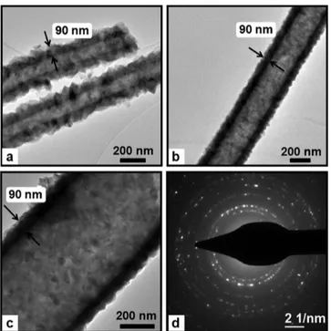
The morphologies of the core−shell nylon 6,6-ZnO
nanofibers were further investigated by TEM. The representa-tive TEM images given in Figure 4 clearly showed that nylon 6,6-ZnO nanofibers have core−shell structure. It is evident that ZnO shell layer with uniform thickness was deposited onto individual nylon 6,6 nanofibers. The surface of nylon 6,6-ZnO nanofibers was rougher due to the nanosize grains of ZnO having an average grain size of∼25 nm. The TEM images also revealed that the thickness of the ZnO shell layer was about 90 nm for each core−shell nylon 6,6-ZnO nanofiber sample having
different AFD (Figure 4). The conformal, layer-by-layer
deposition of ZnO onto the round surfaces of individual
electrospun nanofibers is unique to ALD process, which
resulted in uniform thickness of the ZnO shell layer even the nylon 6,6 nanofibers were randomly distributed in the form of nonwoven, and the fiber diameters were very different from
Figure 2.Representative SEM images of (a1) 8%-nylon 6,6/FA, (a2) 5%-nylon 6,6/HFIP, (a3) 8%-nylon 6,6/HFIP nanofibers; and (b1) nylon 6,6/FA-ZnO, (b2) 5%-nylon 6,6/HFIP-ZnO, (b3) 8%-nylon 6,6/HFIP-ZnO core−shell nanofibers. The insets show higher-magnification images.
Figure 3.EDX spectrum of nylon 6,6-ZnO core−shell nanofibers (8%-nylon 6,6/HFIP-ZnO NF) and chemical maps of C, Zn, and O.
each other. The representative SAED pattern of the core−shell nylon 6,6-ZnO nanofibers presented in Figure 4d indicates a polycrystalline nature of the ZnO shell, which correlates well with the XRD patterns of the nanofibers that will be discussed in the following sections.
Surface Analysis of the Core−Shell Nylon 6,6-ZnO
Nanofibers. Surface chemical composition and bonding states of the pristine nylon 6,6 nanofibers and core−shell nylon
6,6-ZnO nanofibers were investigated by using XPS. Table 2
summarizes the compositional data of pristine nylon 6,6 nanofibers and core−shell nylon 6,6-ZnO nanofibers in atomic concentrations. As anticipated, C 1s, O 1s, and N 1s peaks were detected in the XPS survey scan of pristine nylon 6,6 nanofibers since the nylon 6,6 polymer consists of carbon, oxygen and nitrogen atoms only. In the case of core−shell nylon 6,6-ZnO nanofibers, only Zn 2p3, O 1s and C 1s peaks were detected from survey scans. Zn and O contents were assigned to ZnO shell layers, which were found to be almost stoichiometric as expected. On the other hand, the absence of nitrogen peak in the XPS survey scans for core−shell nylon 6,6-ZnO nanofibers indicated that the surface of the nylon 6,6 nanofibers were coated successfully by ZnO layer using ALD. However, C was
observed for the core−shell nylon 6,6-ZnO nanofibers that was most probably due to surface contamination; because if the carbon content was from the polymer core, we would have also detected N for these nanofibers in the XPS scans. In order to prove this claim, we etched the ZnO shell by Ar ion sputtering for 30 s, and observed considerable decrease in the amount of C. Formation of ZnO on the surface of the nylon 6,6 nanofibers was also confirmed by Zn 2p high resolution XPS scan (Figure 5). Zn 2p3/2 and Zn 2p1/2 subpeaks of the Zn 2p doublet located at 1021.73 and 1044.76 eV, respectively, were found to be related to Zn−O bonding in ZnO.58
Thermal and Structural Analyses of the Core−Shell
Nylon 6,6-ZnO Nanofibers. We have also calculated the
compositional weight percentage of the core−shell nylon
6,6-ZnO nanofibers by TGA. The TGA thermograms (Figure 6)
indicated that 8%-nylon 6,6/FA-ZnO, 5%-nylon 6,6/HFIP-ZnO, and 8%-nylon 6,6/HFIP-ZnO contain 85, 81, and 80 weight% of ZnO, respectively and this approximately correlates with calculated theoretical weight% of ZnO in the core−shell fibers.
It was also noted that the main decomposition temperature of nylon 6,6 in core−shell nanofibers (decomposition onset at
about 270, 295, and 300 °C for 8%-nylon 6,6/FA-ZnO,
5%-nylon 6,6/HFIP-ZnO and 8%-5%-nylon 6,6/HFIP-ZnO, respec-tively) was lower than that of pristine nylon 66 nanofibers
Figure 4.Representative TEM images of (a) 8%-nylon 6,6/FA-ZnO, (b) 5%-nylon 6,6/HFIP-ZnO, (c) 8%-nylon 6,6/HFIP-ZnO core− shell nanofibers; (d) represantative SAED pattern of the core−shell nylon 6,6-ZnO nanofibers (8%-nylon 6,6/HFIP-ZnO NF).
Table 2. Atomic Concentrations Generated from XPS Wide Energy Survey Scans
samples C (%) O (%) Zn (%) N (%) pristine nylon 6,6 NF 76.52 12.5 10.93 8%-nylon 6,6/FA-ZnO NF 20 41.19 38.81 5%- nylon 6,6/HFIP-ZnO NF 18.45 44.36 37.19 8%-nylon 6,6/HFIP-ZnO NF 20.67 41.44 37.89 8%-nylon 6,6/FA-ZnO NF (after 1st
cycle of UV treatment)
27.05 41.07 31.88 8%-nylon 6,6/HFIP-ZnO NF (after
1st cycle of UV treatment)
23.39 43.38 32.63
Figure 5.Zn 2p high-resolution XPS scan of core−shell nylon 6,6-ZnO nanofibers (8%-nylon 6,6/FA-6,6-ZnO NF).
Figure 6.TGA thermograms of pristine nylon 6,6 and core−shell nylon 6,6-ZnO nanofibers.
(decomposition onset at 350°C) which is possibly due to the catalytic activity of ZnO resulting in oxidative and earlier decomposition of nylon 6,6. A similar result was reported where the thermal degradation temperature of polymer was decreased with the presence of TiO2as inorganicfiller.59
We also performed ATR-FTIR analysis (data not given) to see if there is any degradation of nylon 6,6 during the ALD process. Amide I and amide II peaks of pristine nylon 6,6
nanofibers were observed at around 1635 cm−1 (CO
stretch)60 and 1539 cm−1 (in-plane N−H deformation),60 respectively. We did not see any significant change in these
characteristic FTIR peaks for core−shell nylon 6,6-ZnO
nanofibers when compared to pristine nylon 6,6 nanofibers, suggesting that there was no degradation of nylon 6,6 nanofibers during or after the ALD process.
The XRD patterns of pristine nylon 6,6 and core−shell nylon 6,6-ZnO nanofibers are given in Figure 7. Nylon 6,6 has various
crystalline forms calledα phase, β phase, and γ phase.61 The XRD pattern of the pristine nylon 6,6 nanofibers exhibited two distinct diffraction peaks at about 20.4° (100) and 23.0° (010, 110) confirming the presence of the α phase in the sample.61,62 Theα1 peak (2θ = 20.4°) corresponds to the distance between
hydrogen-bonded chains, whereas the α2 peak (2θ = 23°)
corresponds to the separation of hydrogen-bonded sheets.61 The absence of the reflections of β phase at 2θ values of ∼12 and 19° or γ1 peak (2θ = 13°) and γ2 peak (2θ = 22°)61in the XRD pattern of pristine nylon 6,6 nanofibers indicates that the nylon 6,6 nanofibers have a pure triclinic α phase comprising hydrogen-bonded sheets.63 The XRD patterns of nylon 6,6 nanofibers obtained from FA and HFIP solvent systems were
the same, indicating thatα crystalline phase was obtained from both solvent systems.
In the case of core−shell nylon 6,6-ZnO nanofibers, the XRD patterns of all three samples have shown the diffraction peaks of the hexagonal wurtzite crystal structure of ZnO (ICDD 01− 074−0040) elucidating the successful deposition of ZnO onto electrospun nylon 6,6 nanofibers by ALD. Although the nylon 6,6 diffraction peak intensities were substantially decreased due to the presence of ZnO layer, the peaks of nylon 6,6 ofα1 and α2 phase were also observed in the XRD patterns of core−shell
nylon 6,6-ZnO nanofibers. This also suggested that the
crystalline structure of nylon 6,6 nanofibers was not affected during the ALD process.
Photocatalytic Activity of the Core−Shell Nylon
6,6-ZnO Nanowebs. Here, we demonstrate that the core−shell
nylon 6,6-ZnO nanofiber mat can be a very good candidate as filtering material because of the flexible polymeric core and the photocatalytic activity of the ZnO shell layer. These nanofiber mats can be easily handled and folded as a free-standing material (Figure 8c). We have tested the photocatalytic activity of the core−shell nylon 6,6-ZnO nanofiber mats by following
the photocatalytic decomposition of rhodamine-B (Rh−B)
which was used as a model azo-reactive dye under the irradiation of UV-light at 365 nm wavelength. The core−shell nylon 6,6-ZnO nanofibers having two different AFD (8%-nylon
6,6/FA, AFD ∼80 nm and 8%-nylon 6,6/HFIP, AFD ∼650
nm) were used in order to investigate the effect of fiber diameter on the efficiency of photocatalytic activity. The photocatalytic activity of these core−shell nylon 6,6-ZnO
nanofiber mats were studied by spectroscopic UV−vis
measurement, by recording the change in the absorbance of the Rh−B solutions as a function of the UV irradiation time. As a control experiment, the Rh−B solution without containing any nanofibers was subjected to the same UV treatment in order to investigate whether any direct photolysis occurred or not. The change in the absorption peak of Rh−B at 554 nm in
the UV−Vis spectra was monitored as a function of UV
irradiation time (Figure 8a). Moreover, the absorption peak points were used for calculating the degradation rate of Rh−B
defined as C/C0 where C0 and C represent the initial
concentration of Rh−B before UV irradiation and after UV irradiation at time t, respectively (Figure 8b). As given in Figure 8a, direct photolysis was not observed for the blank Rh−B solution without containing core−shell nylon 6,6-ZnO nano-fiber mat, and therefore the pink color of the Rh−B solution was not changed after the UV irradiation over a period of 16 h. On the other hand, the reduction of the absorbance of the Rh− B solutions containing core−shell nylon 6,6-ZnO nanofiber mats with respect to UV irradiation time clearly showed effective photocatalytic degradation of Rh−B. Furthermore, the photocatalytic degradation rate of Rh−B was higher for
8%-nylon 6,6/FA (AFD∼80 nm) nanofiber mat compared to
8%-nylon 6,6/HFIP (AFD ∼650 nm) nanofiber mat, which was
possibly due to the much thinnerfiber diameter and resulting higher surface area of this sample. For 8%-nylon 6,6/FA nanofiber mat, 59% of Rh−B decomposed in 4 h and total of 93% of Rh−B was decomposed in 16 h. In the case of 8%-nylon 6,6/HFIP nanofiber mat, the decomposition of Rh−B was 47% and 88% in 4 and 16 h, respectively. The Rh−B solutions containing nylon 6,6-ZnO nanofiber mats were decolorized during the UV irradiation and pink color of these solutions was almost disappeared after 16 h of UV irradiation elucidating the
Figure 7.XRD patterns of pristine nylon 6,6 and core−shell nylon 6,6-ZnO nanofibers.
successful photocatalytic decomposition of Rh−B by the core− shell nylon 6,6-ZnO nanofiber mats (Figure 8a).
The structural stability of these core−shell nylon 6,6-ZnO
nanofiber mats is quite important because the potential
application of these nanofibrous membranes would be in
water purification where continuous and long lasting photo-catalytic activity is required for the treatment of organic pollutants present in the water supply. Accordingly, we have also examined the stability of these core−shell nylon 6,6-ZnO nanofiber mats. The structural and chemical stabilities of these
nylon 6,6-ZnO nanofiber mats were investigated by SEM
imaging and XPS measurement after the UV irradiation experiment. Figure 9 shows the representative SEM images of the 8%-nylon 6,6/FA and 8%-nylon 6,6/HFIP nanofiber mats after 16 h of UV irradiation in Rh−B solution. It was observed that the samples maintained their nanofibrous structure without any deformation; yet, in a few spots, destruction of ZnO layer
was detected. This is possible because of the mechanical
deformation of the nanofiber mat during the UV−vis
measurements where the nanofiber mats were pressed in the bottom of the UV cuvettes. Therefore, the ZnO shell layer was damaged to some extent but not significantly. The XPS study of these samples after the UV irradiation experiment also revealed the loss of a small amount of ZnO layer from the samples (Table 2).
We repeated the photocatalytic activity experiment for these nylon 6,6-ZnO nanofiber mats in order to investigate the potential reusability of these materials for the photocatalytic decomposition of Rh−B solution. The photocatalytic efficiency of these nanofiber mats for the second cycle was slightly lower than thefirst cycle. Therefore, in the second cycle, 85 and 80% of the Rh−B was decomposed in 16 h for 8%-nylon 6,6/FA and 8%-nylon 6,6/HFIP nanofiber mats, respectively. This slight decrease is possibly due to the loss of some ZnO layer after the first cycle; in addition, in the second cycle, a smaller amount of material was used for the photocatalytic activity experiment (9.3 mg of nanofiber mats was used in the first cycle and 8.7 mg of nanofiber mats was used in the second cycle, because some amount of nanofiber mat was used in SEM and XPS analyses after the first cycle). Furthermore, we observed that the nanofibers maintained their flexibility after second cycle of UV treatment as shown in Figure 8c. From the ATR-FTIR analysis (data not shown) of these samples after second cycle of UV treatment, we did not detect any notable change in the characteristic IR peaks of nylon 6,6 nanofibers (amide I and amide II peaks) when compared to pristine nylon 6,6 nanofibers, and this suggested that the photocatalytic activity of ZnO layer did not cause any significant degradation of polymeric core.
Figure 8.(a) UV−vis spectra of the Rh−B solution with and without core−shell nylon 6,6-ZnO nanofibers as a function of the UV irradiation time for 1st cycle experiment, (b) the rate (C/C0) of Rh−B degradation of the Rh−B solution with and without core−shell nylon 6,6-ZnO nanofibers by
exposing UV light with 365 nm wavelength for 1st and 2nd cycle experiments; (c) representative photographs of theflexible nylon 6,6-ZnO core− shell nanofibers before UV treatment and after 2nd cycle of UV treatment.
Figure 9.Representative SEM images of (a) 8%-nylon 6,6/FA-ZnO and (b) 8%-nylon 6,6/HFIP-ZnO core−shell nanofibers after 16 h of UV irradiation in Rh−B solution (1st cycle).
■
CONCLUSIONSIn this study, we have fabricated of core−shell nylon 6,6-ZnO nanofibers by combining electrospinning and ALD techniques. In thefirst step, nylon 6,6 nanofibers having different average fiber diameters were electrospun by using different solvent systems. In the second step, ZnO shell layer with precise thickness was deposited on the round surface of the nylon 6,6
nanofibers by ALD. The imaging analyses by SEM and TEM
revealed the core−shell structure of nylon 6,6-ZnO nanofibers, and the thickness of the ZnO shell layer was measured∼90 nm for each sample having different core fiber diameters. ALD provided growth of ZnO layer having uniform thickness regardless of the differences in core fiber diameter. In addition, it was observed that the nylon 6,6 fibrous structure was not deformed during the ALD of ZnO shell layer. This confirms that ALD has significant advantages over other deposition techniques such as less-conformal sputtering and high-temper-ature conventional CVD, since ALD is a relatively low temperature process where the thermal damage can be avoided when temperature-sensitive substrates such as polymers are used.
The core−shell nylon 6,6-ZnO nanofibers have shown
unique properties such as structural flexibility due to the polymeric core and photocatalytic activity due to the ZnO shell layer. The photocatalytic properties of the core−shell nylon
6,6-ZnO nanofiber mats were tested by monitoring the
photocatalytic decomposition of rhodamine-B organic dye molecule, which was used as a model organic waste compound. We observed that nylon 6,6-ZnO nanofiber mat having thinner
average fiber diameter (AFD ∼80 nm) has shown better
photocatalytic efficiency when compared to the nanofiber mat having AFD of ∼650 nm, possibly due to the higher surface area of this sample. We have also shown that these nylon 6,6-ZnO nanofiber mats are chemically and structurally stable after the second cycle of the photocatalytic experiments carried out under UV irradiation.
In brief, our results indicate that core−shell nylon 6,6-ZnO nanofiber mats can be quite applicable as a filtering/membrane material for treatment of organic pollutants for water purification due to their efficient photocatalytic properties, structuralflexibility and stability. Nevertheless, the combination of electrospinning and ALD techniques offers a promising alternative approach for the fabrication of functional core−shell nanofiber structures. ALD is a relatively low-temperature process providing ultimate conformality, therefore, three-dimensional, polymeric nanofiber templates can easily be coated by ALD of inorganic materials for producing flexible nanofiber mats. Consequently, depending on the type of the polymeric core and the type of the shell layer, various polymer−inorganic core−shell nanofibers can be fabricated for many applications including filters/membranes, catalysis, sensors, photonics, electronics, energy, biotechnology, etc.
■
MATERIALS AND METHODSMaterials. Nylon 6,6 pellets (relative viscosity: 230.000−280.000) were purchased from Sigma-Aldrich. Formic acid (FA, Sigma-Aldrich, 98−100%), 1,1,1,3,3,3-hexafluoro-2-propanol (HFIP, Sigma-Aldrich, ≥ 99%) and rhodamine-B (Rh−B, Sigma-Aldrich, dye content ∼95%) were used in this study. In addition, diethyl zinc ((C2H5)2Zn,
Sigma-Aldrich) and HPLC grade water (H2O) were used as the zinc
precursor and oxidant for the ALD of ZnO, respectively. All materials were used without any purification.
Electrospinning of Nylon 6,6 Nanofibers. Electrospinning of nylon 6,6 nanofibers having different average fiber diameters were obtained by varying the solvent type. Accordingly, 8 wt % nylon 6,6 was dissolved in the as-received two different solvents; HFIP and FA, separately; and 5 wt % nylon 6,6 was dissolved in HFIP as well. These solutions were stirred for 3 h at room temperature. The homogeneous clear solutions were placed in 3 mL syringes fitted with metallic needles of 0.8 mm of inner diameter. Then the syringes werefixed horizontally on the syringe pump (model SP 101IZ, WPI). The polymer solutions were pumped with feed rate of 1 mL/h during electrospinning. The applied voltage to the metal needle tip by using high voltage power supply (Matsusada, AU Series) was 15 kV and the tip-to-collector distance was set at 10 cm for the electrospinning of the prepared solutions. On the way to the grounded stationary cylindrical metal collector (height: 15 cm, diameter: 9 cm), the solvents evaporated and the electrospun nylon 6,6 nanofibers were deposited on the aluminum foil covering on the collector. The electrospinning processes were carried out at 23°C and 36% relative humidity in an enclosed Plexiglas box.
Preparation of ZnO Shell Structure by ALD. ZnO deposition on the electrospun nylon 6,6 nanofibers was carried out at 200 °C in a Savannah S100 ALD reactor (Cambridge Nanotech). Deposition rate of ZnO on the nylon 6,6 nanofibers at this temperature was ∼1.13 Å/ cycle. N2was used as the carrier gas with aflow rate of 20 sccm. 800
cycles were deposited, where one cycle consisted of diethyl zinc pulse (0.015 s)/ N2purge (10 s)/ H2O pulse (0.015 s)/N2purge (10 s).
This yielded about 90 nm of uniform ZnO coating onto nylon 6,6 nanofibers, which is satisfactory to achieve core−shell nanofibers having different core fiber diameter (∼80, ∼240 and ∼650 nm).
Characterization Techniques. The viscosity of the nylon 6,6 solutions was measured by using Anton Paar Physica MCR-301 Rheometer equipped with a cone/plate accessory using the spindle type CP40−2 at 22 °C and a constant shear rate of 100 s−1. The
morphology, uniformity and dimensions of the pristine nylon 6,6 nanofibers and core−shell nylon 6,6-ZnO nanofibrous membranes were studied by using scanning electron microscope (SEM) (FEI− Quanta 200 FEG). The samples were coated with 5 nm Au/Pd prior to SEM imaging. In order to determine the averagefiber diameter (AFD) from SEM images, around 100 fibers were analyzed. The elemental analyses of the core−shell nylon 6,6-ZnO nanofibers without coating of Au/Pd were performed by using SEM equipped with an energy dispersive X-ray (EDX) system operating at an accelerating voltage of 15 kV. Additionally, transmission electron microscope (TEM) (FEI− Tecnai G2F30) was used for the detailed morphological investigation of the core−shell nylon 6,6-ZnO nanofibers, as well as measurement of core and shell thicknesses. For TEM image, the samples were prepared by sonicating core−shell nylon 6,6-ZnO nanofibers in ethanol for 5 min and dropping the suspensions onto the HC200 TEM grids, and allowing them to dry under IR lamp for few minutes. Selected area electron diffraction (SAED) patterns of the core−shell nylon 6,6-ZnO nanofibers were also obtained by using TEM in order to investigate the crystal structure of ZnO shell. The surface compositions of pristine nylon 6,6 nanofibers and the core−shell nylon 6,6-ZnO nanofibers were determined by using X-ray photoelectron spectroscopy (XPS, Thermo Scientific) by means of a flood gun charge neutralizer system equipped with a monochromated Al KαX-ray source (hν = 1486.6 eV). XPS
data were taken from 400μm diameter circular spot on the surface of the samples. Wide energy survey scans (WESSs) were obtained over a 0−1360 eV binding energy (BE) range, at pass energy of 150 eV, and with an energy step of 1 eV. The high-resolution spectra were recorded for Zn 2p regions at pass energy of 30 eV, and with energy steps of 0.1 eV in order to analyze the bonding states. The thermal analysis of the nanofibers by thermal gravimetric analyzer (TGA) (TA Q500) was performed from room temperature to 550 °C with a heating rate of 20°C/min under the nitrogen atmosphere. Moreover, X-ray diffraction (XRD) data of the pristine nylon 6,6 nanofibers and core−shell nylon 6,6-ZnO nanofibrous membranes were collected within the range of 2θ = 10−100° by using PANalytical X’Pert Multi-Purpose X-ray Diffractometer with Cu Kα radiation, operating at a
voltage of 45 kV and a current of 40 mA. The structures of the nanofibers were investigated by attenuated total reflectance Fourier transform infrared spectroscopy (ATR-FTIR) (Bruker, VERTEX 70) The ATR-FTIR spectra were recorded from 700 to 4000 cm−1with a resolution of 4 cm−1by taking 64 scans for each sample, and these spectra were obtained with FTIR spectrometer equipped with a liquid nitrogen cooled mercury cadmium telluride (MCT) detector by using ATR set up containing a germanium crystal.
Photocatalytic Activity of the Core−Shell Nylon 6,6-ZnO Nanofibrous Membranes. The photocatalytic activity of the samples was analyzed by the photodegradation of rhodamine-B (Rh−B) (1.04 × 10⁻⁵ M) in aqueous medium. 8%-nylon 6,6/FA-ZnO and 8%-nylon 6,6/HFIP-6,6/FA-ZnO were used in this experiment in order to investigate the effect of fiber diameter on the photocatalytic activity. The core−shell nylon 6,6 - ZnO nanofibrous membranes (weight of nanofiber mat: 9.3 mg, thickness of the nanofiber mats: ∼70 μm, weight of nanofiber mats: 2.0 × 1.5 cm2(8%-nylon 6,6/FA NF)
and 2.0× 2.0 cm2 (8%-nylon 6,6/HFIP NF)) was put into quartz
cuvettes (width: 1 cm, length: 1 cm, and height: 5 cm, Hellma)filled with Rh−B solution (3.0 mL). The cuvettes were placed with a distance of 10 cm from the UV source (8 W, UVLMS-38 EL) and kept under UV irradiation at 365 nm wavelength. Dye concentration in the cuvettes was measured by using UV−vis−NIR spectrophotometer (Varian Cary 5000) at certain time intervals. The core−shell nylon 6,6-ZnO nanofibrous membranes stayed at the bottom of the dye solution during the experiment, and therefore the membranes did not interfere with the UV−vis measurement.
■
AUTHOR INFORMATIONCorresponding Author
*E-mail: [email protected] (N.B.); tamer@unam. bilkent.edu.tr (T.U.). +90 3122903556 (N.B.); +90 3122903571 (T.U.). +90 312 2664365 (N.B.); +90 3122664365 (T.U.).
Notes
The authors declare no competingfinancial interest.
■
ACKNOWLEDGMENTSState Planning Organization (DPT) of Turkey is acknowledged for the support of UNAM-Institute of Materials Science and Nanotechnology. T.U. and N.B. acknowledge Marie Curie International Reintegration Grant (IRG) for funding NANO-WEB (PIRG06-GA-2009-256428) and NEMSmart (PIRG05-GA-2009-249196) projects, respectively. F.K. and C.O. acknowledge TUBITAK-BIDEB for National PhD Scholarship. Authors also acknowledge M. Guler from UNAM for TEM analyses.
■
REFERENCES(1) Xia, Y.; Yang, P.; Sun, Y.; Wu, Y.; Mayers, B.; Gates, B.; Yin, Y.; Kim, F.; Yan, H. Adv. Mater. 2003, 15, 353.
(2) Lu, X.; Wang, C.; Wei, Y. Small 2009, 5, 2349.
(3) Ramakrishna, S.; Jose, R.; Archana, P.; Nair, A.; Balamurugan, R.; Venugopal, J.; Teo, W. J. Mater. Sci. 2010, 45, 6283.
(4) Ramakrishna, S. An Introduction to Electrospinning and Nanofibers; World Scientific: Singapore, 2005.
(5) Greiner, A.; Wendorff, J. Angew. Chem. Int.Edit. 2007, 46, 5670. (6) Teo, W. E.; Ramakrishna, S. Compos. Sci. Technol. 2009, 69, 1804. (7) Agarwal, S.; Greiner, A. Polym. Adv. Technol. 2011, 22, 372. (8) Celebioglu, A.; Uyar, T. Nanoscale 2012, 4, 621.
(9) Uyar, T.; Havelund, R.; Hacaloglu, J.; Besenbacher, F.; Kingshott, P. ACS Nano 2010, 4, 5121.
(10) Agarwal, S.; Greiner, A.; Wendorff, J. H. Adv. Funct. Mater. 2009, 19, 2863.
(11) Xie, J.; Li, X.; Xia, Y. Macromol. Rapid Commun. 2008, 29, 1775. (12) Rahul, R.; Kumar, S.; Sridhar, R.; Sundaramurthy, J.; Reddy, V. J.; Ramakrishna, S. J. Mater. Chem. 2012, 22, 12953.
(13) Thavasi, V.; Singh, G.; Ramakrishna, S. Energy Environ. Sci. 2008, 1, 205.
(14) Yoon, K.; Hsiao, B. S.; Chu, B. J. Mater. Chem. 2008, 18, 5326. (15) Roso, M.; Sundarrajan, S.; Pliszka, D.; Ramakrishna, S.; Modesti, M. Nanotechnology 2008, 19, 285707.
(16) Vacca, P.; Nenna, G.; Miscioscia, R.; Palumbo, D.; Minarini, C.; Sala, D. D. J. Phys. Chem. C 2009, 113, 5777.
(17) Kim, P.; Doss, N. M.; Tillotson, J. P.; Hotchkiss, P. J.; Pan, M. J.; Marder, S. R.; Li, J.; Calame, J. P.; Perry, J. W. ACS Nano 2009, 3, 2581.
(18) Lu, P. P.; Xu, Z.-L.; Yang, H.; Wei, Y. M. ACS Appl. Mater. Interfaces 2012, 4, 1716.
(19) Zhu, J.; Wei, S.; Chen, X.; Karki, A. B.; Rutman, D.; Young, D. P.; Guo, Z. J. Phys. Chem. C 2010, 114, 8844.
(20) Liu, L.; Zhang, H.; Wang, Y.; Su, Y.; Ma, Z.; Xie, Y.; Zhao, H.; Chen, C.; Liu, Y.; Guo, X. Nanoscale Res. Lett. 2010, 5, 1418.
(21) Fragalà, M.; Cacciotti, I.; Aleeva, Y.; Nigro, R. L.; Bianco, A.; Malandrino, G.; Spinella, C.; Pezzotti, G.; Gusmano, G. CrystEng-Comm. 2010, 12, 3858.
(22) Zhou, X.; Shang, C.; Gu, L.; Dong, S.; Chen, X.; Han, P.; Li, L.; Yao, J.; Liu, Z.; Xu, H. ACS Appl. Mater. Interfaces 2011, 3, 3058.
(23) Sun, Z.; Zussman, E.; Yarin, A. L.; Wendorff, J. H.; Greiner, A. Adv. Mater. 2003, 15, 1929.
(24) Zhang, Y.; Huang, Z. M.; Xu, X.; Lim, C. T.; Ramakrishna, S. Chem. Mater. 2004, 16, 3406.
(25) Chen, M.; Dong, M.; Havelund, R.; Regina, V. R.; Meyer, R. L.; Besenbacher, F.; Kingshott, P. Chem. Mater. 2010, 22, 4214.
(26) Hyde, G. K.; Scarel, G.; Spagnola, J. C.; Peng, Q.; Lee, K.; Gong, B.; Roberts, K. G.; Roth, K. M.; Hanson, C. A.; Devine, C. K. Langmuir 2009, 26, 2550.
(27) Jur, J. S.; Sweet, W. J., III; Oldham, C. J.; Parsons, G. N. Adv. Funct. Mater. 2011, 21, 1993.
(28) Hyde, G.; McCullen, S.; Jeon, S.; Stewart, S.; Jeon, H.; Loboa, E.; Parsons, G. Biomed. Mater. 2009, 4, 025001.
(29) Jur, J. S.; Spagnola, J. C.; Lee, K.; Gong, B.; Peng, Q.; Parsons, G. N. Langmuir 2010, 26, 8239.
(30) Kemell, M.; Pore, V.; Ritala, M.; Leskelä, M.; Lindén, M. J. Am. Chem. Soc. 2005, 127, 14178.
(31) Hyde, G. K.; Park, K. J.; Stewart, S. M.; Hinestroza, J. P.; Parsons, G. N. Langmuir 2007, 23, 9844.
(32) Korhonen, J. T.; Hiekkataipale, P.; Malm, J.; Karppinen, M.; Ikkala, O.; Ras, R. H. A. ACS Nano 2011, 5, 1967.
(33) Leskelä, M.; Ritala, M. Angew. Chem., Int. Ed. 2003, 42, 5548. (34) George, S. M. Chem. Rev. 2010, 110, 111.
(35) Detavernier, C.; Dendooven, J.; Sree, S. P.; Ludwig, K. F.; Martens, J. A. Chem. Soc. Rev. 2011, 40, 5242.
(36) Gong, B.; Parsons, G. N. J.Mater.Chem. 2012, 22, 15672. (37) Peng, Q.; Sun, X. Y.; Spagnola, J. C.; Hyde, G. K.; Spontak, R. J.; Parsons, G. N. Nano Lett. 2007, 7, 719.
(38) Peng, Q.; Sun, X. Y.; Spagnola, J. C.; Saquing, C.; Khan, S. A.; Spontak, R. J.; Parsons, G. N. ACS Nano 2009, 3, 546.
(39) Kim, G. M.; Lee, S. M.; Michler, G.; Roggendorf, H.; Gosele, U.; Knez, M. Chem. Mater. 2008, 20, 3085.
(40) Santala, E.; Kemell, M.; Leskelä, M.; Ritala, M. Nanotechnology 2009, 20, 035602.
(41) Park, J. Y.; Choi, S. W.; Kim, S. S. Nanotechnology 2010, 21, 475601.
(42) Cho, S.; Kim, D. H.; Lee, B. S.; Jung, J.; Yu, W. R.; Hong, S. H.; Lee, S. Sens. Actuators-B 2012, 162, 300.
(43) Lee, B. S.; Kim, W. S.; Kim, D. H.; Kim, H. C.; Hong, S. H.; Yu, W. R. Smart Mater. Struct. 2011, 20, 105019.
(44) Heikkilä, P.; Hirvikorpi, T.; Hilden, H.; Sievänen, J.; Hyvärinen, L.; Harlin, A.; Vähä-Nissi, M. J. Mater. Sci. 2012, 47, 3607.
(45) Oldham, C. J.; Gong, B.; Spagnola, J. C.; Jur, J. S.; Senecal, K. J.; Godfrey, T. A.; Parsons, G. N. J. Electrochem. Soc. 2011, 158, D549.
(46) Park, J. Y.; Choi, S. W.; Lee, J. W.; Lee, C.; Kim, S. S. J. Am. Ceram. Soc. 2009, 92, 2551.
(47) Choi, S. W.; Park, J. Y.; Kim, S. S. Nanotechnology 2009, 20, 4656034.
(48) Liu, H.; Yang, J.; Liang, J.; Huang, Y.; Tang, C. J. Am. Ceram. Soc. 2008, 91, 1287.
(49) Vitchuli, N.; Shi, Q.; Nowak, J.; Kay, K.; Caldwell, J. M.; Breidt, F.; Bourham, M.; McCord, M.; Zhang, X. Sci. Technol. Adv. Mater. 2011, 12, 055004.
(50) Bedford, N.; Steckl, A. ACS Appl. Mater. Interfaces 2010, 2, 2448. (51) Sugunan, A.; Guduru, V. K.; Uheida, A.; Toprak, M. S.; Muhammed, M. R. J. Am. Ceram. Soc. 2010, 93, 3740.
(52) Choi, S. K.; Kim, S.; Lim, S. K.; Park, H. J. Phys. Chem. C 2010, 114, 16475.
(53) Zhao, T.; Liu, Z.; Nakata, K.; Nishimoto, S.; Murakami, T.; Zhao, Y.; Jiang, L.; Fujishima, A. J. Mater. Chem. 2010, 20, 5095.
(54) Zhu, C.; Lu, B.; Su, Q.; Xie, E.; Lan, W. Nanoscale 2012, 4, 3060. (55) Uyar, T.; Besenbacher, F. Polymer 2008, 49, 5336.
(56) Zhang, Z.; Li, X.; Wang, C.; Wei, L.; Liu, Y.; Shao, C. J. Phys. Chem. C 2009, 113, 19397.
(57) Elam, J.; Sechrist, Z.; George, S. Thin Solid Films 2002, 414, 43. (58) Pan, K. Y.; Lin, Y. H.; Lee, P. S.; Wu, J. M.; Shih, H. C. J. Nanomater. 2012, 2012, 279245.
(59) Li, W.; Li, H.; Zhang, Y. M. J. Mater. Sci. 2009, 44, 2977. (60) Shi, J.; Wang, Y.; Gao, Y.; Bai, H. Compos. Sci. Technol. 2008, 68, 1338.
(61) Li, J.; Zuo, Y.; Cheng, X.; Yang, W.; Wang, H.; Li, Y. J. Mater. Sci.: Mater. Med. 2009, 20, 1031.
(62) Leo, C.; Linggawati, A.; Mohammad, A.; Ghazali, Z. J. Appl. Polym. Sci. 2011, 122, 3339.
(63) Zhang, Q. X.; Yu, Z. Z.; Yang, M.; Ma, J.; Mai, Y. W. J. Polym. Sci., Part B: Polym. Phys. 2003, 41, 2861.