fe ir : il: feT ií ^'4 : г ^ ;; i; сц ¡л ξ·;
S ‘i w ' ä ll! ^Мі·? lä ^ІЖН. 2 t 'iL· Ü 4 ^ ' l i ·*'ΰ > '
S ізаѵ Si« ^*w? 1* ’ІЖІ * iw 4uÿ·· ^.5?' feÿ li '••üi'· -'ІЗ' ' Г о и е riSi
■'b.BÎBÎÎ'W v?ï
.*Î*‘İ іЯІ. 2 .·2 «Mb =“îî“ .ІМ!: ^'Î. ’.·:. î: î;?‘‘r. £ ’“Гз» .Г :Я·: ; Г- І;
S ;î.spW fe? 5^5 S;- !í *3 s; lïîff. g δ * . I| Ş ,ΐΐ îî-f«3| ';ν Wí -Sí'^'ií чин i ,» İÜ ■ “>y¿· ñi * Іч»*«»' İη V ' ' vi‘«¿,'«rtT^
ií · Г“і η üf ю
<4. :i-· î Í ·.« t*·» s:. It*·» s:, n ;. î r ^ ..VW, ^
EVALUATION OF DESIGN STUDIOS
IN TERMS OF
ENVIRONMENTAL COMFORT CONDITIONS
A THESIS
SUBMITTED TO THE DEPARTMENT OF
INTERIOR ARCHITECTURE AND ENVIRONMENTAL DESIGN
AND THE INSTITUTE OF FINE ARTS
OF BiLKENT UNIVERSITY
IN PARTIAL FULFILLMENT OF THE REQUIREMENTS
FOR THE DEGREE OF
MASTER OF FINE ARTS
By
Sevil Funda İğdir May, 1 9 ^ ...
I certify that I have read this thesis and that in my opinion it is fully adequate, in scope and in quality, as a thesis for the degree of Master of Fine Arts.
Assoc. Prof igiz ^ ener (Supervisor)
I certify that I have read this thesis and that in my opinion it is fully adequate, in scope and in quality, as a thesis for the degree of Master of Fine Arts.
I certify that I have read this thesis and that in my opinion it is fully adequate, in scope and in quality, as a thesis for the degree of Master of Fine Arts.
Assist. Prof Dr. Markus Wilsing
36
ετ
·
A B S T R A C T
EV A LU A TIO N O F DESIG N STU D IOS
IN T E R M S O F
EN V IR O N M E N T A L C O M F O R T C O N D IT IO N S
Sevil Funda İğdir
M.F.A. in Interior Architecture and Environmental Design Supervisor: Assoc. Prof. Dr. Cengiz Yener
May, 1998
Buildings create environments for people to live and work in, and they aim at providing occupant satisfaction. In order to create interior environments which are completely suitable for the activities they involve, some requirements have to be met. These requirements relate to the environmental comfort conditions, the components of which are thermal, visual and acoustical comfort. The important point is that the effects of heat, light and sound are not isolated elements of building design; they are interrelated. In this study, which is a field study, environmental comfort conditions in the design studio are analyzed. Design studios are chosen since there is a living process in these environments where many different functions take place simultaneously. For this purpose, the design studios of the Department of Interior Architecture and Environmental Design, Faculty of Art, Design and Architecture at Bilkent University in Ankara, Turkey are analyzed. The analysis consists of the physical measurements of the environmental comfort parameters, and the subjective responses of the occupants which are evaluated with questionnaires. In order to make an evaluation, the obtained values for physical measurements are compared with the ones compiled from the relevant standards, and the questionnaire responses are analyzed. At the end of the study, recommendations for the amelioration of the measured studios are made.
Keywords: Environmental Comfort, Thermal Comfort, Visual Comfort, Acoustical Comfort, Design Studio
ÖZET
TASARIM STÜDYOLARININ
ÇEVRESEL KONFOR KOŞULLARI
AÇISINDAN DEĞERLENDİRİLMESİ
Sevil Funda İğdir
İç Mimari ve Çevre Tasarımı Bölümü Yüksek Lisans Çalışması Tez Yöneticisi: Doç. Dr. Cengiz Yener
Mayıs, 1998
Binalar, insanlann yaşaması ve çalışması için gereken çevreleri yaratırlar. Bu çevrelerin amacı, insanlara konfor sağlamaktır. Bulundurduklan işlevlere uygun iç çevreler yaratmak için belirli gereksinimlerin sağlanması gerekmektedir. Bu gereksinimler ısıl, görsel ve işitsel konfor koşullannın oluşturduğu çevresel konfor koşullarıyla ilgilidir. Buradaki önemli nokta, bina tasarımında ısı, ışık ve sesin birbirleriyle ilgili öğeler olduğudur. Bu araştırma, tasanm stüdyolannda çevresel konfor koşullarının incelendiği bir alan çalışmasıdır. Tasanm stüdyolannın incelenmesinin nedeni, bu mekanlann mimari eğitimde en çok kullanılan mekanlar olması ve birçok farklı işlevi eşzamanlı olarak banndırmasıdır. Bu çalışma için Bilkent Üniversitesi (Ankara,Türkiye), Güzel Sanatlar Tasanm ve Mimarlık.Fakültesi, İç Mimari ve Çevre Tasanmı Bölümü stüdyolan incelenmiştir. Çalışma, çevresel konfor koşullannı oluşturan öğelerin fiziksel ölçümlerinin ve öğrencilerin bulunduklan çevreye olan tepkilerinin değerlendirildiği anketten oluşmaktadır. Elde edilen bulgulan değerlendirmek için fiziksel ölçümlerden elde edilen sonuçlar bu amaçla derlenen standart değerlerle karşılaştınimış, ve anket sonuçlan incelenmiştir. Çalışmamn sonunda, çevresel konfor koşullan değerlendirilen stüdyolann iyileştirilmesi için önerilerde bulunulmuştur.
A nahtar Sözcükler: Çevresel Konfor, Isıl Konfor, Görsel Konfor, İşitsel Konfor, Tasanm Stüdyosu.
ACKNOW LEDGEMENTS
I would like to thank Assoc. Prof. Dr. Cengiz Yener for his encouragement, guidance, support and patience. It has been a great honor for me to work with him.
I would also like to thank my sister Çiğdem İğdir and all of my friends, particularly Cenk Çetin and Nilüfer Gönenç for their great help and moral support throughout the preparation process of this thesis.
In addition, I would like to thank the sophomore class students of the Interior Architecture and Environmental Design Department for being participants in the case study.
Finally, I am grateful to my family, who always gave me the freedom to make my own choices, for their invaluable help, support, encouragement and patience.
TABLE OF CONTENTS Abstract...iii Özet... -... iv Acknowledgement s... v Table of Contents...vi List of Figures... x List of Tables...xv 1. INTRODUCTION... 1
1.1. General Approach to the Problem... 1
1.2. Aim of the Study... 3
1.3. Structure of the Thesis... 4
2. ENVIRONMENTAL COMFORT CONDITIONS... 6
2.1. Thermal Comfort... 6
2.1.1. Definition of Thermal Comfort... 6
2.1.2. Parameters Affecting Thermal Comfort... 8
2.1.2.1. Personal Parameters... 9
i 2.1.2.2. Environmental Parameters... 11
2.1.3. Local Discomfort...16
2.1.4. Evaluation of Thermal Environments... 18
2.2. Visual Comfort...19
2.2.1. Definition Visual Comfort... 20
2.2.2. Parameters Affecting Visual Comfort... 21
2.2.2.1. Quantity of Light...21
2.2.2.2. Quality of Light... 22
2.3. Acoustical Comfort... 25
2.3.1. Definition of Acoustical Comfort... 26
2.3.2. Parameters Affecting Visual Comfort... 26
2.3.2.1. Ambient Sound Level... 27
3. ENVIRONMENTAL COMFORT STANDARDS FOR THE DESIGN STUDIO...29
3.1. Definition of the Design Studio in Architectural Education... 29
3.2. Standards for Thermal Comfort...30
3.2.1. Standards for Personal Parameters... 31
3.2.2. Standards for Environmental Parameters... 32
3 2.3. Standards for Avoiding Local Discomfort... 36
3.3. Standards for Visual Comfort... 38
3.3.1. Standards for Quantity of Light... 40
3.3.2. Standards for Quality of Light... 41
3.4. Standards for Acoustical Comfort... 48
4. CASE STUDY: EVALUATION OF THE lAED DESIGN STUDIOS IN TERMS
OF ENVIRONMENTAL COMFORT CONDITIONS... 51
4.1. Description of the Design Studios at FF Building...52
4.2. Parameters of the Case Study...54
4.2.1. Physical Measurements...55
4.2.2. Subjective Responses of the Occupants...56
4.3. Evaluation of the Studios... 56
4.3.1. Record on Subjects...57 4.3.1.1. Studio F207... 57 4.3.1.2. Studio F208... 57 4.3.1.3. Studio F308... 58 4.3.1.4. Studio F309... 58 4.3.2. Thermal Environment...59 4.3.2.1. Studio F207... 59 4.3.2.2. Studio F208... 64 4.3.2.3. Studio F308... 69 4.3.2.4. Studio F309... 74 4.3.3. Visual Environment... 79 4.3.3.1. Studio F207... 79 4.3.3.2. Studio F208... 84 4.3.3.3. Studio F308... 89 4.3.3.4. Studio F309... 94 4.3.4. Acoustical Environment... 98 4.3.4.1. Studio F207... 98
4.3.4.2. Studio F208... 100 4.3.4.3. Studio F308... 102 4.3.4.4. Studio F309... 104 5. CONCLUSION... 107 REFERENCES...113 APPENDICES... 116 Appendix A... 117 Appendix B... 121 Appendix C... 146 Appendix D... 155 Appendix E... 168
LIST OF FIGURES
Figure Page
Fig. 3.1. Acceptable ranges of operative temperature and humidity...33 for people in typical summer and winter clothing, during light,
primarily sedentary activity
Fig. 3.2. Allowable mean air speed as a function of air temperature...36 and turbulence intensity
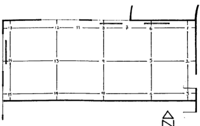
Fig. 3.3. Required illuminance ratios among surfaces in educational facilities.. 43 Fig. 3.4. Required reflectances for surfaces in educational facilities...44 Fig. 4.1. General layout of the studios...52 Fig. 4.2. Plan and measurement locations for the thermal environment...59
(Studio F207)
Fig. 4.5. Thermal sensation (Studio F207)...61 Fig. 4.6. Sensation of air movement (Studio F207)...61 Fig. 4.7. Sensation of discomfort due to radiant temperature asymmetry...62
(Studio F207)
Fig. 4.8. Plan and measurement locations for the thermal environment...64 (Studio F208)
Fig. 4.11. Thermal sensation (Studio F208)...66 Fig. 4.12. Sensation of air movement (Studio F208)...66
(Studio F208)
Fig. 4.14, Plan and measurement locations for the thermal environment... 69 (Studio F308)
Fig. 4.17. Thermal sensation (Studio F308)... 71 Fig. 4.18. Sensation of air movement (Studio F308)... 72 Fig. 4.19. Sensation of discomfort due to radiant temperature asymmetry... 72
(Studio F308)
Fig. 4.20. Plan and measurement locations for the thermal environment...74 (Studio F309)
Fig. 4.23. Thermal sensation (Studio F309)... 76 Fig. 4.24. Sensation of air movement (Studio F309)... 77 Fig. 4.25. Sensation of discomfort due to radiant temperature asymmetry... 77
(Studio F309)
Fig. 4.26. Plan and measurement locations for the visual environment...79 (Studio F207)
Fig. 4.29, Evaluation of the general illuminance level (Studio F207)...81 Fig. 4.30. Evaluation of the illuminance level on drawing tables... 82
(Studio F207)
Fig. 4.31. Occurrence of reflections on the drawing tables (Studio F207)...82 Fig. 4.32. Evaluation of the illuminance level on the drawings on walls... 83
(Studio F207)
Fig. 4.13, Sensation of discomfort due to radiant temperature asymmetry... 67
Fig. 4.35. Plan and measurement locations for the visual environment...84 (Studio F208)
Fig. 4.38. Evaluation of the general illuminance level (Studio F208)... 86 Fig. 4.39. Evaluation of the illuminance level on drawing tables...86
(Studio F208)
Fig 4 40. Occurrence of reflections on the drawing tables (Studio F208)... 87 Fig. 4.41. Evaluation of the illuminance level on the drawings on walls... 87
(Studio F208)
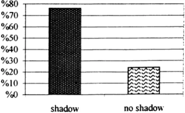
Fig. 4 42. Occurrence of reflections on the drawings on walls (Studio F208). . . .88 Fig. 4 43. Occurrence of shadows on the drawing tables (Studio F208)... 88 Fig. 4.44. Plan and measurement locations for the visual environment... 89
(Studio F308)
Fig 4.47. Evaluation of the general illuminance level (Studio F308)... 91 Fig. 4.48. Evaluation of the illuminance level on drawing tables...91
(Studio F308)
Fig. 4.49. Occurrence of reflections on the drawing tables (Studio F308)...92 Fig. 4.50. Evaluation of the illuminance level on the drawings on walls... 92
(Studio F308)
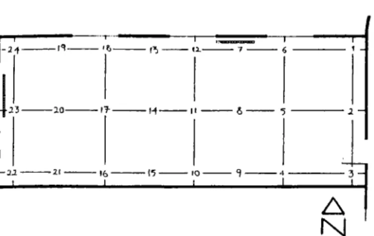
Fig. 4^51. Occurrence of reflections on the drawings on walls (Studio F308). . ..93 Fig. 4.52. Occurrence of shadows on the drawing tables (Studio F308)... 93 Fig. 4.53. Plan and measurement locations for the visual environment... 94 Fig. 4.34. Occurrence of shadows on the drawing tables (Studio F207)...84
Fig. 4.57. Evaluation of the illuminance level on drawing tables...96
(Studio F309) Fig. 4.58. Occurrence of reflections on the drawing tables (Studio F309)... 96
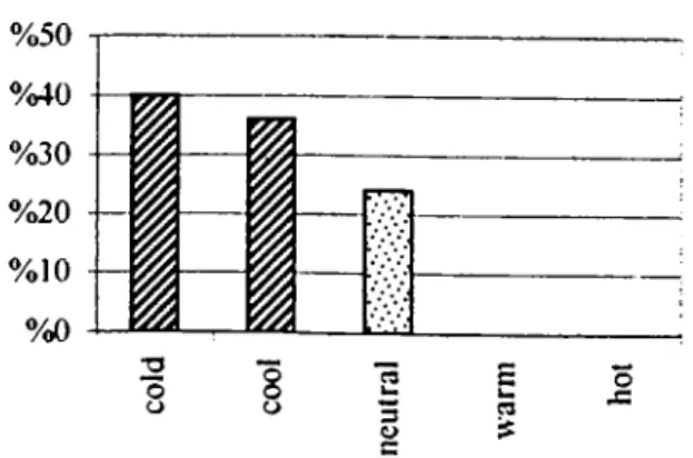
Fig. 4.59. Evaluation of the illuminance level on the drawings on walls... 97
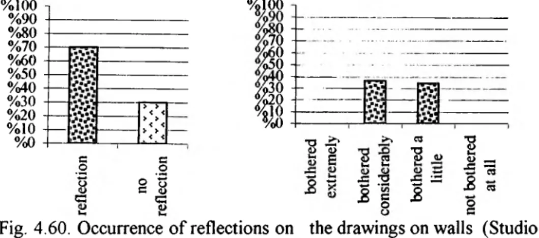
(Studio F309) Fig. 4.60. Occurrence of reflections on the drawings on walls (Studio F309)...97
Fig. 4.61. Occurrence of shadows on the drawing tables (Studio F309)... 98
Fig. 4.62. Sound pressure level analysis (Studio F207)...99
Fig. 4.63. Evaluation of outside noise (Studio F207)...99
Fig. 4.64. Evaluation of inside noise (Studio F207)... 100
Fig. 4.65. Sound pressure level analysis (Studio F208)... 101
Fig. 4.66. Evaluation of outside noise (Studio F208)... 101
Fig. 4.67. Evaluation of inside noise (Studio F208)... 102
Fig. 4.68. Sound pressure level analysis (Studio F308)... 103
Fig. 4.69. Evaluation of outside noise (Studio F308)... 104
Fig. 4.70. Evaluation of inside noise (Studio F308)... 104
Fig. 4.71. Sound pressure level analysis (Studio F309)... 105
Fig. 4.72. Evaluation of outside noise (Studio F309)... 106
Fig. 4.73. Evaluation of inside noise (Studio F309)... 106
Appendix C ...146
Fig. 4.3. Plan of Studio F207... 147
Fig. 4.56. Evaluation of the general illuminance level (Studio F309)... 95
Fig. 4.10. Iso-plane radiant temperature curves for Studio F208... 150
Fig. 4.15. Plan of Studio F308... 151
Fig. 4.16. Iso-plane radiant temperature curves for Studio F308... 152
Fig. 4.21. Plan of Studio F309... 153
Fig. 4.22. Iso-plane radiant temperature curves for Studio F309... 154
Appendix D... 155
Fig. 4.27. Plan of Studio F207...156
Fig. 4.28. Iso-illuminance curves for Studio F207...157
Fig. 4.36. Plan of Studio F208... 159
Fig. 4.37. Iso-illuminance curves for Studio F208...160
Fig. 4.45. Plan of Studio F308... 162
Fig. 4 46. Iso-illuminance curves for Studio F308...163
Fig. 4.54. Plan of Studio F309...165
Fig. 4.55. Iso-illuminance curves for Studio F309...166
LIST OF TABLES
Table Page
Table 3,1, Maximum allowable sound levels in occupancies... 50
Table 4 4, Thermal environment analysis (Studio F207)... 60
Table 4,8, Thermal environment analysis (Studio F208)... 65
Table 4,12, Thermal environment analysis (Studio F308)... 70
Table 4,16, Thermal environment analysis (Studio F309)... 75
Table 4,19. Visual environment analysis (Studio F207)...80
Table 4.22. Visual environment analysis (Studio F208)...85
Table 4.25. Visual environment analysis (Studio F308)... 90
Table 4 28. Visual environment analysis (Studio F309)... 95
Appendix A...117
Table 2 .1. Metabolic rates of different activities...118
Table 2.2. Thermal insulation properties of various types of clothing...119
Appendix B...121
Table 4.1. Air temperature data (Studio F207)...122
Table 4.2. Surface temperature data (Studio F207)... 123
Table 4.3. Plane radiant temperature data (Studio F207)...124
Table 4.5. Air temperature data (Studio F208)... 125
Table 4.6. Surface temperature data (Studio F208)... 126
Table 4.7. Plane radiant temperature data (Studio F208)...127
Table 4.9. Air temperature data (Studio F308)...128
Table 4.10. Surface temperature data (Studio F308)... 129
Table 4.11. Plane radiant temperature data (Studio F308)... 130
Table 4.13. Air temperature data (Studio F309)... 131
Table 4.14. Surface temperature data (Studio F309)... 132
Table 4.15. Plane radiant temperature data (Studio F309)...133
Table 4.17. Table-top illuminance data (Studio F207)... 134
Table 4.18. Wall illuminance and luminance data (Studio F207)... 135
Table 4.20. Table-top illuminance data (Studio F208)... 136
Table 4.21. Wall illuminance and luminance data (Studio F208)... 137
Table 4.23. Table-top illuminance data (Studio F308)... 138
Table 4.24. Wall illuminance and luminance data (Studio F308)... 139
Tablé 4.26. Table-top illuminance data (Studio F309)... 140
Table 4.27. Wall illuminance and luminance data (Studio F309)... 141
Table 4.29. Sound pressure level data (Studio F207)... 142
Table 4.30. Sound pressure level data (Studio F208)... 143
Table 4.31. Sound pressure level data (Studio F308)... 144
1. INTRODUCTION
1.1. General Approach to the Problem
The physical environment includes three main elements which are climate, light and sound These elements, which have a complex relationship, all act directly upon the human body. The human body either absorbs them or tries to counteract their effects, which result in physical and psychological reactions so as to provide biological equilibrium Man tries to adjust himself to his environment by using minimum amount of energy, and the conditions which provide this situation are defined as the "comfort zone". In the comfort zone, most of the energy of man can be used for productivity (Olgyay, 14-15).
The main instrument for satisfying comfort requirements is the shelter, which was first created by the primeval men to build enclosed spaces having an internal environment different from the external climate (Chalkley and Cater, 13). A shelter modifies the natural environment so as to provide optimum conditions for man to live in. To provide this requirement, the shelter should filter, absorb or repel environmental elements according to their beneficial or adverse effects on man's comfort (Olgyay, 15).
Buildings, which are also shelters, create environments for people to live and work in, and they aim at providing occupant satisfaction. The interior environment is
affected by both the influences transmitted by the building envelope, and the influences generated within the building or by its control systems (Ruck, 263). In order to create interior environments which are completely suitable for the activities they involve, some requirements have to be met. These requirements relate to environmental comfort conditions, the components of which are thermal, visual and acoustical comfort. The important point here is that, the effects of heat, light and sound cannot be considered as isolated elements in building design. Because of that reason, it is necessary to consider their interactions with one another and their combined effects on human comfort (Smith, 48-49; and Ruck, viii).
The aim of creating interior climates is to provide thermal comfort, which is defined by the EN/ISO 7730 Standard (5) as "that condition of mind which expresses satisfaction with the thermal environment". Thermal comfort studies deal with the effects of climatic impact on human response. The important point here is that, it is not possible to satisfy everyone simultaneously because of biological, emotional and physical differences among people. Therefore, it is necessary to provide conditions which will satisfy the highest possible percentage of the group.
The goal of architectural lighting as explained by Egan (Concepts in Architectural
Lighting 41) is to create the visual environment that best accommodates the
functions intended. In spaces where visual tasks are carried out, the provision of visual performance is the basic consideration, but it is insufficient when subjective assessments of people are considered, and therefore, it is also necessary to provide visual satisfaction in terms of comfort. A visually comfortable environment is defined by Ruck (40) as an environment where an eye task can be quickly and easily
performed without distraction or the creation of stress.
In order for a building to provide the most suitable environment for its occupants, acoustical comfort should also be provided as well as thermal and visual comfort. Although the reaction of people towards their thermal and visual environments is more or less passive, they have a direct interaction with their acoustical environment by means of speaking, singing, using devices, etc (Lawrence, 60). The basic aim of the acoustical environment in order to provide acoustical comfort is to be responsive to the activities inside the building, which requires providing clear communication, privacy, and a lack of acoustical interference as mentioned by Rabinowitz (G-1).
1.2. Aim of the Study
This study is a field study which aims at evaluating the existing environmental comfort conditions in a built environment. A building type, where occupant satisfaction in terms of environmental comfort is very important, is educational buildings. The reason of this importance is that, environmental comfort conditions have a significant role in learning by providing the well-being and satisfaction of the students (Çerefhanoglu, 223). Therefore, it is decided to evaluate a learning environment in terms of environmental comfort conditions.
For this purpose, four design studios at FF Building of the Interior Architecture and Environmental Design (lAED) Department of the Faculty of Art, Design and Architecture at Bilkent University in Ankara, Turkey are chosen as the site, and the students of these studios are chosen as the subjects of this research. The reason of analyzing design studios is that, these environments are the special classrooms in
design and art education, where the students spend a great portion of their time Design studio involves three main activities, which are the thinking process of design, critics about the design ideas, and preparing presentations such as drawing, painting, model making, etc. In other words, a design studio functions as both a learning center and a complex social organization.
The human factor is the most important consideration in building design. Therefore, the feelings of people are very important, and the values obtained by instruments are not enough to explain what people should feel (Ruck, vi). Therefore, the study consists of two parts; the physical measurements of environmental comfort parameters and the subjective responses of the occupants. The aim of taking measurements is to determine the existing environmental conditions in order to compare the obtained values with the relevant standards. Subjective responses of the occupants, that is their feelings, are evaluated by a questionnaire. At the end, the degree of comfort determined by the measurements are compared with the analysis of the questionnaires.
1.3. Structure of the Thesis
This study consists of five chapters including the introduction and conclusion parts. In the Introduction, the environmental comfort conditions which are examined in this study are introduced, and their importance in building design are mentioned. Besides, the aim of the study and the structure of the thesis are explained in this section.
elements of environmental comfort which are thermal, visual and acoustical comfort are introduced. After the definitions of the terms are given, the parameters affecting them are explained.
There are limited ranges of heat, light and sound which provide thermal, visual and acoustical comfort. These limits are mainly determined by the capabilities of man's visual and hearing systems, and his ability to make physiological and behavioral adjustments so as to provide a balance between the body and the environment as mentioned by Ruck (262). In the third chapter, Environmental Comfort Standards for the Design Studio, after the definition of the design studio in architectural education is made, the standards for the parameters explained in the second chapter are given. The standard values are compiled from the relevant standards of International Organization for Standardization (ISO), Catalogue of European Standards (CEN), American Society of Heating, Refrigerating and Air-Conditioning Engineers (ASHRAE), International Commission on Illumination (CIE), the Ministry of Public Works - Housing, and the Ministry of Environment.
In the fourth chapter which deals with a case study, first the determined design studios are described. As a next step the parameters of the field study are explained. The chapter ends with the analysis of the physical measurements of environmental comfort parameters and questionnaire responses.
The Conclusion is the last chapter, where the findings of the research are discussed and recommendations for the following researches are pointed out.
2. ENVIRONMENTAL COMFORT CONDITIONS
In this chapter, the components of environmental comfort will be introduced. First, the definitions of the terms will be given, and then the parameters affecting them will be explained.
2.1. Thermal Comfort
The ambient environment affects man both physically and emotionally, so it has an important role in building design. Therefore, one of the basic aims of the building designer is to create an environment which is suitable for all the human activities that will take place both inside and outside the building. In order to provide this inside the building, the designer should aim at creating an environment which is perceived by the occupants as being thermally comfortable (CEC, 59). O'Callaghan (43) mentions that intellectual, manual and perceptual performance is the highest only when the environment is evaluated as thermally comfortable.
2.1.1. Definition of Thermal Comfort
From ancient times till today, man has always aimed at creating a thermally comfortable environment, and this can be observed in building traditions around the world (INNOVA, 2). Today, because of the growing mechanization and industrialization of society, people spend most of their time in an artificial climate. Recent trends, therefore, depend upon the production of artificial interior climates,
The aim of creating artificial climates is to adjust the thermal environment so that each individual is in thermal comfort, and thermal comfort is defined in the EN/ISO 7730 Standard (5) as "that condition of the mind which expresses satisfaction with the thermal environment". Thermal comfort studies deal with the effects of climatic impact on human response According to O'Callaghan (43), an environment can be called a thermally comfortable one if the occupants experience no heat stress or thermal strain, that is a neutral state is present in which no action is necessary to maintain the heat balance of the body. Benzinger (442), on the other hand, explains the condition of thermal comfort as a state in which there are no driving impulses to correct the environment by behavior. Another explanation of the term made by Givoni (54) evaluates thermal comfort as the absence of irritation and discomfort due to heat or cold, and as a state involving pleasantness, and similarly, INNOVA (4) mentions that there should be no type of thermal discomfort in order for man to consider the environment comfortable. Besides, Commission of the European Communities (CEC, 59) defines comfort as the sensation of complete physical and mental well-being.
and this causes an increased interest in the environmental conditions, that is in the climates which are aimed to be created (Fänger, 13).
The biological, emotional and physical characteristics of the occupants also affect the sensation of comfort, so the control of the designer in creating a comfortable environment is limited. Because of these variations among people, everyone cannot be satisfied simultaneously when they are subjected to the same climatic conditions. Therefore, what should be done by the designer is to create optimal thermal comfort
2.1.2. Parameters Affecting Thermal Comfort
In order to provide health, well-being and comfort, one of the basic requirements is the maintenance of thermal equilibrium between the human body and its environment. For providing this equilibrium, the temperature of the core tissues of the body needs to be kept within a narrow range, regardless of the wide variations in the external environment (Givoni, 19).
Basic thermal heat exchange factors are conduction, convection, radiation and evaporation, and the direction of heat flow may be either to or from the body (Flynn, Segil and Steffy, 90). Usually very little heat exchange occurs by conduction which takes place by physical contact. Convection, which takes place between the human body and surrounding air causes heat transfer by motion of air. Radiation occurs by electromagnetic waves and takes place between the human body and its surrounding surfaces, that is between two physical objects. Evaporation is caused by change of moisture into vapor.
for the majority of the group, that is conditions which provide thermal comfort for the highest possible percentage of the group (Fänger, 13; and CEC, 59).
The body uses the food consumed, by the process of metabolism to produce energy. In other words, the human body converts food into energy, and the rate of this conversion depends on the body's activity. When work is performed by the body, most of this energy is transformed into heat, and the rest, which forms only a small part, is used for mechanical work. In order to maintain a stabilized inner body temperature which is around 37 °C, the body should provide a balance between
There are many factors which determine the conditions that provide the achievement of such a balance, that is, sensation of thermal comfort. These factors can be classified into two groups: personal (individual) parameters and environmental parameters (Givoni, 19). Personal parameters involve activity level or metabolic rate, and thermal resistance of clothing of the subjects (Fänger, 15; Hensen, 309; CEC, 60). Environmental parameters, the second group, which are directly dependent on building design and heating and cooling systems, consist of air temperature, mean radiant temperature, air velocity and relative humidity. The important point here is that, all of these parameters affect man's thermal state and comfort simultaneously, that is they have a combined effect on the human body. Therefore, it is not possible to consider the effect of any one of them independently (Fänger, 15), since the effect of each parameter and the necessary requirements depend on the level and conditions of the other factors (Fänger, 5).
internal heat production and the heat losses or gains to and from the environment (Givoni, 19).
2.1.2.1. Personal Parameters Activity Level or Metabolic Rate
Metabolism is the process by which food and oxygen are combined in the body by the process called oxidation, and the energy necessary for the functions of various organs in the body is produced (Givoni, 21). Metabolic rate, which is the main source of body's heat, therefore, can be defined as the amount of energy produced by the oxidation of food elements within the human body per unit time (Fänger, 23).
The factor influencing the metabolic rate is the activity level, the unit of which is mets (metabolic units), that is watts per square meter of body surface area. 1 met is the rate of heat produced, that is the metabolic rate of a seated person when relaxing,
which corresponds to 58.15 w/m^ of body surface area (CEC, 60).
For a given level of activity, the factors affecting metabolic rate are age, sex and the size and weight of the body. The last two factors cause variations in the metabolic rate and in order to eliminate these variations, metabolism may be expressed per square meter of the surface area or per kg of the weight of the body. For an average
man, the surface area of the body is taken as 1.86 m^ and the weight is accepted as 70 kg. The metabolic rate can be determined by measuring the oxygen consumption of the body (Givoni, 22).
The metabolic rates for various activities are given in Table 2.1 on page 118 at Appendix A.
Thermal Resistance of Clothing
There is an exchange of heat and moisture between the surface of the skin and the environment by convection and radiation. The function of clothing is to form a resistance to this exchange (O'Callaghan, 49), and to interfere with the process of sweat evaporation. Besides, it also reduces the sensitivity of the body to variations in air temperature and velocity. The effect of air temperatures lower than 35 °C is a reduction in the rate of "dry" heat loss from the body by producing a heating effect, and the reason of this is that, less body surface is exposed since it is covered with clothing. Air temperatures higher than 35 °C, on the other hand, causes a more
complicated effect. Not only the "dry" heat gain from the environment is reduced by the clothes, but also the humidity in the clothing is increased and the air velocity over the skin is reduced since the body is covered with clothing, and this results in a reduction of the cooling obtained from sweat evaporation (Givoni, 68).
Since clothing forms a thermal insulation between man and his environment, it is classified according to its insulation value. The unit used for measuring clothing's
insulation is m2°C/w or the unit of thermal resistance called the "do". 1 do, which
is 0.155 m2°C/w (Lechner, 30 and INNOVA, 8) or 0.18 ^Chm^/kcal (Givoni, 68), represents roughly the thermal resistance of a winter business suit (CEC, 60).
The factors which affect the thermal insulation provided by the clothing are the thermal resistance of the fabrics, and stiffness and fit of the garments. Because of this reason, this insulation should be determined by the help of direct measurements of the dry heat exchange of subjects who are wearing the clothes (Givoni, 68).
The thermal insulation properties of various types of clothing are given in Table 2.2 on page 119 at Appendix A.
2.1.2.2. Environmental Parameters Air Temperature
Air temperature —the simplest practical index of cold or warmth (O'Callaghan, 47)— is the dry-bulb temperature of the environmental air under ordinary room conditions. The ambient air temperature, the unit of which is °C, is the determinant factor of the rate of the "dry" heat exchange of the body by convection. Up to 37°C the heat flow
is from the human body to the air, and above this value the direction of the flow reverses (Lechner, 28). The factors which affect the rate of this heat exchange are air velocity and clothing (Givoni, 60).
It is possible to measure air temperature by a liquid in glass thermometer, a thermocouple, or an electric resistance sensor (including a thermistor). When the sensor is placed in a room, the value it shows is between air temperature and mean radiant temperature. In order to reduce the radiant error, the sensor should be made as small as possible. Another way to reduce the radiant error is to use a shield which is an open, polished aluminum cylinder around the sensor, or to increase the air velocity around the sensor by aspirating air through a tube in which the sensor is placed (Fänger, 140).
Mean Radiant Temperature (MRT)
The mean radiant temperature is an average temperature of the surrounding surfaces, therefore it is much more influential on human comfort than air temperature (CEC, 61). Mean radiant temperature, the unit of which is °C, is defined in relation to a person in a given body posture and clothing placed at a given point in a room, as “the uniform temperature of black surroundings which will give the same radiant heat exchange with the person as the actual case under study” (Fänger, 43). Egan
{Concepts in ITiernial Comfort 6), on the other hand, defines the mean radiant
temperature as "a weighted average of the various radiant influences in a space".
The definitions mention that, it is not enough to measure the temperatures and areas of all surfaces in a room to calculate mean radiant temperature. The reason of this is
that, this parameter is also a function of position since angle factors between emitting and receiving surfaces depend upon their relative locations (Egan, Concepts
in Thermal Comfort 6).
Mean radiant temperature at a point in a room depends on the temperatures of all the surrounding surface areas in the thermal view of the point, and it affects the rate of heat gains and losses by radiation. Measuring the mean radiant temperature precisely is difficult, since it represents the shape and surface radiative characteristics of the human body with respect to surrounding surfaces.
One method to measure the mean radiant temperature is to measure the surface temperature of ceiling, walls, floor, etc. using thermocouples or thermoradiometer, and then calculate the mean radiant temperature using the formula derived by Fänger at different locations using the angle factor diagrams he has developed. This method, needs a lot of calculation work after the measurements are taken (Fänger, 141).
Another method involves using the globe thermometer, which is the mostly used instrument to determine the mean radiant temperature. It consists of a black spherical shell having a thermal sensor (mercury in glass bulb, thermocouple, thermistor) in the center of the globe, by the help of which, the mean temperature of the globe is determined. It is then possible to calculate the mean radiant temperature using the globe temperature, the air temperature and the air velocity (Fänger 141-2 and CEC, 61).
Air Velocity
Air velocity has a significant effect on thermal comfort by removing the moisture and heat on the surface of the body (Egan, Concepts in Thermal Comfort 12). In other words, air velocity affects heat loss which occurs by convection and evaporation which, in turn, affects the cooling efficiency of sweating (Givoni, 65-9) Since air velocity affects convective heat loss from the body, air at a greater velocity seems cooler. People are sensitive to changes in air speed, the source of which may be natural convection, a fan or draught (forced convection) (Meier, 3). The unit used to measure air velocity is m/s.
In order to measure air velocity, the most commonly used instrument is the thermal anemometer which is able to measure the small velocities normally present in rooms, that is 0-0 5 m/sec. The important point here is the duration of the measurements. In order to obtain a reasonable mean value, the measurements should last for a suitable period such as 3 - 5 minutes. In cases where a small time interval is present, the mean value of a series of individual readings should be determined at some time intervals, or by the help of a recorder or an electric integrator. Another instrument that can be used is the silvered katathermometer, since it is possible to calculate the mean air velocity in the measuring period by the kata-value and air temperature. In cases of less exact measurements, smoke technique can also be used which· involves timing the movement of a smoke puff. For this purpose, smoke ampoules available in various types are used (Fänger, 140-1).
Relative Humidity (RH)
on the body. It is the influential factor in the evaporative capacity of the air which in turn affects the cooling efficiency of sweating. It is possible to express the humidity in terms of relative humidity, absolute humidity, specific humidity or vapor pressure (Givoni, 63).
"Relative humidity in %, is the amount of moisture in air compared to the maximum amount that can exist at a given temperature without condensation" (Egan, Concepts
in Thermal Comfort 8). The humidity of the air has a very important effect on the
evaporation of sweat (Lechner, 28).
The effect of humidity on persons who are in thermal comfort is relatively moderate. The necessary temperature drop to counteract a change from absolutely dry air (rh=0%) to saturated air (rh=100%) is approximately 1.5-3.0°C (Fänger, 43). Besides, the humidity of the air has a little effect on thermal sensations at moderate air temperatures (15 - 25 °C) under steady-state conditions, that is when a person stays in the same space for a long time: an increase of 10% in relative humidity will have the same effect as an only 0.3 °C rise in air temperature. On the other hand, when a person moves from indoors to outdoors or from one space to another with a different humidity, that is under transient conditions, the change in humidity can have a 2 - 3 times greater thermal effect. The changes in humidity levels have also a considerable effect on thermal comfort in warm environments with an air temperature greater than 30 °C (CEC, 62).
The instruments which can be used to measure the vapor pressure are psychrometer, dew-point apparatus, hair hygrometer, or electrolytic hygrometer. It is sufficient to
measure the humidity at one location only, since the vapor pressure will not show great variations throughout the room (Fänger, 142).
2.1.3. Local Discomfort
Thermal comfort implies satisfaction with the thermal environment. In order to provide thermal comfort, the first necessary condition is thermal neutrality, where an individual desires neither a warmer nor a colder environment. However, providing thermal neutrality is not necessarily a sufficient condition for comfort. It is also necessary that, no particular part of the body should be uncomfortably warm or cool. In other words, unilateral heating or cooling of the body, that is local discomfort should also be avoided so as to prevent dissatisfaction with the thermal environment (CEC, 63). When local discomfort is present, it is not possible to remove it by raising or lowering the temperature of the enclosure, instead, the cause of the localized over-heating or cooling should be removed (INNOVA, 14).
The causes of local discomfort can be classified into four groups: Draught, asymmetric thermal radiation, large vertical air temperature differences, and uncomfortable floor temperature.
The first cause, the draught, means the unwanted local cooling of the body caused by air movement, that is local convective cooling of the body. Draught is a serious problem not only in many ventilated buildings but also in automobiles, trains and aircraft. The most sensitive parts of the body to draught are the unclothed parts. Therefore, draughts are generally felt only on the face, hands and lower legs. The factors affecting the amount of heat loss from the skin caused by draughts are
average air velocity, as well as the turbulence intensity of the airflow and the air temperature (INNOVA, 15-6).
Asymmetric or non-uniform thermal radiation, the second cause of local discomfort, involves cooling or heating of parts of the body by radiation as a result of which, one side of the body becomes warmer or cooler than the other. Asymmetric thermal radiation in a space may occur because of conditions like direct exposure to sunshine or being close to large window areas, uninsulated walls, cold or warm machinery, or improperly sized heating panels on the wall or ceiling, which cause an uncomfortable feeling for the body. The parameter used to describe this non uniformity in the thermal radiation field is the radiant temperature asymmetry, which is defined as the difference between the plane radiant temperature (tpr) of the two opposite sides of a small plane element (INNOVA, 17).
There are two ways to determine the parameter radiant temperature asymmetry. One way is to measure tpr in two opposite directions using a transducer that integrates the incoming radiation on to a small plane element from the hemisphere covering it. The other way is to measure the temperatures of all the surrounding surfaces and then to calculate the radiant temperature asymmetry as described by INNOVA (18).
The third cause of local thermal discomfort is large vertical air temperature differences, that is excessive temperature differences between the head and ankles (which result in cold feet and warm head at the same time) (INNOVA, 18). In most spaces in buildings, an increase in the air temperature occurs with height above the floor. If the gradient is large enough, local warm discomfort can occur at the head
and/or local cold discomfort can occur at the feet, although thermal neutrality is present for the body as a whole. The opposite case in which the air temperature at head level is lower than that at ankle level will not be as critical for the occupants. In other words, a much greater differences could be tolerated in case when head is cooler (ASHRAE, 8.21).
Uncomfortable floor temperature is the last cause of local thermal discomfort as a result of which feet become too warm or too cool. The causes of the local discomfort of the feet can often be too high or too low floor temperature, and this occurs because of the direct contact between feet and floor. The discomfort is caused by the heat loss from the feet, so it is incorrect to talk about the thermal discomfort caused by the floor temperature The heat loss depends on parameters other than the floor temperature, such as the conductivity and the heat capacity of the material the floor is made from and the type of covering worn on the feet (INNOVA, 19).
2.1.4. Evaluation of Thermal Environments
It is possible to evaluate the quality of the thermal environment only when both the local and general thermal comfort parameters are investigated (INNOVA, 15). Thermal comfort is defined as "that condition of mind in which satisfaction is expressed with the thermal environment", as mentioned in a previous section. Since comfort is a "condition of mind", it is necessary to use empirical equations to form a relation between comfort perceptions and specific physiological responses. The thermal sensation scale used in these equations is referred to as the ASHRAE thermal sensation scale, and is the same as the Predicted Mean Vote (PMV) scale described later. This scale is as follows: +3 hot, +2 warm, +1 slightly warm, 0
neutral, -1 slightly cool, -2 cool, -3 cold (ASHRAE, 8.16).
The PMV index is used to predict the mean response of a large group of people according to the ASHRAE thermal sensation scale. Fänger related PMV to the imbalance between the actual heat flow from the body in a given environment and the heat flow required for optimum comfort at the specified activity (ASHRAE, 8.17).
2.2. Visual Comfort
Ruck (40) states that we receive information from our environment, 80% of which is of a visual nature since it is obtained by our eyes. The primary objectives in lighting design depend on the function of the interior for which the design is made. The spaces in which visual tasks are carried out are named as working interiors, and the main purpose of the lighting in such areas is to provide the performance of the visual tasks taking place there, that is visual performance. Visual performance is defined by Philips Lighting (127) as "the speed at which the eyes function and the accuracy with which a visual task can be carried out".
Although visual performance is the basic consideration in working interiors, it is observed that, lighting recommendations for working interiors, which take only visual performance parameters into account, are often insufficient. The reason of this insufficiency is that, in fact, most of the practical tasks are not the same as they are defined in the standards about lighting, and the same task shows variances in different working interiors. The studies conducted about the subjective assessment of the levels of illuminance and luminance show that another very
important design consideration in lighting is the creation of visual satisfaction in terms of comfort and pleasantness, and this requirement should be met in every environment regardless of the function being considered (Philips Lighting, 128).
2.2.1. Definition of Visual Comfort
Egan {Concepts in Architectural Lighting 41) defines the goal of architectural lighting as "to create the visual environment that best accommodates the functions intended (such as work or relaxation), and he mentions that "visual comfort results when we are able to receive the clear visual information that we instinctively or consciously want to know".
A visually comfortable environment is defined by Ruck (40) as "an environment in which an eye task such as reading a book or searching for an object is quickly and easily performed without distraction or the creation of stress", and such an environment is explained as one "that facilitates seeing by providing adequate illuminance, ensuring the appropriate distribution of luminances and directional lighting, and eliminating distraction and stress, in the accomplishment of visual tasks, generally caused by glare". The factors which influence the way wee see things are the quantity of light showing the amount of light, and quality of light received by our eyes, which requires the avoidance of glare, and these two factors are rnentioned by Ruck (57) as the parameters affecting visual comfort. The factors used to describe the quantity and quality of lighting, called lighting parameters, are listed by Philips Lighting (129) as lighting level (illuminance), luminance distribution, glare, modelling, and color. Besides, the factors which affect the subjective judgments of visual comfort are listed in the lESNA Lighting Handbook,
as "room size and shape, room reflectances, illuminance levels, luminaire characteristics, number and location of luminaires, luminance of the entire field of view, observer location and line of sight, and differences in individual glare sensitivity" (Erhardt, 6).
2.2.2. Parameters Affecting Visual Comfort
When the different definitions of visual comfort, mentioned above, are analyzed, it is observed that, the parameters determined by all of them can be classified into two main groups: quantity of light and quality of light.
2.2.2.1. Quantity of Light
The quantity of light is represented by the lighting level, when interior lighting is considered, and the parameter which expresses the lighting level is illuminance (Philips Lighting, 129).
Illuminance
The unit used to define the power or rate at which light is emitted by a light source is lumen. The lumens emitted by a light source illuminate a surface, and in order to be able to compare different illumination schemes, light falling on equal areas should be considered. Therefore, illuminance is "a measure of the number of lumens falling on each square meter of a surface" (Lechner, 252), and defined as "the luminous flux incident on unit area of a surface". The unit of illuminance is the lux which is equal to lumen per square meter.
(Lechner, 252). An illuminance meter should match the sensitivity of the human eye by being color corrected. Besides, in order to measure illuminance accurately, it should be cosine corrected (Lechner, 507).
2.2.2.2. Quality of Light
Quality of light in an environment is determined by the distribution of luminances in a visual environment. The term has a positive meaning and it indicates that all the luminances provide visual performance, visual comfort, ease of seeing, safety and aesthetics for the involved specific visual task (lES, Rl-24, 25).
Luminance
For a specific task, there must be enough light to allow the work to be done safely and efficiently (Sorcar, 10). In fact, what we see is not illuminance; we see the light reflected from surfaces. The factors which determine the brightness of what we see are both the illuminance and the reflectance of a surface. The brightness measured by a meter is called luminance and it refers not only reflected but also to emitted or transmitted light (Lechner, 252-3).
Luminance is defined by CIBSE (54) as “a term which expresses the intensity of the light emitted in a given direction by unit area of a luminous or reflecting surface”, that is the luminous intensity of a surface or an object (Egan, Concepts in
Architectural Lighting 233). It is the physical equivalent of what subjectively is
called brightness. The unit of luminance is the candela per square meter (cd/m^) (CIBSE, 54). The instrument used to measure luminance is called the luminance meter.
Luminance Ratios
There are limits for luminance relationships among various surfaces in the normal field of view in a space. Looking at a task provides the establishment of an adaptation level, and the eye's moving from one luminance to another requires a réadaptation to the new luminance level. The presence of a great difference between the two levels, causes a necessity for a period of time for the eye to adapt itself to the new situation. If the difference is too great, discomfort will occur caused by a transient change in pupillary opening and adaptation to the new level. These problems, which occur especially when large surfaces are present, can be avoided by keeping luminance differences between adjacent surfaces within acceptable limits (lES, A6-3).
Reflectance Factor
Reflection is defined by lES (Rl-25, 26) as "the process by which the incident flux leaves a surface or medium from the incident side, without change in frequency". The reflectance factor is used to determine how much of the light falling on a surface is reflected, and it is, therefore, an indication of the ratio of reflected flux to the incident flux, that is the ratio of luminance to illuminance. This factor shows only the amount of reflected light, it does not give information about how the light is reflected. The reflectance factor always has a value smaller than one, since the reflected light (luminance) is always less than the incident light (illuminance) (Lechner, 253).
Glare
greater than the luminance to which the eyes are adapted to, annoyance, discomfort, or loss in visual performance and visibility occur (lES, Rl-14). This “discomfort or impairment of vision experienced when part of the visual field (e g. sky or lamps) is excessively bright in relation to the general surroundings" is called glare, as defined by CIBSE (53). The factors which affect the magnitude of the sensation of glare are the size, position and luminance of a source, the number of sources and the luminance to which the eyes are adapted (lES, Rl-14).
There are two forms of glare, which are disability glare and discomfort glare. Disability glare is the form of glare the effects of which are the impairment of the ability to see detail, without always being accompanied by visual discomfort (CIBSE, 53). Therefore, such a glare causes a reduction in visual performance and visibility (lES, Rl-11). Discomfort glare, on the other hand, results in visual discomfort without necessarily interfering with the ability to see detail, that is visual performance or visibility (CIBSE, 53).
Glare may occur either in the form of direct glare, reflected glare or veiling reflection. Direct glare results when excessively bright parts of the visual field, such as high luminances or inadequately shielded light sources are in the field of view (CIBSE, 53). Therefore, "it usually is associated with bright areas, such as luminaires, ceilings and windows which are outside the visual task or region being viewed" (lES, Rl-10). Reflected glare, on the other hand, is "a term used to describe various visual effects, including reduction of contrast, discomfort and distraction produced by the reflection of light sources or other bright areas in glossy or smooth surfaces", as defined by CIBSE (53). When the light is reflected from a specular part
of the task itself, it is called a veiling reflection, and it results in substantial losses in task contrast, visibility and visual performance. The reason of these reflections' being differentiated from others is that, "they act as if a luminous veil is superimposed on the task". Veiling reflections cause some loss of contrast whatever the degree of the veil between the task and its proximate background is. The result of veiling reflections is a decrease in visual performance, although it is often not possible to detect them by the eye (lES, A6-5).
Color
The color qualities of a light source are determined by its color appearance and color rendering capabilities. The color appearance of a lamp refers to the apparent color of the light it emits, which may be described by its correlated color temperature, expressed in degrees Kelvin. The other factor used to simplify the description of a light source is its color rendering capabilities, and it is expressed in terms of color rendering index. Color rendering index (CRJ) is used to compare light sources with a standard source of white light. A CRI of 100 indicates a perfect match, while a CRl of 90 is accepted as quite good, and a CRI of 70 is also considered acceptable for not critical applications (Lechner, 255-7).
2.3. Acoustical Comfort
In order for a building to provide the most suitable environment for its occupants, acoustical comfort should also be provided as well as thermal and visual comfort. Although the reaction of people towards their thermal and visual environments is more or less passive, they have a direct interaction with their acoustical environment
by means of speaking, singing, using devices, machinery, etc. (Lawrence, 60).
2.3.1. Definition of Acoustical Comfort
Rabinowitz (G-1) defines the primary objective of the acoustical environment as "to be responsive to the activities within the building", and he mentions that this can be provided by supporting clear communication, and providing privacy and a lack of acoustical interference.
The acoustical environment of a space is determined by the physical geometry of the space, the materials used in its construction, and the factors which are effective in determining whether an acoustical environment is successful or not —the expected level of acoustical performance— are the type of the space and its intensity of use (Rabinowitz, F-1). Therefore, while the expected level of acoustical performance is the need for a safe environment in an industrial environment where prevention of noise-induced hearing loss is the main concern, in an environment such as a typical office, the expected level of acoustical performance may be comfort (AES, xi).
2.3.2. Parameters Affecting Acoustical Comfort
Rabinowitz (F-1) and AES (xi) discuss the quality of the acoustical environment in an enclosed space, that is the parameters of acoustical comfort in terms of three main characteristics. These characteristics, which are all quantifiable, are the ambient sound level, reverberation time, and attenuation which involves sound propagation or transmission within the space or sound transmission through walls, partitions, etc. The quality of the acoustical environment can be determined by direct measurements of these three criteria, which are then compared with accepted
standards of acoustical performance (Rabinowitz, F-2)
The parameter considered in this study is the ambient sound level The other two parameters could not be evaluated since the equipment necessary to measure them were not available. Because of this reason, only the ambient sound level will be explained in this section.
2.3.2.1. Ambient Sound Level
AES (8) defines ambient sound as "the composite value of airborne sound from all sources associated with a given environment", and this definition is explained by Cowan (271) as "the total noise level in the acoustic environment, usually including the noise source of interest". Besides, Rabinowitz (G-1) defines the term as a measure of the amount of existing background noise level.
The term sound level refers to a logarithmic ratio of sound power or other parameters proportional to sound power. The unit of sound level is the decibel (dB). In evaluating environments in terms of sound levels, overall and octave band measurements are the most commonly used types, and most noise measurements are in terms of sound pressure level. In an overall measurement, the sound environment is described by a single decibel value which considers all frequencies. However, human ear does not perceive all frequencies in the same way, and therefore, how we hear the sound is different from how a microphone does. Although the human audio frequency range covers a range between 20 Hz and 20 kHz, the frequencies to which people are most sensitive are between 200 Hz and 10 kHz (Cowan, 36). In order to consider these variations, weighting systems are used. The most common weighting
network, having an international use, is the A-weighting network, which provides considering the frequency sensitivity of the human ear in overall sound level measurements, and the unit used is dBA (Lawrence, 61).
According to AES (8), there may be three components of ambient sound level in buildings, and these are sources external to the building like traffic, aircraft, etc.; the acoustical output of the building systems (lighting, plumbing, mechanical and transportation), and sounds generated by the occupants including speech, circulation, movement of seats, closing of doors, etc. The important point here is that, the quantity of the sound generated by the occupants and their activities is often much greater than that produced by the building systems (AES, 9).
The instruments used to measure ambient sound levels are the sound level meter and the digital frequency analyzer (AES, 10). The sound level meter, which is very useful for measuring sound levels involves a microphone and suitable electrical equipment to convert the sound falling on the microphone into a meter reading which shows the sound-pressure level in decibels (Knudsen and Harris, 13-14). It is possible to measure overall sound levels as either linear or A-weighted values. A single number value is obtained by these measurements, and this value can be read directly from the sound level meter (AES, 10).
3. ENVIRONMENTAL COMFORT STANDARDS FOR THE
DESIGN STUDIO
There are limited ranges of heat, light and sound by the help of which, thermal, visual and acoustical comfort are provided. The factors which determine these limits are the capabilities of man’s visual and hearing systems, as well as his ability to make physiological and behavioral adjustments to provide a balance between the body and the environment (Ruck, 262). In this chapter, after defining the design studio in architectural education, the standards for the parameters of environmental comfort are given, considering the design studio. The sources which are used to compile the standards are those of International Organization for Standardization (ISO), Catalogue of European Standards (CEN), American Society of Heating, Refrigerating and Air-Conditioning Engineers (ASHRAE), International Commission on Illumination (CIE), the Ministry of Public Works - Housing, and the Ministry of Environment.
3.1. Definition of the Design Studio in Architectural Education
Design studios are the special classrooms in design and art education in which the design students spend most of their time. There are three main categories of activities in a design studio which are the thinking process of design, critics about design ideas (including juries), and preparing presentations such as drawings, paintings, model making, etc. All of these activities may take place either as
individual or group work. The individual work, which also involves the private design critics between a student and a teacher, is performed on the work surfaces belonging to each student. Group work in a design studio is similar to individual work except for the fact that, it requires a larger work space. Because of the diversity of activities in a design studio, the environment should be designed so that all the activities mentioned above can take place simultaneously, without interrupting each other.
Another important characteristic of the design studio is that, there is a living process within these environments, and this is the basic difference of a design studio from other classroom environments. In other words, design students spend a great portion of their times in the design studios not only during the class hours but also in their free time (Schön, 32). Therefore, the requirements for environmental comfort, the components of which are thermal, visual and acoustical comfort, should be carefully examined in designing these environments.
3.2. Standards for Thermal Comfort
Man’s intellectual, manual and perceptual performance is the highest when the environment is evaluated as thermally comfortable, as mentioned by O’Callaghan (43). Because of this reason, acceptable thermal comfort conditions should be determined for the design studios. The important point is that, comfort in an environment is complex and affected by all the personal and environmental parameters simultaneously. Therefore, in order to provide thermal comfort, all the criteria given in the following sections should be provided together (ANSI/ASHRAE 55, 3).