Research article
DURABILITY OF HISTORICAL MASONRY
REGARDING JOINT REPAIRING MEASURES –
PREDICTION BY MEANS OF NUMERICAL AND
ENGINEERING MODELS
Kubilay Kaptan
Disaster Education, Application and Research Center, Istanbul Aydin University E-mail: [email protected]
________________________________________________________________________
ABSTRACT
When repointing historic masonry, it is the quality of the bond between mortar and stones that decides on the lifecycle of the structure. Once the composite system or the mortar starts cracking, moisture can penetrate into the masonry and destroy the system. What mortar to use for what kind of masonry is normally an empirical decision. But in how far the mortar eventually selected is really suited for the purpose in question will not turn out until several years later. It is with this knowledge in mind that a simple engineering model has been developed, which is easy to use and which is to permit the likelihood of cracks to be assessed quantitatively. The model is based on calculations made for stresses occurring on the surface of the masonry and only requires a few material parameters. A combined, complex research model is being de-veloped, which is to provide for exact structural analysis. For this model, the temperature and moisture transport is calculated with the aid of an FDM program. The temperature and moisture fields thus determined are then transferred to an FEM program which uses the material models of Rots (1997), Lourenço (1996) and Van Zijl (2000) for stress and deformation calculation.
Keywords: Masonry, Engineering models, Historical, Masonry Structures, Durability.
________________________________________________________________________
1. INTRODUCTION
Conservation of historic structures normally involves rehabilitation of joints, and the jointing mortar has the function of providing weathering protection. In particular in case of rehabilitation measures extending far into the masonry, the mortar also has to be able to transmit forces. An essential condition for the durability of such repair meas-ures is that the bond between stone and joint mortar is of a good quality and does not show any cracks.
The decision as to what kind of mortar to use for joint repair measures in natural stone masonry of historic buildings is usually a question of experience, while trying to give due regard to preservation requirements. Whether or not the masonry mortar or joint mortar chosen is actually suited for the given kind of masonry often does not show until it has been in place for several years. A major criterion is the weather protection
particular on the crack-free bond between stone and joint mortar.
Even if a joint mortar itself has good weather protection properties, the mortar/stone flank bond region is a critical weak spot for the durability of masonry. Since the stones and the mortar in new joints tend to differ in their deformation behaviour (which is the result of differences in their thermal, hygral and mechanical properties), cracks are likely to occur between stones and mortar, or in the mortar itself. Material qualification tests alone do not suffice to predict the occurrence of cracks in the composite stone / mortar system.
To be able to assess the risk of cracking, a large number of tests have to be per-formed on composite stone / mortar elements. Since historic buildings are made from a variety of different stones (normally natural stones whose properties tend to vary considerably), the bond characteristics would have to be examined separately for each structure requiring rehabilitation. This would not only be very costly, but also rather time-consuming. Another aspect is that different kinds of mortar are generally used in a particular structure. Mortar in the base region will not be the same as that in the ris-ing masonry or on inclined surfaces. This large number of factors would increases the test requirements considerably.
However, if it should be possible to use models to predict the durability of new joints in historic masonry for defined boundary conditions, such costly and time consuming tests could be either limited or be avoided altogether. Broadly based parameter analy-ses made before starting any rehabilitation measures will then allow the suitability of a mortar to be reviewed for the application in question. Should the mortar be found to be inadequate, the properties of the mortar can be varied to decide what changes need to be made to produce a joint that is free from cracks.
2. CAUSES OF CRACKS
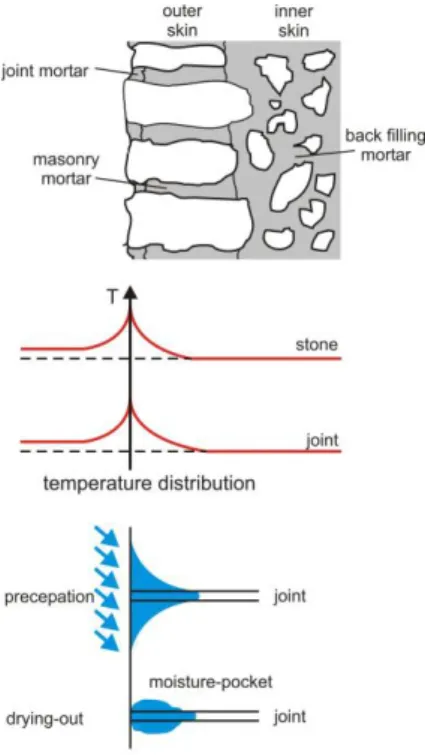
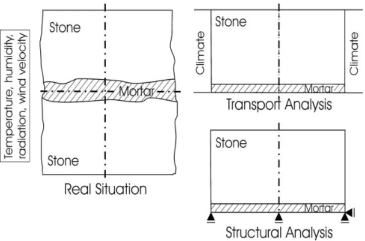
For the development of the composite structure models below, the cause for cracking must be known. The criteria primarily considered as a first step in developing the model are the mechanical/physical material properties and the residual and the restraint stress resulting from such properties. Stones and mortar are characterised by specific thermal and hygral behaviour. Irregular temperature and moisture distribution (see Fig. 1), which itself is the result of atmospheric conditions, produces constrained thermal and hygric strains.
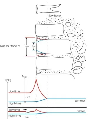
Figure 2: Deformation of natural stones in histo-rical masonry as a result of thermal elongation
Fig. 2 is a schematic representation of the thermal strains in natural stones at the surface of the masonry, which are produced by changes in ambient temperatures. During summer months, the surface of the natural stone facade heats up considerably due to its exposure to direct sunlight during the day. At night, the surface of the facade cools down to the temperature level of the ambient air. Temperature differences of up to 50 °C at the surface are therefore quite normal. This difference in temperature produces strains in the stones and the mortar, which because of the mutual deformation restraint in turn gives rise to restraint stress. In winter, the entire facade cools down to very low temperatures. The result are tensile stresses in the mortar and in the stones, and adhesive tensile stress in the bond region. Stresses acting on the bond primarily in near-surface regions of the masonry are hence a function of moisture and temperature fields and they are subject to stress relaxation. This means they not only region specific but also time specific characteristics.
The consequence of restrained deformation normal to the joint flank can be flank failure. Deformation along the joints is limited by internal constraints. The result are residual stresses which can make the mortar crack transverse to the joint. The bond resistance R is determined by the tensile strength of the stone ft,St and
of the mortar ft,Mo, and by the adhesive tensile strength ft,a. The lowest value is always the decisive one. The
tensile strength is determined by the moisture level and, in the case of the mortar, also by the time.
3. MODELS FOR CRACKING IN NEW JOINTS
3.1. Engineering model
The engineering model for the durability of the composite system natural stone / mortar joint in connection with repointing of historic masonry developed by Schmidt-Döhl and Rosásy (2000) is used as a simple means of modelling the bond behaviour. The engineering model starts from the assumption that stress that can lead to cracks is the result of irregular temperature and moisture distribution across the masonry cross section. Thermal and hygral strain at the surface is restrained by the inner masonry structure. The basic function of the model is to calculate stresses at the surface, starting from the simplifying assumption of a fully constrained composite stone / mortar element and maximum temperature difference:
0
,
S el pl C T
(1)Under conditions of full constraint, the sum total of all strain components has to be 0 at the surface. For the cases flank cracking (crack in parallel with the joint, Fig. 3) and mortar cracking (crack normal to the longitudinal direction of the joint, Fig. 4) the different strain components are examined more closely.
Figure 3: Cracking parallel to joint
Figure 4: Cracking normal to the joint
Crack initiation parallel to joint (side cracks)
Thermal strain T is calculated with the aid of the coefficient of thermal expansion T of mortar and stone,
the maximum temperature difference Tmax occurring between mortar and stone or the constraining action
of the inside of the masonry (cf. Figs. 1 and 2), and the percentage of area l0 taken up by mortar and stone:
)
1
(
0, max, , , 0 max, ,Mo Mo Mo T St St Mo T T
T
l
T
l
(2)Shrinkage strain S is calculated with the aid of the final degree of shrinkage S, of mortar and stone, and
the area percentage l0 of mortar and stone. The final degree of shrinkage is used for simplification, because
it is expected that the relative moisture in the mortar and stone surfaces decisive for cracking will very quickly follow any changes in the relative moisture of the ambient air and that the constraint-induced shrinkage strain will be produced at the surface:
)
1
(
0, , , , 0 , , Mo Mo S St Mo S S
l
l
(3)Elastic-plastic strain el,pl is the result of the actual stress t and the secant modulus Esec of mortar and stone,
and of the area percentage l0 of mortar and stone in the composite stone / mortar system. Respecting flank
failure, the model starts from series arranged mortar and stone:
St Mo Mo Mo Mo t pl el E E l l E sec, sec, , 0 , 0 sec, , ) 1 ( ) ) 1 ( ( , 0, , 0, st Mo st t Mo Mo Mo t t C E l C E l C (4+5)
Creep strain C is calculated from the actual stress t, the creep coefficients Ct of mortar and stone, the
modulus of elasticity E of mortar and stone, as well as the area percentage l0 of mortar and stone.
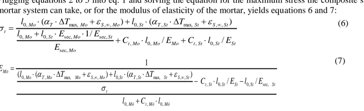
Plugging equations 2 to 5 into eq. 1 and solving the equation for the maximum stress the composite stone / mortar system can take, or for the modulus of elasticity of the mortar, yields equations 6 and 7:
St St St t Mo Mo Mo t Mo St Mo St Mo St S St St T St Mo S Mo T Mo t E l C E l C E E E l l T l T l / / / 1 ) ( ) ( , 0 , , 0 , sec, sec, sec, , 0 , 0 , , max, , , 0 , , max, , 0 (6) Mö Mö t Mö St St St St St t t St S St St T St Mo S Mo Mo T Mo Mö l C l E l E l C T l T l E , 0 , , 0 sec, , 0 , 0 , , , max, , , 0 , , max, , , 0 / / ) ( ) ( ( 1 (7)
Crack initiation normal to joint (mortar cracks)
The risk of crack propagation perpendicular to the joint is assessed by connecting mortar and stones in parallel rather than in series. When compared with the residual stress in the mortar, the influence of the stones on crack propagation in the mortar is insignificant. This is why in this case the engineering model is restricted to the mortar and does not consider a composite stone / mortar system. Again, considerations start from a fully restrained system and the maximum temperature difference.
The thermal strain is calculated with the aid of the thermal coefficient of expansion T of the mortar and the
maximum difference in temperature Tmax between mortar and the restraining masonry: Mo
Mo T
T
,
T
max,
S
S,,Mo (8+9)The shrinkage strain corresponds to the relevant final degree of shrinkage S, of the mortar.The
elastic-plastic strain follows from the actual stress t and the secant modulus Esec of the mortar
Mo t pl el
E
sec, ,
Mo Mo t t CE
C
,
(10+11)The creep strain C can be calculated from the actual stress t, the creep coefficient Ct of the mortar, and the
modulus of elasticity E of the mortar.
Plugging equations 8 to 11 into eq. 1 and solving the equation for the maximum stress the mortar can take, or for the modulus of elasticity of the mortar, yields equations 12 and 13.
Mo t Mo S Mo Mo T Mo t
C
T
E
, , , max, ,1
Mo S Mo Mo T Mo t t MoT
C
E
, , max, , ,)
1
(
(12+13)Implementation and application of the engineering model
Equations 6 and 7, as well as 12 and 13, form the basis for the engineering model which is applied in the form of a Microsoft Access® database. Respecting the variables in equations 2 to 5 and 8 to 11 the following distinctions can be made:
1. Parameters established on the structure : - Area percentage of mortar and stone
2. Parameters established experimentally or from databases - coefficient of thermal expansion T of mortar and stone
- final degree of shrinkage S, of mortar and stone
- maximum temperature differences T between mortar and stone
- creep coefficients Ct of mortar and stone
- modulus of elasticity of stone
Should these parameters not be established experimentally, they can be assessed with the aid of the engineering model or they can be imported from the data records in the database.
3. Values established with the engineering model and serving as a basis for mortar selection - stress t normal and perpendicular to the joint flank
- modulus of elasticity EMo of the mortar.
Stress t must not be greater than the strength of the mortar, the strength of the stone or the bond
strength.
It has been developed a graphical user interface using mortar and stone data available from literature and data compiled from our own investigations and analyses. This database can be used for rough parameter studies to be able to select mortars that promise to be a good choice for a given masonry, and it can alternatively be used to determine the requirements the intended mortar has to meet. For verification of the model, the cracking behaviour in the region of the joint of restrained two-stone bodies was examined for constant climatic conditions and for one-sided weather exposure (Schmidt-Döhl and Rosásy 2000).
A total of three test series were run, all of them using dolomite rock from the Harz mountains and green sandstone from Rüthen as natural stone, and mortar based on granulated blast-furnace slag and gypsum. Stone and joint deformations, and deformations beyond the joint were measured continuously, as were the
mortar and stone was determined gravimetrically once at the end of each test series. Changes in the mortar temperature were in addition measured at five points of a masonry section at depths of approx. 2.5, 5, 10, 35 and 60 centimetres.
Even though the model only starts from linear-elastic material behaviour (while considering time-specific deformation), experimentally determined results could be shown with a high degree of approximation. But the accuracy of the model is limited. Because it has so far been formulated as a deterministic model, it does, for instance, not account for the considerable variation of properties of natural stone. Much thought is at the moment being given to the possibility of automated parameter studies. These would also account for the variation in the mortar and stone properties, provided they have been stored in the database. Another aspect which is at the moment not included in the calculation is the bond shear strength, which is why shear stress perpendicular to the crack front is not accounted for. Neither does the model at the moment consider any chemical degradation processes and frost-induced processes, such as the degradation of mortar properties as a result of weathering. 0 0,1 0,2 0,3 0,4 0,5 0,6 0,7 R I KS R I Z R II KS R II Z R III KS R III Z
bond betw een three different gypsum -lim e m ortars tw o different bricks
te n s il e s tr e n g h t/ -s tr e s s i n [ N/ m m ²]
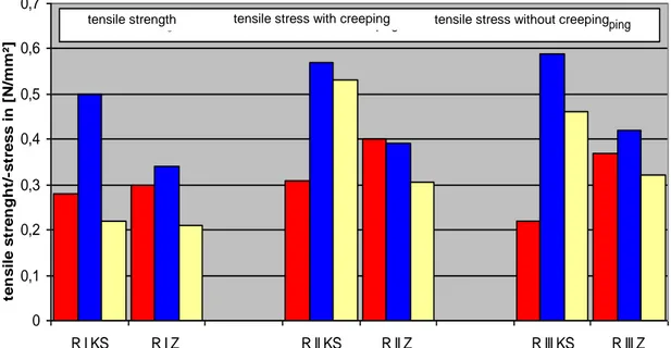
tensile strength tensile stress with creeping tensile stress witho ut creeping
Figure 5: Calculation of flank cracking of three different gypsum-lime-mortars and two different bricks
(results)
Fig. 5 shows the results of comparative calculations using the engineering model for flank failure under temperature load case ΔT=5K. In this case, the bond between three different gypsum-lime mortars and calcareous sandstone or highly absorbent bricks is considered. Once the maximum stresses exceed the measured bond strength, the flanks will fail. It is evident that the stress-reducing effect of the creep deformation of gypsum mortar has been considered in a very realistic manner. Masonry samples exposed to this temperature load case showed flank failure in the same specimens as had been forecast in the model.
3.2. Research model
For the time being no model is available that would be able to describe both heat and moisture transport, and the complex material behaviour of masonry (shrinkage, thermal strain, creep, relaxation, failure patterns) with a high degree of precision. One reason is the highly complex dependence of the material behaviour on moisture and temperature. This dependence pattern produces coupled differential equations that have so far not been solved satisfactorily with the FEM method (Van Zijl 2000).
Up to the point at which cracking starts, hygral and thermal transport can be assumed to be a process that is independent of the mechanical condition of the system. This is why a model has been developed which combines the detailed sub-models (Sperbeck 2004). Transport processes are calculated with a program based on the finite-difference method (FDM). This also provides for realistic determination of transport processes under real climatic conditions, including the effects of solar radiation and driving rain. Results of
the time-specific thermal and moisture fields are transmitted to an FEM program, which uses the material models of Rots (1997), Lourenço (1996) and Van Zijl (2000) to calculate the resultant deformations, stresses, and cracking, due regard being given to viscous and plastic material behaviour.
The research model is to serve as a basis for extensive and effective analyses before starting rehabilitation measures, while allowing the number of pre-rehabilitation tests to be reduced substantially. Quantitative determination of the deformation and stress components, sensitivity analyses etc. give more detailed insight into the possible cause of cracks. The research model also permits the moisture distribution to be assessed for the entire cross section as a function of time. So far, the model has been used to describe two-stone bodies (see Fig. 6), in which heat and moisture transport processes were still simulated separately by making use of the symmetry (see Fig. 7).
Figure 6: Geometric model and deformation conditions in the research model
Figure 7: Two-dimensional illustration for the wall cross section / Utilization of symmetries
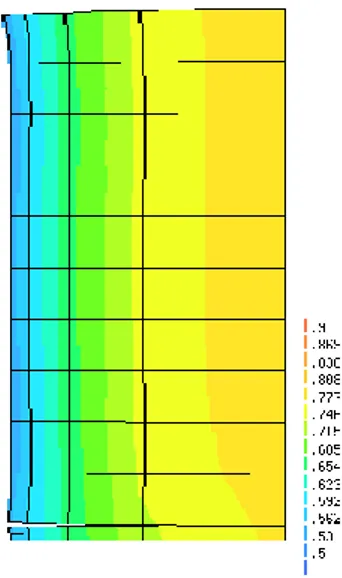
Figs. 8 and 9 show the results of moisture distribution, stress distribution and deformations for a two-stone body when dried for 100 days (initial situation: masonry with 90 % rel. air humidity; air with 50 % rel. air humidity). The expected cracking pattern as a result of the high dryness could be approximated with a high degree of precision, which is what measurements during test programmes cannot achieve. Another advantage is that climatic conditions can be simulated at random and that the numerical model can be used for probabilistic analyses. In this way it can also be determined under what conditions the bond between mortar and stone is particularly likely to fail.
Figure 8: Moisture content and deformation pattern across the cross section
Figure 9: Detail stone-joint: resulting stress in y-direction and deformation pattern
CONCLUSIONS
The simple engineering model offers a tool that permits the likelihood of cracks in new joints to be assessed in a realistic manner. There is good agreement between the results calculated with the engineering model and the results of experimental tests. On the whole, the cracking pattern was forecast correctly. First coupled calculations using the more complex research model also produce plausible results. Model development aims at providing an instrument that permits a better understanding of the failure mechanisms in the bond between natural stone and mortar joint. More broadly based experiments are essential for verification of both models.
REFERENCES
[1] Lourenço, P.B. 1996. Dissertation. Computational strategies for masonry strictures. Delft University of Technology, Netherlands
[2] Rots, J.G. 1997. Structural Masonry: An Experimental/Numerical Basis for Practical Design Rules., Rotterdam, Netherlands. Balkema
[3] Schmidt-Döhl, F. and Rostàsy, F.S. 2000 Abschlussbericht. Ingenieurmodell zur Dauerhaftigkeit des Verbundsystems Naturstein/Mörtelfuge mit Bezug auf die Neuverfugung historischen Mauerwerks. iBMB, TU Braunschweig
[4] Van Zijl, G.P.A.G. 2000. Computational Modelling of Masonry Creep and Shrinkage. Meinema BV, Delft, Netherlands