Real-time color holographic video display system
Tam metin
Şekil
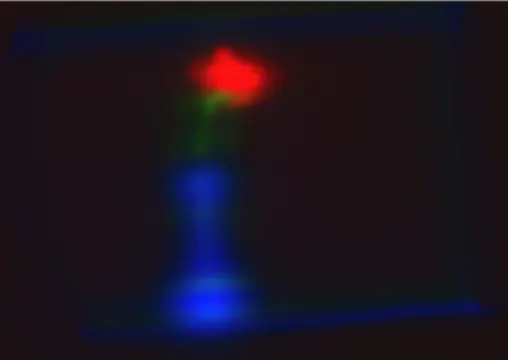
![graphic reconstructions might degrade due to low coherence characteristics. Three different color LEDs are used with three phase-only SLMs to have full color holographic reconstruc-tion [17, 18].](https://thumb-eu.123doks.com/thumbv2/9libnet/5985803.125583/2.892.528.781.108.458/graphic-reconstructions-degrade-coherence-characteristics-different-holographic-reconstruc.webp)
Benzer Belgeler
4.1.2. The 22"‘‘ congress was very significant in that the change in the election of the Party Assembly system adopted then allowed the ossified disputes to
Yine bu diferansiyel denklem seti etkileşim potansiyelinin sıfır olduğu durum için, iki farklı başlık altında, özel durum kısıtlamaları ile çözümler bulunmuş ve
calculatedabsolute photonic band gaps for oval hollow aniso- tropic tellurium (Te) rods and square hollow anisotropic Te rods for the triangular and the square lattice
In the HCC cell lines and liver tissues, ROBO1, ROBO2, SLIT1, and ROBO4, SLIT2, SLIT3 showed coordinate expression as two distinct modules, yet displayed high variability at
Participants (n = 305) filled out a questionnaire that consisted of the Zimbardo Time Perspective Inventory (ZTPI), Basic Psychological Needs (BPN), Autonomous-Related Self (ARS),
remarkable share in trade, were, paper products, chemicals, iron and steel, non-ferrous metals and glass. Chemicals, non-ferrous metals and paper products could not
This study investigates the presence of the Daylight Saving Time change effects on stock returns and on stock volatility using an EGARCH specification to model
