2D Anisotropic Photonic Crystals of Hollow Semiconductor Nanorod
with Liquid Crystals
Filiz Karaomerlioglu
1,a, Sevket Simsek
2,b, Amirullah M. Mamedov
2,c,
Ekmel Ozbay
2,d1
Department of Electronic and Computer Education, Mersin University, Mersin, Turkey
2
Nanotechnology Research Center (NANOTAM), Bilkent University 06800, Ankara, Turkey
a
[email protected], [email protected], [email protected], [email protected]
Keywords: Anisotropic Photonic Crystal, Semiconductor, Liquid Crystal
Abstract. Photonic crystals (PCs) have many applications in order to control light-wave propaga-tion. A novel type of two-dimensional anisotropic PC is investigated band gap and optical properties as a hollow semiconductor nanorod with nematicliquid crystals (LC). The PC structure composed of an anisotropic nematicLC in semiconductor square hollow nanorod is designed using the plane wave expansion (PWE) method and finite-difference time-domain (FDTD) method. It has been used 5CB (4-pentyl-4`-cyanobiphenyl) as LC core, and Tellurium (Te) as square hollow nanorod material.The PC with hollow Tenanorod with nematicLC is compared with the PC with solid Ten-anorodand the PC with hollow Tenanorod.
Introduction
Progress in solid-state physics, optics of spatially structures, and nanotechnologies based on a varie-ty of the physical and chemical processes has strongly stimulated and motivated the investigation into the properties of photonic crystals and resultedin the growth of applications of photonic band-gap materials, i.e. artificially structured materials where optical parameters are periodically modu-lated in space with a period of a unit photonic crystal cell on the order of the optical wave-length.Previous studies about photonic band-gap structures (PBG), photonic band-gap materials, and photonic crystals (PCs) are important investigations [1,2]. The basic feature of PCs is the pres-ence of permitted and forbidden frequency bands for light. It is possible to manipulate the light with PCs. Due to this property, PCs hold a great potential for designing new optical devices. There has been an increase in researches of tuning the optical properties of photonic band gap to design devic-es. Some tunable photonic band gap researches have been done in one-dimensional (1D) [3] and two dimensional (2D) [4-11] and 3D [12] PCs.
Materials are very important to determine the optical properties of a PC. The properties of PCs made of anisotropic materials different from those of isotropic PCs. Zabel and Stroud have been reported that the anisotropy of materials can split degenerate bands and this will close band gap of the PC [13]. Li et all. haveproved that the band gap can be increased by using the anisotropic mate-rials in a PC [14].B. Rezaei and M. Kalafianalyzed the tunability of full band gap of anisotropic tellurium rods infiltratedwith LCs in air background [15] and 2D hexagonal PC of circular rods consisting of an inner rod and anisotropic outer shell aligned in a uniform background [16].B. Re-zaeiet. all. are studied the absolute band gap properties of 2D PCs created by square, triangular and honeycomblattices of air holes in anisotropic tellurium background by changingthe shape and orien-tation of the holes [17]. Liu showed that the absolute bandgaps can be continuously tuned in the square and triangular lattices consisting of anisotropic-dielectric cylinders by infiltrating nematicLC [18].Liu et. all. are theoretically demonstrated the tunable bandgaps in 3D anisotropic PC structure with nematic LCs [19].Pan et. all. calculatedabsolute photonic band gaps for oval hollow aniso-tropic tellurium (Te) rods and square hollow anisoaniso-tropic Te rods for the triangular and the square lattice [20].
All rights reserved. No part of contents of this paper may be reproduced or transmitted in any form or by any means without the written permission of TTP, www.ttp.net. (ID: 139.179.98.56-07/02/14,15:12:05)
In present paper, we theoretically demonstrated and developed the band gaps and optical proper-ties in 2D anisotropic PC structure with nematic LCs. PC structure and materialswereespecially selected that optical properties are changed by external effect such as an electric field, magnetic field, light, temperature etc.The investigation is achieved by controlling intensity of band gap and optical properties added different material to a certain structure.The band gap is manipulated by rotating directors of LCs under the impact of an applied electric field. It was solved Maxwell’s equations for the propagation of electromagnetic waves in a periodic arrangement of anisotropic PC with nematic LCs. Using the PWE method and FDTD method, the PC structure composed of an anisotropic LC in semiconductor square hollow nanorod is designed.
Numerical Method
The fundamentals of the PWE method and the FDTD method are based on a direct numerical solu-tion of the time-dependent Maxwell’s equasolu-tions as illustrated in some articles [21-26].Generally LCs possess two kinds of dielectric constants. One is ordinary dielectric constantsεo, and the other is
extraordinary dielectric constantsεe. Light waves with electric fields perpendicular and parallel to
the director of the LC have ordinary and extraordinary refractive indices, respectively. The compo-nents of the dielectric tensor of the nematic LC are represented as [27]
= + − cos cos ∅ (1)
= = − cos sin ∅ cos ∅ (2)
= = − sin cos cos ∅ (3)
= + − cos sin ∅ (4)
= = − sin cos sin ∅ (5)
= + − sin (6) where is the tilt angle of the LC director(i.e. the angle between the LC director and the XY-plane) and ∅ is the rotation angle between the projection of the LC director on the XY-plane and the X-axis, and is the director of the LC.
On the other hand Bloch’s theorem [28] is used to expand the field in terms of plane waves since the light waves are transmitted in periodic structures, as
= ∑ ℎ ̂ ! "# ∙% (7)
where& is a wave vector in the Brillouin zone of the latticeand ̂ is the direction which is perpen-dicular tothe wave vector & + owing to the transverse character ofthe magnetic field , ∇ ∙ = 0.
2D Anisotropic PCs with LCs
A novel type of two-dimensional anisotropic PC structure composed of an anisotropic nematicLC in semiconductor square hollow nanorod with lattice constant ) = 1+, is presented. The PC struc-tures are depicted in Fig. 1. It has considered (a) anisotropic Tenanorod, (b) hollow anisotropic Tenanorod, and (c) hollow anisotropic Tenanorodof nematic LC-infilled in air background ( - = 1) for square lattice. Anisotropic Tenanorodhas two different principle refractive indices as ordinary-refractive index = 4.8 and extraordinary refractive index = 6.2. The ordinary and extraordi-nary refractive index of 5CB type (4-pentyl-4`-cyanobiphenyl) LCs are = 1.548and = 1.742, respectively. Parameters 56 and 5 denote the inner and outer length of anisotropic Tenanorods, respectively.
(a) (b) (c)
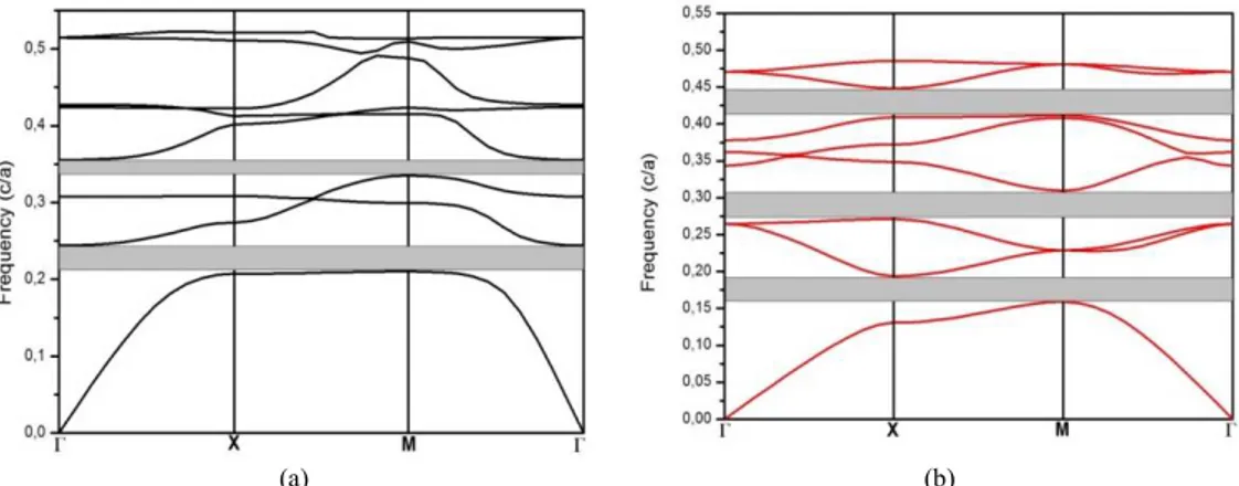
aniso-Firstly, it is considered photonic band structure for square lattice of anisotropic solid Tenano-rodin air background. It is assumed that 5 = 0.6), the sides of square nanorodparallel to the primi-tive reciprocal lattice vectors. The PBG map for TE and TM mode which is calculated along to the high symmetry point for Brillouin zone in square lattice is plotted in Fig. 2.Relative width and cen-ter normalized frequency values are seen that two band gaps for TE modes and three band gaps for TM modes as shown in Table 1.Solving for TE band polarizationit is founded TE1 band gap value from band 1 to band 2, TE2 value from band 3 to band 4. Similarly, TM1 gap sizeis 19.6 % between band 1 and band 2, TM2 is 13.3% between band 3 and band 4, and TM3 is 8.5% between band 6 and band 7 for TM band polarization.
(a) (b)
Fig. 2.Photonic band gap for (a) TE and (b) TM mode in square lattice of anisotropic Tenanorod in air back-ground.
Table 1.Photonic band gap and gap size % of TE and TM modes for square lattice of anisotropic Tenanorod in air background
TM TE
BandGap[ωa/2πc] Gap Size
% BandGap [ωa/2πc] Gap Size % TM1 (0.159-0.193) 19.6 TE1 (0.210-0.244) 14.8 TM2 (0.271-0.309) 13.3 TE2 (0.335-0.356) 5.9 TM3 (0.411-0.448) 8.5
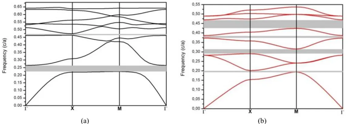
Secondly, photonic band structure of hollow anisotropic Tenanorod in air background is consid-ered. It is assumed that 56 = 0.3)and 5 = 0.6)denote the inner and outer length of hollow aniso-tropic Tenanorods.The band diagram for the second pattern is plotted in Fig. 3. When anisoaniso-tropic Tenanorodis compared with hollow anisotropic Tenanorod,it is seen that variation of band gap-number for TE mode is decreased and for TM mode is increased. Table 2 shows relative width and center normalized frequency values of hollow anisotropic Tenanorod in air background.
(a) (b)
Fig. 3.Photonic band gap for (a) TE and (b) TM mode in square lattice of hollow anisotropic Tenanorod in air background.
Table 2.Photonic band gap and gap size % of TE and TM modes for square lattice of hollow anisotropic Ten-anorod in air background
TM TE
BandGap[ωa/2πc] Gap Size
% BandGap [ωa/2πc] Gap Size % TM1 (0.196-0.202) 2.9 TE1 (0.225-0.267) 16.9 TM2 (0.291-0.315) 7.9 TM3 (0.373-0.386) 3.5 TM4 (0.424-0.474) 11.2
Fig. 4 indicates thephotonic band structure of hollow anisotropic Tenanorod of nematic LC-infiltrated in air background for square lattice. For TE and TM modes band gap sizeof hollow aniso-tropic Tenanorod of nematic LC- infiltrated approximately is closed of hollow anisoaniso-tropic Tenano-rod as shown in Table 3. Compared hollow anisotropic TenanoTenano-rod of nematic LC-infiltrated in air background with hollow anisotropic Tenanorod in air background, it can be seen that band gap number increase in TE mode, and band gap number is the same in TM mode but band gap values are changed.
(a) (b)
Fig. 4.Photonic band gap for (a) TE and (b) TM mode in square lattice of hollow anisotropic Tenanorod of nematic LC-infiltrated in air background.
Table 3. Photonic band gap and gap size % of TE and TM modes for square lattice of hollow anisotropic Tenanorodof nematic LC-infiltrated in air background
TM TE
BandGap[ωa/2πc] Gap Size
% BandGap [ωa/2πc] Gap Size % TM1 (0.193-0.201) 4.0 TE1 (0.224-0.265) 16.8 TM2 (0.290-0.315) 8.2 TE2 (0.463-0.473) 2.2 TM3 (0.372-0.386) 3.5 TM4 (0.423-0.469) 10.2
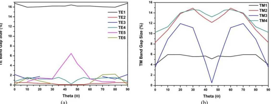
It is well known that anisotropic nanostructuring PBG structure array are capable of changing the polarization state of transmitted or reflected light. Therefore we also calculated optical response of PBG structure for different rotation angle of the polarization ellipse and ellipticity of light transmit-ted through PBG array.Thenumerical results of variation of full band gap by changing the director of LC for photonic crystal structure rotated fully from 0° to90° presents in Tables 4-5 and Fig. 5.Variation of band gap size % as a function of is demonstratedfor TE mode and TM mode in square lattice of hollow anisotropic Tenanorod of nematic LC-infiltrated in air backgroundshow that TE mode is not affected excessively from rotated photonic crystal structure (Fig. 5 (a)). The most widely gap affectingTE band structures arebetween 30°and 60°. Particularly, while TE5 band gap is reached maximum value, TE2, TE4 and TE6 band gaps are closedat = 45°.On the other hand, Fig. 5 (b) is indicated thatTM band structures are moredelicateto rotate angleof photoniccrystal
struc-ture.The most important pointat = 45°unlike TE band gaps, TM band gaps reach to the minimum value. Furthermore, TM1 band gap which has the lowest frequency in TM mode are not altered via rotate angle.
(a) (b)
Fig. 5.Variation of bandgap size as a function of for (a) TE and (b) TM mode in square lattice of hollow anisotropic Tenanorod of nematic LC-infiltrated in air background.
Table 4.Variation of full band gap size for TE modes in square lattice of LC-infiltrated anisotropic tellurium nanorodin air background.
TE1 TE2 TE3 TE4 TE5 TE6
θ0 BandGap [ωa/2πc] Gap Size % BandGap [ωa/2πc] Gap Size % BandGap [ωa/2πc] Gap Size % BandGap [ωa/2πc] Gap Size % BandGap [ωa/2πc] Gap Size % BandGap [ωa/2πc] Gap Size % 0 (0.224-0.265) 16.77 (0.423-0.425) 0.52 (0.463-0.473) 2.17 (0.522-0.525) 0.75 (0.590-0.591) 0.07 (0.634-0.638) 0.72 10 (0.231-0.271) 15.97 (0.438-0.440) 0.51 (0.481-0.487) 1.25 (0.535-0.543) 1.58 (0.567-0.571) 0.72 (0.602-0.611) 1.47 20 (0.231-0.271) 16.04 (0.444-0.446) 0.33 (0.487-0.496) 1.77 (0.538-0.545) 1.25 (0.567-0.576) 1.47 (0.614-0.619) 0.85 30 (0.229-0.270) 16.21 (0.449-0.451) 0.31 - - (0.534-0.540) 1.23 (0.567-0.574) 1.28 (0.621-0.623) 0.28 35 (0.230-0.271) 16.21 (0.454-0.455) 0.10 - - (0.536-0.545) 1.59 (0.569-0.586) 3.08 - - 40 (0.230-0.271) 16.17 (0.454-0.455) 0.09 - - (0.537-0.542) 1.07 (0.565-0.593) 4.79 - - 45 (0.225-0.266) 16.42 (0.445-0.446) 0.09 - - (0.525-0.527) 0.22 (0.549-0.586) 6.49 - - 50 (0.230-0.271) 16.17 (0.454-0.455) 0.09 - - (0.537-0.542) 1.07 (0.565-0.591) 4.36 - - 55 (0.230-0.271) 16.21 (0.454-0.455) 0.10 - - (0.536-0.545) 1.59 (0.569-0.586) 3.08 - - 60 (0.229-0.270) 16.21 (0.449-0.451) 0.31 - - (0.534-0.540) 1.23 (0.567-0.574) 1.28 (0.621-0.624) 0.44 70 (0.231-0.271) 16.04 (0.444-0.446) 0.33 (0.487-0.496) 1.77 (0.537-0.545) 1.46 (0.569-0.572) 0.68 (0.612-0.625) 2.13 80 (0.231-0.271) 15.97 (0.438-0.440) 0.51 (0.481-0.487) 1.25 (0.535-0.543) 1.58 (0.567-0.571) 0.72 (0.602-0.616) 2.24 90 (0.224-0.265) 16.77 (0.423-0.425) 0.52 (0.463-0.473) 2.17 (0.522-0.525) 0.75 (0.590-0.591) 0.07 (0.634-0.638) 0.72
Table 5.Variation of full band gap size for TM modes in square lattice of LC-infiltrated anisotropic tellurium nanorodin air background.
TM1 TM2 TM3 TM4 θ0 BandGap[ωa/2πc] Gap Size % BandGap[ωa/2πc] Gap Size % BandGap[ωa/2πc] Gap Size % BandGap[ωa/2πc] Gap Size % 0 (0.193-0.201) 4.02 (0.290-0.315) 8.29 (0.372-0.386) 3.54 (0.423-0.469) 10.25 10 (0.195-0.207) 5.95 (0.295-0.328) 10.71 (0.370-0.405) 8.92 (0.431-0.483) 11.32 20 (0.196-0.208) 5.94 (0.297-0.341) 13.84 (0.367-0.414) 11.94 (0.425-0.489) 13.99 30 (0.197-0.209) 5.58 (0.297-0.345) 14.91 (0.368-0.411) 11.14 (0.423-0.490) 14.64 35 (0.197-0.209) 5.58 (0.298-0.343) 13.79 (0.374-0.405) 7.88 (0.424-0.490) 14.52
40 (0.197-0.208) 5.69 (0.299-0.340) 12.90 (0.381-0.398) 4.43 (0.426-0.489) 13.79 45 (0.195-0.205) 5.13 (0.295-0.334) 12.15 (0.384-0.386) 0.51 (0.421-0.480) 13.23 50 (0.197-0.208) 5.69 (0.299-0.340) 12.90 (0.381-0.398) 4.43 (0.426-0.489) 13.79 55 (0.198-0.208) 5.58 (0.298-0.343) 13.79 (0.374-0.405) 7.88 (0.424-0.490) 14.52 60 (0.197-0.209) 5.58 (0.297-0.208) 14.91 (0.368-0.411) 11.14 (0.423-0.490) 14.64 70 (0.196-0.208) 5.94 (0.297-0.341) 13.84 (0.367-0.414) 11.94 (0.425-0.489) 13.99 80 (0.195-0.207) 5.95 (0.295-0.328) 10.71 (0.370-0.405) 8.92 (0.431-0.483) 11.32 90 (0.193-0.201) 4.02 (0.290-0.315) 8.29 (0.372-0.386) 3.54 (0.423-0.469) 10.25
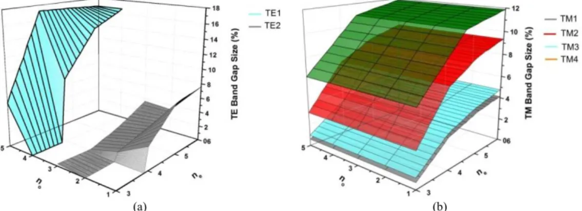
Fig. 6 is shown as variation of TE bandgap size and TM bandgap size as a function of and forsquarelattice of hollow anisotropic Tenanorod of nematic LC-infiltrated in air background. As seen in Fig. 6 (a) there exist two photonic band gaps in TE band structure. It is clear that TE1 band gap size is more sensitive than TE2 band gap size to anisotropic refractive index. TE2 band gap quite is low for < 4and < 2. Moreover, the variation of is more influenced TE1 band gap than . On the other hand, TE1 band gap is close to zero for ≤ 4and ≤ 4. It can be seen from Fig. 6 (b) that TM band structure ofsquarelattice of hollow anisotropic Tenanorod of nematic LC-infiltrated have fully four band gaps (TM1, TM2, TM3 and TM4). The variation of this band gaps according to anisotropic refractive index are similar to each other. In contrast TE band gap size, it is seen in Fig. 6 (b) that TM band gap size is linearly depended on anisotropic refractive index.
(a) (b)
Fig. 6.Variation of TE band gap size and TM band gap size as a function of ne and no for square lattice of
hollow anisotropic Tenanorod of nematic LC-infiltrated in air background. Conclusion
It was theoretically studied the optical properties in 2D anisotropic PC structure modulated byne-matic LCs. The investigation was achieved by selecting convenient structure and materials.The PC structure consisted of an anisotropic nematicLC (5CB) in semiconductor (Te) square hollow nano-rod is designed using the PWE method and the FDTD method.Numerical results were shown that optical properties of the photonic structure can be controlled by rotating directors of LC.When pho-tonic crystal structure rotated fully from 0°to 90°, absolute band gap existed between 40° and 50°. References
[1] E. Yablonovitch, J. Opt. Soc. Am. B Vol. 10 (1993), p. 283.
[2] J.N. Winn, R.D. Meade, J.D. Joannopoulos, J. Mod. Optics Vol. 41 (1994), p. 257.
[3] G. Alagappan, X. W. Sun, P. Shum, M. B. Yu, M. T. Doan, J. Opt. Soc. Am. B Vol. 23 (2006), p. 159.
[4] C.S. Kee, H. Lim, Phys. Rev.B Vol. 64 (2001), p. 121103-1.
[5] S.M. Hsu, M.M. Chen, H.C. Chang, Opt. Express Vol. 15 (2007), p. 5416.
[6] C. Schuller, F. Klopf, J.P. Reithmaier, M. Kamp, A. Forchel, Appl. Phys. Lett. Vol. 82 (2003), p. 2767.
[7] D. Liu, Y. Gao, D. Gao, X. Han, Optics Commun. Vol. 285 (2012), p. 1988. [8] N. Zhu, J. Wang, C. Cheng, X. Yan, Optik Vol. 124 (2013), p. 309.
[9] Z.Y. Li, B.Y. Gu, G.Z. Yang, Phy. Rev. Lett. Vol. 81 (1998), p. 2574. [10] H. Takeda, K. Yoshino, Phy. Lett. E Vol. 70 (2004), p. 026601-1.
[11] G. Alagappan, X. W. Sun, P. Shum, M. B. Yu, D. den Engelsen, J. Opt. Soc. Am. A Vol. 23 (2006), p. 2002.
[12] K. M. Ho, C. T. Chan, C. M. Soukoulis, Phys. Rev. Lett. Vol. 65 (1990), p. 3152. [13] I. H. H. Zabel, D. Stroud, Phys. Rev. B Vol. 48 (1993), p. 5004.
[14] Z. Y. Li, J. Wang, B.Y. Gu, Phys. Rev. B Vol. 58 (1998), p. 3721. [15] B. Rezaei, M. Kalafi, Optics Commun. Vol. 282 (2009), p. 1584. [16] B. Rezaei, M. Kalafi, Optics Commun. Vol. 266 (2006), p. 159.
[17] B. Rezaei, T. F. Khalkhali, A. S. Vala, M. Kalafi, Optics Commun. Vol. 282 (2009), p. 2861. [18] C.-Y. Liu, Phy. Lett. A Vol. 372 (2008), p. 5198.
[19] C.-Y. Liu, Y.-T.Peng, J.-Z.Wang, L.-W. Chen, Physica B Vol. 388 (2007), p. 124. [20] T. Pan, F. Zhuang, Z. Y. Li, Solid State Commun. Vol. 129 (2004), p. 501.
[21] C.Y. Liu, L.W. Chen, IEEE Photonics Techn. Lett. Vol. 16 (2004), p. 1849. [22] C.Y. Liu, L.W. Chen, J. of Nanomaterials Vol. 2006 (2006), p. 1.
[23] A. Taflove, in: Advances in Computational Electrodynamics: The Finite-Difference Time-Domain Method, chapter, 1, Artech House, Boston, Mass, USA, (1998).
[24] Z. Ma, K. Ogusu, , Optics Commun. Vol. 282 (2009), p. 1322. [25] M. Plihal, A. A. Maradudin, Phys. Rev. B Vol. 44 (1991), p. 8565.
[26] J.D. Joannopoulos, R.D. Meade, J.N. Winn, in: Photonic Crystals: Molding the Flow of Light, chapter, 2, second ed., Princeton University Press, Princeton, NJ, (1995).
[27] I.-C. Khoo, S.-T. Wu, in: Optics and Nonlinear Optics of Liquid Crystals, chapter, 2,World Scientific, Singapore, (1993).
2D Anisotropic Photonic Crystals of Hollow Semiconductor Nanorod with Liquid Crystals