i
ENDOLUMINAL COILS FOR
INTERVENTIONAL MRI PROCEDURES
A THESIS
SUBMITTED TO THE DEPARTMENT OF ELECTRICAL AND ELECTRONICS ENGINEERING
AND THE INSTITUTE OF ENGINEERING AND SCIENCES OF BILKENT UNIVERSITY
IN PARTIAL FULLFILMENT OF THE REQUIREMENTS FOR THE DEGREE OF
MASTER OF SCIENCE
By
V. Nikolay Viskuşenko
September 2010
ii
I certify that I have read this thesis and that in my opinion it is fully adequate, in scope and in quality, as a thesis for the degree of Master of Science.
Prof. Dr. Ergin Atalar (Supervisor)
I certify that I have read this thesis and that in my opinion it is fully adequate, in scope and in quality, as a thesis for the degree of Master of Science.
Prof. Dr. Y. Ziya İder
I certify that I have read this thesis and that in my opinion it is fully adequate, in scope and in quality, as a thesis for the degree of Master of Science.
Prof. Dr. A. Muhteşem Ağıldere
Approved for the Institute of Engineering and Sciences:
Prof. Dr. Levent Onural
iii
ABSTRACT
ENDOLUMINAL COILS FOR
INTERVENTIONAL MRI PROCEDURES
V. Nikolay ViskuşenkoM.S. in Electrical and Electronics Engineering
Supervisor: Prof. Dr. Ergin Atalar
September 2010
In this study we designed endoluminal magnetic resonance imaging (MRI) coils to be used for interventional procedures under the guidance of MRI. The first coil we developed is a two-channel endocervical coil for the treatment of cervical cancer. The coil was embedded into the brachytherapy applicator without interfering with its functions. It provides magnetic resonance (MR) images of the cervix with high signal-to-noise ratio (SNR) that is required for a more accurate radiation dose calculation in the treatment of cervical cancer with high dose rate brachytherapy (HDRB). The performance of this coil was tested with phantom experiments and the results proved that the design worked properly.
Second, we developed an MRI guidewire and an MR EP catheter for the treatment of atrial fibrillation (AF). The MRI guidewire had similar mechanical properties with the common cardiovascular guidewires and it was proved successful in obtaining high SNR images of the heart. The MR EP catheter could also provide high SNR images as well as clean intracardiac electrocardiogram (IECG) signal during the MR scan. Due to the loopless antenna embedded inside both of these catheters, they could be navigated in the body under the MRI. They may be used to guide complex interventional procedures such as RF ablation. The performance of these catheters was tested and confirmed with in vitro experiments.
iv
To sum up, these two technologies can play a significant role in the treatment of cervical cancer and AF as well as contributing to the development of interventional MRI.
Keywords: MRI, endoluminal coils, endocervical coil, Atrial Fibrillation (AF). Interventional MRI, Intracardiac Electrocardiogram (IECG), High Dose Rate Brachytherapy (HDRB).
v
ÖZET
MRG PROSEDÜRLERI İÇİN VÜCUT
BOŞLUKLARINA GİREBİLEN SARGILAR
V. Nikolay Viskuşenko
Elektrik ve Elektronik Mühendisliği Yüksek Lisans
Tez Yöneticisi: Prof. Dr. Ergin Atalar
Eylül 2010
Bu tez çalışmasında MRG gözetiminde girişimsel prosedürlerin gerçekleştirilebilmesi için vücut boşluklarına girebilen sargılar üretilmiştir. İlk olarak serviks kanseri tedavisinde kullanılmak üzere iki kanallı endoservikal manyetik rezonans (MR) sargısı tasarlanmıştır. Bu sargı brakiterapi aplikatörünün içine (onun asli fonksiyonlarını etkilemeden) yerleştirilmiştir ve böylelikle yüksek doz hızlı brakitherapy yöntemi kullanılarak yapılan serviks kanseri tedavileri için yüksek çözünürlükte MR görüntüleri sağlamıştır. Bu görüntüler daha doğru radyasyon doz hesaplamalarının yapılmasında kullanılmıştır. Bu sargının performansı fantom deneyleriyle test edilmiş ve sargının doğru bir şekilde çalıştığı gösterilmiştir.
İkinci olarak, Atrial Fibrilasyon (AF) hastalığının MRG kılavuzluğunda gerçekleştirilebilmesi için MRG kılavuz teli ve MR elektrofizyoloji (EF) ölçüm kateteri geliştirilmiştir. Geliştirilen MRG kılavuz teli piyasada yaygın olarak kullanılan kardiovasküler kılavuz telleriyle benzer mekanik özellikler taşımakta ve kalbin yüksek çözünürlükte MR görüntülerinin alınmasını sağlamaktadır. Geliştirilen MR EF ölçüm kateteri MR cihazı çalışıyorken kalbin yüksek çözünürlükte görüntülenmesini ve aynı anda kalbin içinden temiz bir EKG
vi
sinyalinin elde edilebilmesini sağlamaktadır. Bu kateterlerin içine yerleştirilen sargısız anten sayesinde bu kateterler vücut içerisinde navige edilebilmektedir. Bu kateterler Radyo Frekans (RF) ablasyonu gibi karmaşık girişimsel MRG prosedürleri için de kullanılabilir. Bu kateterlerin performansları insan modeli deneyleriyle test edilmiş ve bu kateterlerin doğru bir şekilde çalıştıkları gösterilmiştir.
Özetle, bu iki yeni teknoloji serviks kanseri ve AF hastalıklarının tedavisinde önemli bir rol oynayabilir ve girişimsel MRG’nin gelişmesine katkıda bulunabilir.
Anahtar Kelimeler: MRG, vücut boşluklarına girebilen sargılar, endoserviks sargı, Atriyal Fibrilasyon (AF), Girişimsel MRG İntrakardiyak Elektrokardiyagram (İEKG), Yüksek Doz Hızlı Brakiterapi.
vii
ACKNOWLEDGEMENTS
First and foremost I offer my sincerest gratitude to my supervisor, Prof. Dr.
Ergin Atalar, who supports me in every stage of my Master’s study. Beyond
his gracious academic support, he supports me in every stage of my life being not only an excellent supervisor but also a very good friend. I attribute the level of my Master degree to his encouragement and effort, and without him I would never be able to complete this thesis. Besides all, he taught me how to be a decent man. One simply could not wish for a better or friendlier supervisor.
I owe my deepest gratitude to Aslıhan Örs, without her endless support I would never be able to finish this thesis. She supports and encourages me in my most difficult times. Her excellent English increase the quality of this thesis. It is a big pleasure to know such a fantastic person and friend who is always ready to help me. I could not thank you enough.
My grateful thanks to Mr. Sinan Kobaoğlu and the entire staff of the Ministry of Industry for providing the financial support. Without their support, it wouldn’t be possible to startup this project.
I would also like to thank Muratcan Alkan, for his endless help and support in writing my thesis. Without his amazing help I would never shape this thesis.
I would like to thank Prof. Dr. Yusuf Ziya İder and Prof. Dr. Ahmet Muhteşem Ağıldere for accepting to evaluate my thesis and to be a member of my jury.
My special thanks go to Emre Kopanoğlu for providing me academic support during my thesis. I would also like to express my sincere gratitude to Selman Özbayatlı, Volkan Açıkel, Yiğitcan Eryaman and all the technical and academic staff at the National Magnetic Resonance Research Center (UMRAM) for their great assistance and support during this project.
viii
I would like to thank all the people that contributed with their expertise and work to the realization of this research. Especially I want to thank Dr. Özcan Ertürk and all the Bayındır Hospital staff, particularly the "Radiology Department" for providing me access to the MR scanner.
My special thanks go to Dr. Oktay Algın, Doç. Dr. Çağdaş Oto and the entire staff of Ankara University Faculty of Veterinary Medicine for offering their support for the animal experiments.
Most importantly I would like to thank my mom whom I owe everything in my life. Thank you very much for believing in me whatever it was and supporting me in all stages of my life.
ix
Table of Contents
1. INTRODUCTION ... 1
2. TWO CHANNEL ENDOCERVICAL COIL FOR HIGH DOSE RATE BRACHYTHERAPY (HDRB) ... 5 2.1 INTRODUCTION ... 5 2.1.1 Cervical cancer ... 5 2.1.2 Treatment Methods ... 6 2.2 THEORY ... 8 2.2.1 Loop Coil ... 8 2.2.2 Loopless Coil ... 11
2.2.3 Combined Structure of Loop and Loopless Coils ... 13
2.3 MANUFACTURING PRINCIPLES OF TWO CHANNEL ENDOCERVICAL COIL ... 15
2.3.1 Loop Coil ... 15
2.3.1.1 CONSTRUCTION OF THE RF LOOP COIL ... 18
2.3.1.2 Electrical Circuits Design ... 19
2.3.2 Endocervical Loopless Probe ... 29
2.3.2.1 The Materials and Methods ... 30
2.3.2.2 Electronic Circuit Design ... 35
2.4 Experiment and Results ... 41
2.4.1Heat Experiments of Endocervical Loopless Probe... 42
2.4.2 Visibility Performance Testing Under the MRI ... 47
2.5 DISCUSSION ... 50
2.6 CONCLUSION ... 50
3. MRI GUIDEWIRE and MR EP CATHETER for the TREATMENT of ATRIAL FIBRILLATION (AF) ... 51 3.1 Introduction ... 51 3.2 MANUFACTURING PRINCIPLES ... 53 3.2.1 GUIDEWIRE ... 53 3.2.1.1 METHOD ... 53 3.2.1.2 MATERIALS ... 56
x
3.2.2 Combined MR EP Catheter ... 64
3.2.2.1 Materials and Methods ... 64
3.2.2.1 Electrical Circuit Design ... 67
3.3 EXPERIMENTS ... 70
3.3.1 Heating Experiments ... 70
3.3.2 Phantom imaging Experiments ... 73
Experiment results ... 74
3.3.3 ECG Recording Experiments ... 76
3.3.3.1 Simulator experiments ... 77
3.3.3.2 Animal Experiment ... 79
3.3.3.3 Noise Recording in MR Room ... 80
3.3.3.4 Analysis and Filtering of the Obtained IECG Signal ... 82
3.4 DISCUSSION ... 83
3.5 CONCLUSION ... 84
4. CONCLUSION ... 85
xi
List of Figures
Figure 1 (a) anatomical scout image obtained by a surface phased array coil (b)
projection image obtained by a loopless antenna (c-e) axial FSE images obtained without moving the imaging antenna (This image is taken from [37] with the permission of the author)
Figure 2: Axial image of a dog prostate using the flexible endourethral loop coil
and dual-coil endorectal probe. (This image was taken from [2] with the permission of the author).
Figure 2.1: An image showing organs of female reproductive system (This
image is taken from Wikipedia).
Figure 2.2: The Nucletron (Veenendaal, Netherlands) CT-MR ring applicator,
which is developed for the gynecologic brachytherapy procedures. The applicator is MR-compatible. Composite fiber tubing and plastics were used in its design to eliminate distortion on CT or MR imaging.
Figure 2.3: The left image gives a simple drawing of the field distribution of the
loop coil when it is placed in a way that its surface normal would be parallel to the static magnetic field. The right image gives a simple MR image obtained by a simple loop under the explained condition. The null region in the image could be easily observed.
Figure 2.4: A simple drawing showing the magnetic field composed dl at the
arbitrary P(x,y,z) point.
Figure 2.5: Transverse field profiles of a loop coil with a 4 cm diameter, which
is placed in a way that the surface normal of the loop would be in the static field direction. The field-of-view (FOV) of the image is 25cm x 25cm. The coronal plane is obtained 1 cm away from the center of the loop coil.
xii
Figure 2.6: a. A simple drawing of magnetic field distribution of the loopless
coil. b. MR image of the loopless antenna inside the phantom filled with saline solution.
Figure 2.7: Calculation of magnetic field of a rod, of length l lying on z axis, on
an arbitrary point P
Figure 2.8: Sensitivity map of a loopless coil in coronal plane.
Figure 2.9: a. The magnetic field distribution of combination of loop and
loopless coils. b. A simple MR image of the combined coil structure inside a phantom filled with saline solution. The ROI is the assumed place of the cervix. Loopless antenna compensates the null region of the loop coil.
Figure 2.10: a: Simulation results of a loop coil placed in such a way that its
surface normal would be parallel to the static magnetic field. b: Simulation result of loopless coil. c: simulation results of a combined structure of loop and loopless coil.
Figure 2.11: a picture of the CT-MR Loop applicator which is developed for
gynecologic brachytherapy procedures. The total length of the handle from the distal site to the loop is 20 cm.
Figure 2.12: a) A coronal X-Ray image of the Nucletron CT-MR ring
applicator. b) A coronal picture of the applicator.
Figure 2.13: a) A transversal X-Ray image of the Nucletron CT-MR ring
applicator. b) a coronal picture of the applicator.
Figure 2.14: a picture of the modified Nucletron CT-MR ring applicator. A new
groove of 1.5mm is opened for the loop coil and 4mm x 4mm x 4mm space is opened for the tuning capacitor.
Figure 2.15: A picture of the manufactured loop coil placed inside the
xiii
Figure 2.16: Left: The bazooka type balun. Right: The design of a balun circuit.
The balun is contained in a cylindrical copper box and this copper box is confined in a plastic box which helps prevent human contact to the electronic circuit.
Figure 2.17: On the left shown is the internal structure of the balun explained
above. On the right is a picture of the complete balun. Left end of the balun is connected to the MR scanner and right end to the loop coil.
Figure 2.18: Resonance curve of the balun: Impedance seen on the shunt
capacitor looking at the balun side.
Figure 2.19: Coil diagram with L-type matching and tuning circuit.
Figure 2.20: A picture of matched coil in agar solution. The coil was matched to
50 ohm and -22 gain db was observed.
Figure 2.21: A picture of the matched and tuned loop coil used inside
endocervical loop coil.
Figure 2.22: Coil diagram with decoupling capacitor in resonance with the
tunning capacitors.
Figure 2.23: Matching-tuning and decoupling circuit of the single loop
endocervical loop coil.
Figure 2.24: A plot showing the resonance curve of the decoupling circuit used
for the loop coil.
Figure 2.25: A picture of the final l structure of the Nucletron CT/MR ring
applicator with a loop coil placed inside.
Figure 2.26: A picture of the Nucletron CT-MR tandem applicator which is
developed for gynecologic brachytherapy procedures. The exact detentions of the applicator are shown in the picture. The length of the inner lumen is 29.5 cm and the diameter of the inner lumen is 2.5mm.
xiv
Figure 2.27: Endocervical Loopless probe schematic: (1) Copper Coil. (2) Inner
conductor. (3) PTFE tubing. (4) Cupper Breading Shield. (5) Polyester heatshrink tubing. (6) Balun. (7) non-magnetic ASM connector.
Figure 2.28: A picture of the solenoid distal coil used for the endocervical
loopless probe. the coil is 5.9 cm long and 1.7 mm wide .
Figure 2.29: A picture of the magnet wire that was used as an inner conductor
of the coaxial portion of the endocervical loopless probe.
Figure 2.30: A picture of the polytetrafluoroethylene tubing with 1.4 mm inner
diameter and 0.4 mm wall thickness. This medical tube is used as an isolator between the inner and outer shells of the coaxial portion.
Figure 2.31: A picture of the copper breading tube with 0.2 mm wall thickness
that was used as an outer conductor of the coaxial portion.
Figure 2.32: A picture of the polyester heatshrink tube with 3.35 mm outer
diameter and 0.76 mm wall size before the expansion. This heatshrink was used as an outer isolator to provide electrical shielding and liquid isolation for the endocervical loopless probe.
Figure 2.33: A picture assembled coaxial portion of the loopless antenna that
was used inside the endocervical loopless probe.
Figure 2.34: On the left hand side the internal structure of the explained balun is
depicted. On the right side a side-view of the complete balun is given.
Figure 2.35: Simple circuit configuration of the loopless probe showing
measurement location of the reflection coefficient.
Figure 2.36: Detailed design of the decoupling circuit of the loopless probe of
endocervical MRI probe. The decoupling circuit is achieved by adjusting the length of the coaxial shaped body part of the catheter to the quarter wave length and placing the PIN diode to the proximal end of the coax.
xv
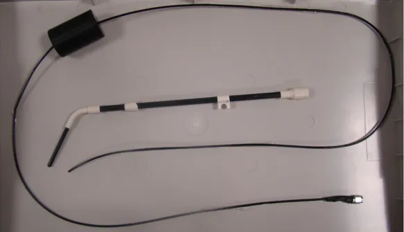
Figure 2.37: A picture of endocervical loopless probe.
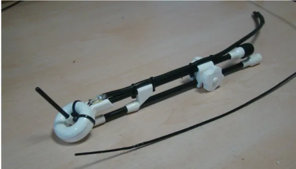
Figure 2.38: A picture of the two channel endocervix coil for HDRB
Figure 2.39: A picture of 2 channel custom preamplifier interface that was used
to test two proposed coils.
Figure 2.40: A simple drawing of the phantom gel with (Dr. Oetker Fruit
Gelatin with NaCl: 1gr/lt, CuSO4: 3gr/lt) solution that was used in the heating
experiment with endocervical loopless probe. The dimensions of the phantom are as shown in the figure.
Figure 2.41: The place of the endocervical MR probe inside the MR scanner.
(a) The position of the phantom inside the scanner. The total distance between the probe and MR wall is about 3 cm. (b) The position of the loopless probe inside the phantom. An additional reference temperature probe was used in order to measure the heat increase of the phantom.
Figure 2.42: Locations of the temperature probes on the tandem applicator
which house loopless probe.
Figure 2.43: Graphs for the temperature increase of the endocervical magnetic
resonance imaging probes.
Figure 2.44: On the left side a phantom image obtained with endocervical
loopless probe, in the middle an image obtained with loop coil and on the right side an image obtained by the two channel combined structure are given. The images were obtained 2 cm away from the ring applicator.
Figure 2.45: On the left is a picture of the empty cylindrical phantom with a
diameter of 22 cm and a length of 35 cm. The two channel endocervix coil was inserted into the kiwi and placed at the center of the phantom. On the right is the phantom filled with a copper sulphate solution (NaCl: 1gr/lt, CuSO4: 3gr/lt,
xvi
Figure 2.46: Image obtained endocervical loopless probe.T1-weighted Turbo
Spin Echo images of a kiwi submerged in a copper sulphate solution. The imaging parameters are: TR=800, TE=12, slice thickness=2.6mm, FoV=150mm x 150mm, BW=260Hz/pixel. Images were acquired using (A) with the proposed endocervical coil and (B) with a Siemens body matrix coil.
Figure 3.1: The basic design of a 0.035-inch MRI guidewire with a loopless
antenna on one end and a balun/decoupling box on the other end.
Figure 3.2: Guidewire schematic: (1) Heat-shrink tubing, (2) solenoid coil, (3)
inner conductor rode, (4) PTFE tubing, (5) nitinol hypotube.
Figure 3.3: Design of the solenoid coil for the MRI guidewire. Figure 3.4: A picture of the solenoid coil used for the guidewire.
Figure 3.5: A picture of the PTFE tubing used as an isolator between the inner
and outer conductor of the coaxial portion of the MRI guidewire.
Figure 3.6: A picture of the polyester heat-shrink tubing with 0.96 mm outer
diameter and 0.006 mm wall thickness.
Figure 3.7: A picture on the superelastic nitinol hypotube used as an outer
conductor of the MRI guidewire.
Figure 3.8: A picture of the assembled guidewire before being covered with
heat shrink.
Figure 3.9: A picture of the inner construction of the balun that was built for the
MRI guidewire.
Figure 3.10: A drawing showing the scheme of the decoupling circuit used for
the MRI guidewire.
xvii
Figure 3.12: (A) Typical structure of the common EP catheter. (B) Typical
Electrical structure of the common EP catheter.
Figure 3.13: A simple drawing showing the dimensions of the MR EP catheter. Figure 3.14: A detailed design of distal end of the MR EP catheter.
Figure 3.15: A schematic diagram of the connection diagram of the EP MR
catheter. The MR Signal is decoupled matched and connected to the balun and the transferred to the MR scanner. The leads carrying the IECG signal are directly connected to the SMA connector at the proximal end of the catheter
Figure 3.16: The electrical diagram of the five stages LPF. Figure 3.17: Frequency response of the 5 stages LPF. Figure 3.18: A picture of the proposed MR EP catheter.
Figure 3.18: The placement of the temperature probes on the MRI guidewire. Figure 3.19: The placement of the temperature probes on the MR EP catheter.
Figure 3.20: A temperature increase graph of the MRI Guidewire. The maximum
temperature increase was observed on channel 3.
Figure 3.21: The graph for the temperature rise of the MR EP catheter.
Figure 3.22: (a) Transversal image of the MRI guidewire inside the phantom.
(b) A sagittal image of the guidewire inside the phantom.
Figure 2.23: (a) Transversal image of the MR EP catheter inside the
semi-cylindrical phantom. (b) A sagittal image of the MR EP catheter inside the phantom.
Figure 3.24: The diagram of the experimental setup used for ECG recording
xviii
Figure 3.25: A picture of the ECG simulator which was used to test the
functionality of the complete system
Figure 3.26: a: The original signal obtained using the ECG simulator. Figure 3.27: The graph of the frequency response of the original ECG signal
obtained from ECG simulator.
Figure 3.28: ECG signal obtained using the proposed MR EP measurement
catheter. (a) The original signal. (b) The original signal filtered with LPF with 150 Hz cutoff frequency.
Figure 3.29: Experimental setup used for the noise recording during the MR
scan.
Figure 3.30: (A) The noise coupled to the MR EP catheter during the MRI. (B)
Gradient field of x axis. (C) Gradient field of y axis. (D) Gradient field of z axis.
Figure 3.31: (a) An IECG signal obtained from the rabbit heart. (b) Noise
coupled to the MR EP catheter during the MR imaging. (c) the summation of the signals given in (a) and (b). (d) The filtered version of the signal given in (c).
1
Chapter 1
1. INTRODUCTION
The Magnetic Resonance Imaging (MRI) has been regarded as one of the most preferred imaging techniques for the past 20 years. MRI relies on the fact that the hydrogen atoms (with some few other atoms having an odd mass or odd atomic number) found in the human tissues resonate under a large and uniform static magnetic field. Under this static field, the spins of the hydrogen atom aligns with the main magnetic field. The excitation with a radio-frequency (RF) pulse disturbs the alignment of the spins and they return to their original position by precessing about the axis of the main magnetic field. During this process, they emit an RF signal at a certain frequency called Larmor frequency. Using an RF receiver coil, the MRI instrument receives this signal and then converts it to an MR image. Therefore, the quality of the MR image is strictly dependent on the performance of the RF coil.
MRI has a lot of advantages over the other imaging modalities. It provides high quality soft tissue contrast and thus it is especially beneficial for the visualization of brain, cardiovascular and cancer tissue imaging. The MRI also doesn’t have any known permanent side effects on the patients and the physicians, since image acquisition by the MRI does not involve ionizing radiation.
The advantages of the MRI make it a promising technology for image guided interventional procedures. Although today usage of MRI in guiding interventional procedures (this is called interventional MRI) is uncommon in clinical practice, its popularity is expected increase in the near future. Interventional MRI enables accurate navigation and image guidance during the minimally invasive operations. Hence, with the advancements in the interventional MRI technology, the surgeons will be able to conduct very
2
difficult surgical operations with the visual help of the MRI. With accurate navigation, the surgical instruments can be delivered safely into the deep locations of the body; and with the image guidance, lesions can be safely removed (ablated) without harming healthy tissues. One of the current problems in the interventional MRI is to accurately localize surgical or treatment devices such as catheters or radioactive leads inside the body. Different studies have been conducted to address this issue.
In 1997, Ocali and Atalar used a loopless antenna based cardiovascular coil for navigation of the catheter inside the arterial vessels [1]. This catheter antenna is essentially a dipole antenna, which is a coaxial cable with extended inner conductor. The design of this structure makes it possible to construct the antenna with a very small diameter. Its electrical circuitry was placed outside the blood vessels without any performance loss. Images of the abdominal aorta of a canine, obtained by a loopless antenna are shown in Figure 1. This catheter provides high SNR images of the local region in the cardiovascular system, which can also be used to guide the electrophysiological procedures by imaging the ablation lesions.
3
Figure 3 (a) anatomical scout image obtained by a surface phased array coil (b)
projection image obtained by a loopless antenna (c-e) axial FSE images obtained without moving the imaging antenna (This image is taken from [37] with the permission of the author)
In 2004, Susil et al., developed an interventional MRI technique for high-dose-rate prostate brachytherapy and needle biopsy in a conventional MRI scanner. The device allowed taking a biopsy sample from specific sites within the prostate that were accurately registered with the MR image data. And at the same time, it provided accurate MR-image guided placement of brachytherapy treatment catheters.
Although interventional MRI coils could be used alone, they can also be used in combination with other internal or external coils. In 2003, Yung [2] used four channel arrays, one as a surface coil, two as endorectal coils and one as a flexible endourethral coil for the MRI of canine prostate. Figure 2 shows an imaging of the canine prostate obtained by 4 channel phased array coils.
4
Figure 4: Axial image of a dog prostate using the flexible endourethral loop coil
and dual-coil endorectal probe. (This image was taken from [2] with the permission of the author).
In this study we developed MRI coils for interventional procedures to be used in the treatment of cervical cancer and atrial fibrillation (AF). These two common diseases pose some challenges in the process of treatment. In case of cervical cancer treatment with HDR brachytherapy, accurate radiation dose calculation is only possible with precise visualization of the tumors. Currently available imaging techniques do not provide sufficient imaging quality for this procedure. To this end, we developed a two channel endocervical coil, which could be embedded into the brachytherapy applicator without interfering with its function and provide high quality MR images for accurate radiation dose calculation Moreover, since the images are obtained while the applicator is in place, the inaccuracies caused by the replacement of the tumor during the insertion of the applicator is eliminated. In case of the AF treatment, X-Ray fluoroscopy guided ablation is the most prevalent technique nowadays. However, because of the poor visualization of soft tissues, difficulties are experienced in creating linear and continuous lesions. Hence, we designed electrophysiological (EP) catheters for MRI guided procedures. The catheters not only provide high quality images but also navigate the treatment.
5
Chapter 2
2. TWO CHANNEL ENDOCERVICAL COIL
FOR HIGH DOSE RATE
BRACHYTHERAPY (HDRB)
2.1 INTRODUCTION
2.1.1 Cervical cancer
Cervical cancer is a very common disease in the developing countries despite its low incidence in Western Europe and North America [3]. Furthermore, an increase in rapidly growing tumors was noticed among young women in recent years [4]. Human papilloma virus is the major cause of the cervix cancer, which is observed in 90% of the women with the disease [5]. The most important prognostic factors of the cervical cancer are tumor size, tumor extension, and nodal involvement [6].
The cervix is located in the lower part of the uterus between the bladder and rectum and connected to the pelvic soft tissues and bones by several ligaments and muscles. The cervix has a central orifice (the external os) with an anterior and a posterior lip, and an internal orifice (isthmus) with the endocervical canal between the two (Figure 2.1). The diameter of the cervix varies from 2 to 5 cm, with a width of 2.5 to 5 cm and a thickness of 2 to 4 cm. Its length varies from 2 and 5 cm (as the length of the endocervical canal). The length of the uterine cavity varies somewhere between 4 to 10 cm [7].
The whole uterus including the cervix and the vaginal wall are densely vascularized and their tolerance to radiation is very high. In contrast, critical organs which are directly adjacent to the cervix like the rectum or the bladder are more radiosensitive. In some cases, the highly radiosensitive small and large
6
bowel (sigmoid) may be in direct contact with the uterine wall as well. The vagina must also be considered as an organ at risk [7].
Figure 2.1: An image showing organs of female reproductive system (This
image is taken from Wikipedia).
2.1.2 Treatment Methods
Depending on the stage of the disease, hysterectomy (surgical removal of the uterus and cervix), radiotherapy (radioactive source treatment) and chemotherapy (treatment of disease by chemicals) methods are used to treat cervical cancer. It is suggested to use concentrated radiotherapy such as High Dose Rate (HDR) brachytherapy if the disease has not spread to the whole body.
Brachy is Greek word for “short distance” and brachytherapy, also known as internal radiotherapy, means delivering the radiation sources inside or next to the target region. The radiation sources are placed directly or with endoluminal applicator at the site of the cancerous tumor. This placement ensures that only the localized region will be affected by the radiation and the healthy tissues are kept away from the radiation. This principle is the main advantage of brachytherapy over the external beam therapy [8,9].
7
During the application of HDR brachytherapy, radio-oncologists are interested in working with images of the cervix with as much SNR and resolution as possible, to increase the accuracy of the radiation dose planning. Computer Tomography (CT) imaging method, which is widely used nowadays, does not provide sufficient imaging quality to serve this purpose [10,11]. Even though MRI does not provide the ideal resolution for radiation dose planning, this technique provides the best imaging contrasts [12]. In a study of radiation dose calculation for the treatment of cervical cancer, images obtained from MRI and CT were compared and CT was found to show the region of treatment erroneously large [13]. Despite being more reliable than the CT image, the resolution of the MRI images does not have the optimum resolution due to the existence of external coils in MRI [14]. Furthermore, it is favorable to obtain the images of the region while the applicator is in place. Hence, we designed a two-channel RF coil, which is embedded inside a commercially available cervical applicator, enabling high resolution imaging of cervix.
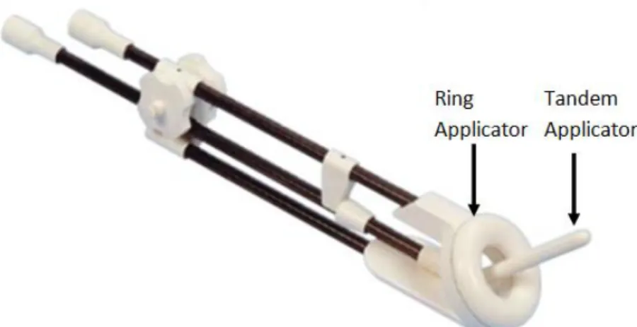
The Nucletron (Veenendaal, Netherlands) CT-MR ring applicator, which consists of a loop and a tandem applicator, is developed for the cervical brachytherapy procedure (Figure 2.2). In brachytherapy procedures, the loop applicator is located adjacent to the cervix and the tandem applicator goes through the loop into the cervix. In this study, however, the applicator was modified by placing a loop coil inside the loop applicator. A loopless coil [1] is inserted into the tandem applicator during the MRI, which can be later removed during the brachytherapy, leaving its place to the radiation source.
8
Figure 2.2: The Nucletron (Veenendaal, Netherlands) CT-MR ring applicator,
which is developed for the gynecologic brachytherapy procedures. The applicator is MR-compatible. Composite fiber tubing and plastics were used in its design to eliminate distortion on CT or MR imaging.
2.2 THEORY
2.2.1 Loop Coil
Loop coils can be used in various applications. They can be used as surface coils or they can be inserted into the vessels or body cavities if built in small diameter. The small loop coils not only enable access to the body cavities but also increase the SNR [15]. In the first step of a loop coil preparation, a loop is tuned to a desired frequency and then matched. Next, this coil is decoupled from the transmit coil via an active decoupling circuit. And finally, with the construction of a balun circuit to prevent unbalanced currents, the loop coil is ready to be used in the MRI scan.
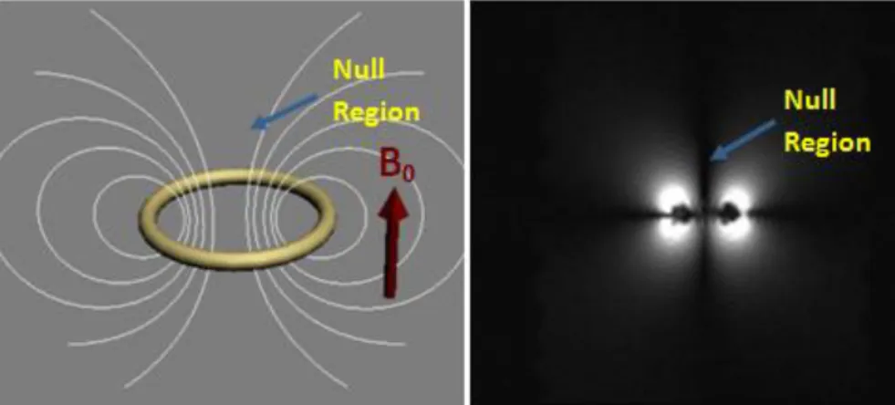
A magnetic field distribution of the loop coil is shown in Figure 2.3. Although the anatomical structure of the cervix varies from patient to patient, the most common place for the loop coil is when its surface normal is parallel to the static magnetic field. In that situation, a null region occurs in front of the loop which coincides with the region of interest. Despite this null region, however, the coil
9
provides sufficiently high SNR in the image. A small experiment was conducted in order to prove this phenomenon. In Figure 2b, the null region of the loop coil is depicted. The image at the left was obtained using a loop coil with 4cm in diameter, which is placed inside a saline solution so that surface of the coil is perpendicular to static magnetic field.
Figure 2.3: The left image gives a simple drawing of the field distribution of the
loop coil when it is placed in a way that its surface normal would be parallel to the static magnetic field. The right image gives a simple MR image obtained by a simple loop under the explained condition. The null region in the image could be easily observed.
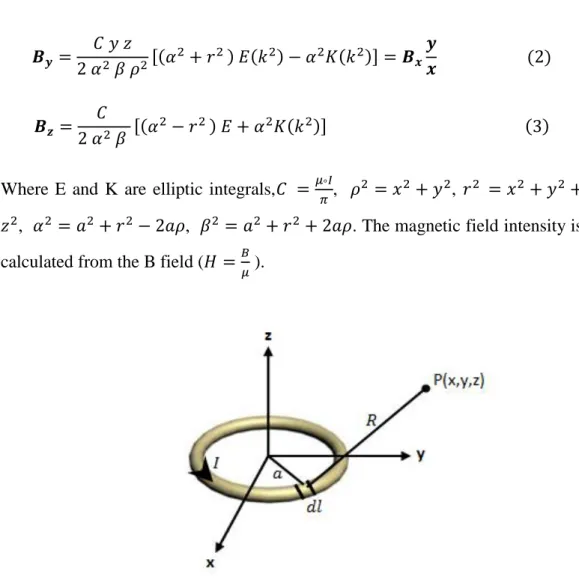
It is assumed that during the reception of the free induction decay (FID), signal induced currents on the loop has a uniform distribution along the loop. Then, the reciprocity principle was used to obtain sensitivity map of the coil [16]. A uniform current distribution assumed on the coil and magnetic field distribution was calculated. Then sensitivity map is obtained using the transverse components of the field. In Figure 2.4 a simple model problem is depicted. The magnetic field created at an arbitrary point P(x,y,z) by a differential current element with length dl, is calculated as follows [17].
10
Where E and K are elliptic integrals, , , , , . The magnetic field intensity is calculated from the B field ( ).
Figure 2.4: A simple drawing showing the magnetic field composed dl at the
arbitrary P(x,y,z) point.
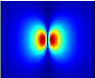
Using the calculation above, the magnetic field intensity of the loop coil with a 4 cm diameter was plotted using MatLab (MathWorks, Natick, MA). The simulation results are shown in Figure 2.5. This simulation was obtained in collaboration with Hüseyin Kılınç.
11
Figure 2.5: Transverse field profiles of a loop coil with a 4 cm diameter, which
is placed in a way that the surface normal of the loop would be in the static field direction. The field-of-view (FOV) of the image is 25cm x 25cm. The coronal plane is obtained 1 cm away from the center of the loop coil.
In Figure 2.5, there are regions with very low signal level, which make it quite hard to get a high quality image with the loop coil. Unfortunately, these areas happen to have crucial importance in the cervix imaging. A solution to overcome this problem will be suggested in the following section.
2.2.2 Loopless Coil
A loopless antenna is a coaxial cable with an extended inner conductor. Matching and active decoupling circuits are placed at the proximal end of the coaxial cable. This enables placement of loopless coils inside catheters. A loopless coil is highly sensitive to its vicinity along the catheter shaft as seen in Figure 2.6-a. Similar to the straight wire antenna (18), its sensitivity is inversely proportional to the distance from the antenna [1]. Figure 2.6-b is obtained with a loopless coil which is placed inside a saline solution in the direction of the main magnetic field. As expected, the signal intensity around the loopless coil rapidly decreases with distance as in Figure 2.6-b.
0.5 1 1.5 2 2.5 3 3.5 4 x 10⁻⁵
12
Figure 2.6: a. A simple drawing of magnetic field distribution of the loopless
coil. b. MR image of the loopless antenna inside the phantom filled with saline solution.
The structure of a loopless antenna is similar to a straight wire antenna, thus it can be modeled as a simple straight wire. Sensitivity of a loopless coil can be found in a similar way as in the previous section. Assuming a uniform current distribution along the coil, H-field is given by:
(4) where R is the distance between the observation point P(x,y,z) and incremental source length (Figure 2.7).
13
Figure 2.7: Calculation of magnetic field of a rod, of length l lying on z axis, on
an arbitrary point P
Equation 4 gives the magnetic field intensity of a simple rod everywhere. As the sensitivity is proportional to , transverse component of the magnetic field is utilized to obtain the sensitivity map as in Figure 2.8.
Figure 2.8: Sensitivity map of a loopless coil in coronal plane.
In close proximity, the loopless antenna creates a magnetic field that is strong enough to obtain high quality images. However, as the distance increases, strength of the field decreases with 1/r.
2.2.3 Combined Structure of Loop and Loopless Coils
When the axis of the loop is along the z-direction the loop coil has sufficiently high sensitivity, however, it also has an important disadvantage- a null region at the center of the loop. Since the loop center is placed parallel to the cervix, this null region coincides with the cervix wall and causes data loss. In order to collect the data in the null region a loopless coil is placed through the center of the loop coil inside the cervix and a combined structure is obtained. Figure 2.9-a depicts a simple figure that shows the magnetic field distribution of the combined structure. Figure 2.9-b gives an MR image of the combined structure in a saline phantom. It could easily be seen that the loopless antenna compensates the nullity.1 2 3 4 5 6 7 8 9 10 x 10-5
14
Figure 2.9: a. The magnetic field distribution of combination of loop and
loopless coils. b. A simple MR image of the combined coil structure inside a phantom filled with saline solution. The ROI is the assumed place of the cervix. Loopless antenna compensates the null region of the loop coil.
Figure 2.10 shows the simulation results of a combined structure. The result again shows that the loopless coil compensates the null region of the loop coil.
Figure 2.10: a: Simulation results of a loop coil placed in such a way that its
surface normal would be parallel to the static magnetic field. b: Simulation result of loopless coil. c: simulation results of a combined structure of loop and loopless coil. 1 2 3 4 5 6 x 10⁻⁵ 1 2 3 4 5 6 x 10⁻⁵ 1 2 3 4 5 6 x 10⁻⁵
15
2.3 MANUFACTURING PRINCIPLES OF TWO
CHANNEL ENDOCERVICAL COIL
2.3.1 Loop Coil
In this chapter, the production steps of a loop coil, which is manufactured for the Endocervical MRI probe, are explained. Most MRI coils have similar parts such as balun, matching-tuning and decoupling circuitry that are required for the coils to be used in an MRI scanner safely. These parts, their implementations and their functions are explained in detail in this chapter.
The design of a loop coil starts with the investigation of the loop portion of the Nucletron CT-MR ring applicator (Figure 2.11) which is developed for gynecologic brachytherapy procedures. This non-metallic applicator is designed using composite fiber tubing in order to eliminate distortions on CT or MR images. Commercially, there are 3 main versions of this applicator. The main difference between these versions is the angle of the distal end which could be 30, 45 or 60degrees. Among these three types, 60-degree version is the most widely used one. Hence, 60-degree version is studied in this thesis. The handle of the applicator is 20cm long and the outer diameter of the loop is 38 mm. During the brachytherapy procedure, the applicator is inserted into the vagina such that its surface normal is directed through the cervix canal.
Figure 2.11: a picture of the CT-MR Loop applicator which is developed for
gynecologic brachytherapy procedures. The total length of the handle from the distal site to the loop is 20 cm.
16
Before the loop coil can be designed, the inner structure of the applicator was investigated. As there were no available documents about the inner structure of the applicator, and cutting the applicator randomly was too risky because of its high price, X-Ray was used to investigate the inner structure of the applicator. It was known that the HDR groove extends through the loop portion; hence a 1 mm copper wire was inserted into the groove to make the groove more visible. The applicator was inserted into rubber gloves so that no external material will slip inside. The structure was put into a 15cm-by-15cm rectangular plastic container filled with water and X-Ray images of the structure were obtained. Figure 2.12a shows the obtained image and Figure 2.12b gives a picture of the applicator. In Figure 2.12a, the structure can be seen clearly. The width of the loop is 12mm and relying on observation we realize that there is approximately 7mm blank space between the extension of the radiation groove and the outer wall of the applicator, which is more than enough to place the loop coil. A second image of the applicator, which was transversal, was also obtained (Figure 2.13a) and a side-view picture of the applicator is given in Figure 2.13b. Using a micrometer, the thickness of the loop was measured as 15mm as is clearly seen in Figure 2.13b. The loop consists of two parts, the case and the cap. The thickness of the cap is measured to be 6mm as is shown in Figure 2.13b. By observation, we comment that the groove is approximately 6 mm away from the cap (Figure 2.13a). Hence, the groove is approximately at the intersection plane of the case and the cap. Thus, we decided to cut the loop at this plane. With the help of a CNC machine, the loop was cut into two parts.
17
Figure 2.12: a) A coronal X-Ray image of the Nucletron CT-MR ring
applicator. b) A coronal picture of the applicator.
Figure 2.13: a) A transversal X-Ray image of the Nucletron CT-MR ring
applicator. b) a coronal picture of the applicator.
After cutting the loop into two parts, a groove was carved for the coil with 1.5mm milling cutter, for which the loop coil was modeled on the applicator using AutoCad. At the distal end of the loop, a 4mm x 4mm x 4mm space was carved for the capacitor. A picture of the resulting structure is given in Figure 2.14.
18
Figure 2.14: a picture of the modified Nucletron CT-MR ring applicator. A new
groove of 1.5mm is opened for the loop coil and 4mm x 4mm x 4mm space is opened for the tuning capacitor.
2.3.1.1 CONSTRUCTION OF THE RF LOOP COIL
The RF coil was constructed from a 1mm magnet wire (Newark, Palatine, IL), which has the optimum dimensions considering the space concern caused by the physical features of the applicator. The magnet wire was placed into the groove opened earlier. As mentioned before, the cost of the applicator is very high and we have just one sample in hand. So each time during the tuning, the coil was taken out of the applicator, the capacitor soldered outside of the applicator and then the coil was placed back to the applicator to check its performance. In order to minimize the effect of this procedure on the true shape of the coil, a rigid material is preferable. The wire was placed into the groove and its ends were opened. Then the loop coil was cut in the middle (at the space for the capacitor shown in the Figure 2.14) and ATC B type nonmagnetic tuning capacitors (American Technical Ceramics, NY) were placed. The loop was tuned with two parallel capacitors as shown in Figure 2.15. A stunt matching capacitor (ATC) is placed at the proximal end of the loop. The loop coil was decoupled by placing a small transmission line printed on the PC with one end soldered to the tuning capacitor and the other end soldered with PIN diode. A 3 mm double shield coaxial cable (Suhner, Herisau, Switzerland) with a balun at the proximal
19
end was used to connect the coil to the custom made 2 channel preamplifier interface (UMRAM, Ankara, Turkey). The loop coil was connected to the 3T MR (TIMTrio, Siemens) via this interface box.
Figure 2.15: A picture of the manufactured loop coil placed inside the
Nucletron CT/MR ring applicator.
2.3.1.2 Electrical Circuits Design
BALUN (BALANCED-UNBALANCED TRANSFORMER)
Each MRI coil (including this endocervical Loop coil) should be constructed upon proving that the balun is working properly at the Larmor frequency, 123.23 MHz. When a coil is directly connected to the scanner using a coaxial cable, unbalanced currents flow at the outer conductor of the coaxial cable. The
20
unbalanced currents might have a negative effect on the functioning of the coil in different ways. They might, for example, affect the matching impedance of the circuit. As a current is flowing at the outer conductor, an external body such as the operator’s hand close to the coaxial cable, can destabilize the matching condition of the coil by changing the matching impedance. Moreover the unbalanced current might act as a small receiving antenna; therefore any portion of human body touching the coaxial cable will create an artifact on the MR image. The unbalanced currents may also increase the noise level in the system which will decrease the SNR. These negative effects of unbalanced currents can be eliminated by using a balun circuit.
The type of balun which will be used in the endocervical loop coil is similar to bazooka type baluns with some differences [19]. In a bazooka type balun, a quarter-wavelength coaxial cable is covered with a metal shield and then this shield is connected to the outer conductor of the coaxial cable at one end so that the outer shield becomes a transmission line. If the length of the transmission line is adjusted to a quarter of the wavelength, the low impedance of one end of the balun is transformed to high impedance at the other end. The balun is connected to the coil and prevents the unbalanced current flow on the outer conductor. The principle of the bazooka balun is depicted in the Figure 2.16.
Figure 2.16: Left: The bazooka type balun. Right: The design of a balun circuit.
The balun is contained in a cylindrical copper box and this copper box is confined in a plastic box which helps prevent human contact to the electronic circuit.
21
The principle of the balun used in the endocervical loop coil is very similar to a bazooka balun, except using a bazooka balun with a quarter-wavelength would be too long to use for clinical purposes. For this specific purpose, the whole bazooka balun is shrieked into a small box that is shielded by a cylindrical copper box with closed ends. Also, the coaxial cable is winded and placed inside the box. Similar to the previous method, the outer conductor is connected to the copper shield of the balun at one end. At the other end, a shunt capacitor is placed between the outer conductor and the shield of the balun. As a result, a transmission line is created with the outer conductor of the coaxial cable and the copper shield of the box in this configuration. The short circuit is transformed into inductive impedance at the outer end of the balun so this inductive impedance gets into resonance with the shunt capacitor. The following figure demonstrates this balun type.
The balun is constructed by winding a 3 mm double shielded coaxial (Suhner, Herisau, Switzerland) cable in 4 loops and placing it inside a copper cylindrical box with dimensions of 30 mm diameter and 35mm length. This copper box is housed by a cylindrical plastic box with 40mm diameter and 43 mm length. The balun is tuned using a single ATC MR compatible B type 70pF capacitor (Figure 2.17).
Figure 2.17: On the left shown is the internal structure of the balun explained
above. On the right is a picture of the complete balun. Left end of the balun is connected to the MR scanner and right end to the loop coil.
22
The impedance seen from the shunt capacitor of the balun looking at the balun side is measured using a network analyzer. The resonance curve is plotted in the next figure. The balun impedance was measured as 1.6k ohms at 123.23 MHz.
Figure 2.18: Resonance curve of the balun: Impedance seen on the shunt
capacitor looking at the balun side.
MATCHING AND TUNING OF THE COIL
A well matched and tuned coil is necessary for a desired, high SNR value. Reflections due to a large non-zero reflection coefficient seen from the coil side may increase the noise. In order to avoid reflections, the wire loop of the coil was matched and tuned to 50 Ohms at 123.23 MHz (Larmor frequency). An L-type matching circuit i.e. a series capacitor at the middle of the loop and a shunt capacitor at the right end of the loop were used. The matching and tuning were performed with these American Technical Ceramics (ATC) 700 B series porcelain and ceramic capacitors. The L type matching circuit was preferred in this project rather than the other types of matching circuits such as Pi type and T
23
type circuits, for two main reasons [20]: Firstly, the calculated capacitor values of the L type circuit are commercially available. Secondly, L type circuit is used to decouple the internal coil from the body coil by letting the shunt capacitor entering to resonance, which will be discussed later. The following figure demonstrates the L-type matching circuit.
Figure 2.19: Coil diagram with L-type matching and tuning circuit.
The following equations are taken from [38]. In order to perform the matching, the impedance of the coil loop should be determined first. The loop impedance consists of a real and an imaginary part:
(5)
The values Rcoil and Lcoil in the equation (5) were calculated experimentally. The two test capacitors, Cs and Cp were connected to the loop and the resulting input impedance Zin was observed from the network analyzer. The results can be interpreted with the following equation:
(6)
The frequency used for our experiment ( ) was the Larmor frequency (123.23 MHz for 3 Tesla). When was determined, the required and values were calculated by using the set of equations shown below:
24
(8) In this formula, is the characteristic impedance of the coaxial line, which was 50 Ohms in this case. The initial and (the shunt capacitor and the series capacitor) values were then replaced with the newly calculated capacitances. Next, the Zcoil was measured again. If the measured Zcoil value wasn’t close to 50 Ohms, Cp and Cs were calculated again with the equations (7) and (8) using the finally measured Zcoil value. This process was repeated iteratively until the coil was matched to 50 Ohms at Larmor frequency.
In this experiment, all of the measurements for matching and tuning were performed when the coil was inside an agar copper sulfate solution (Agar: 4 gr/lt, NaCl: 1gr/lt, CuSO4: 3gr/lt) phantom (Figure 2.20). This solution was
identical to the solution used for coil imaging. The load impedance of the coil in the solution medium and in the air are different from each other, therefore they require different matching-tuning circuitry. As these endocervical coils will be placed in the human body, the matching and tuning experiment should be conducted when the coil is placed inside the phantom. A plastic glove helped to isolate the coil each time.
In order to achieve the approximate conductivity of a cervix tissue (0.51 S/m), a certain amount of copper sulfate and salt was added to water which turned out to have a conductivity of 0.56 S/m. The conductivity may alter the input impedance; therefore it should be carefully determined. A picture of the matched coil is shown in Figure 2.20.
25
Figure 2.20: A picture of matched coil in agar solution. The coil was matched to
50 ohm and -22 gain db was observed.
Figure 2.21: A picture of the matched and tuned loop coil used inside
26
DECOUPLING
During the body scan, the MRI scanner sends RF pulses to adjust the spins of the body in the transmit phase. The echo caused by the recovery of the spins is listened by the scanner to create a conventional MR image. In the transmission phase, RF waves transmitted by the scanner cause some induced currents passing on a tuned and matched coil. These induced currents cause an additional magnetic field and leads to a change in the orientation of the spins in a predictable way. This results in decoupling artifacts on the MR image. To prevent this effect, the coil should be decoupled and the induction of the current in the transmission RF pulses should be eliminated. A simple decoupling mechanism was used for this purpose; a non-magnetic PIN diode (MA4P7461F-1072T, Macom, Lowell, MA) was used to put the shunt capacitor in resonance. In order to do this, a DC voltage was supplied to the coil during the transmission phase of the scanning. This DC voltage turned the PIN diode on and helped it to act almost like a short circuit. The following figure illustrates the matching and tuning capacitors and the diode placed at an L distance away from the shunt capacitor.
Figure 2.22: Coil diagram with decoupling capacitor in resonance with the
tunning capacitors.
The two lines printed on the PCB connecting the diode and the shunt capacitor can be regarded as a small two line transmission line. The impedance of the short circuit was transformed to an inductive value through this small transmission line so that this inductance value was in resonance with the shunt
27
capacitor. The state of resonance can only be reached when the shunt capacitor is in resonance with the inductance value that is caused by the diode end. This causes an increase in the impedance seen from the capacitor side, resulting in a small or no current flow through the loop coil. Finding the exact length of the transmission line is very crucial at this point. This distance was calculated with the following method; a small copper wire was used to short circuit the two lines of the transmission line. With the help of the network analyzer, the impedance seen from the capacitor end looking to diode side was measured on different locations of the wire on the transmission line. The location of the wire on the transmission line, where the maximum impedance was observed, was marked. Then this small wire was replaced with the PIN diode and the impedance was measured continuously, but this time a DC voltage of 0.8 V was supplied from the network analyzer. By the time the resonance is achieved, the decoupling diode accomplishes its task. The Figure 2.23 below shows the orientation of the matching and tuning and decoupling circuitry of the endocervical loop coil.
Figure 2.23: Matching-tuning and decoupling circuit of the single loop
endocervical loop coil.
The final appearance of the endocervical coil that is ready to be tested in an MRI scanner is shown in the Figure 2.25 .
28
Figure 2.24 shows the resonance state achieved between the shunt capacitor and the diode used for the decoupling circuit. Impedance value seen by looking from the coil end of the shunt capacitor is plotted in the figure.
Figure 2.24: A plot showing the resonance curve of the decoupling circuit used
for the loop coil
120 121 122 123 124 125 126 127 128 129 130 0 50 100 150 200 250 300 350 Frequency (Mhz) M a g n it u d e ( O h m s ) Zin = 300 Ohms at 123.23 Mhz
29
Figure 2.25: A picture of the final l structure of the Nucletron CT/MR ring
applicator with a loop coil placed inside.
2.3.2 Endocervical Loopless Probe
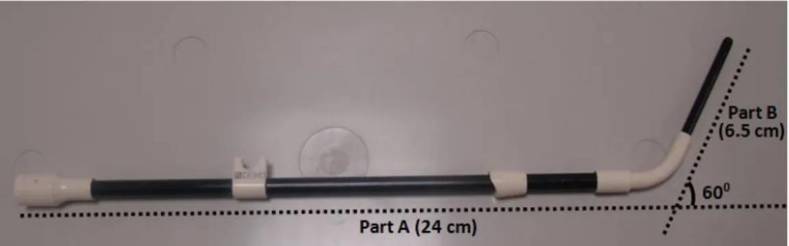
The design of an endocervical loopless probe starts with the investigation of the tandem applicator of the Nucletron CT-MR ring applicator (Figure 2.26), which was developed for gynecologic brachytherapy procedures. This non-metallic applicator is also designed using composite fiber tubing in order to eliminate distortions on CT or MR images. The 60-degree version was studied in this work (the reason was explained in the previous section). Figure 2.26 shows the described tandem applicator. The total length of the applicator is 29.5 cm. The longer part of the applicator, which is marked as part A in Figure 2.26, is 24 cm long and 6mm wide. This part is placed inside the vajina during the HDRB procedures. The shorter part, which is marked as part B in Figure 2.26, is 6.5 cm long and 3.8 mm wide. This part, on the other hand, is placed through the ring applicator into the cervical canal. The diameter of the inner lumen of the applicator is measured as 2.5 mm.
30
Figure 2.26: A picture of the Nucletron CT-MR tandem applicator which is
developed for gynecologic brachytherapy procedures. The exact detentions of the applicator are shown in the picture. The length of the inner lumen is 29.5 cm and the diameter of the inner lumen is 2.5mm.
2.3.2.1 The Materials and Methods
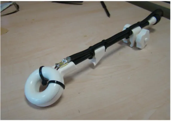
The design of the endocervical loopless probe is shown in Figure 2.27. The probe is designed in a way that it could be housed inside a brachytherapy applicator during the MRI and can be easily removed, giving its place to the radiation source. The design of the endocervical loopless probe is based on the loopless antenna design. Since it has a very small profile, it can be used in the body cavities for the purpose of acquiring high signal-to-noise ratio images in the vicinity of the region it is placed. The endocervical loopless probe consists of a coaxial cable with extended inner conductor, decoupling/ matching circuits and a balun.
The detailed design of the loopless antenna is shown in Figure 2.27. All the dimensions of the material used in the construction of the endocervical loopless probe were chosen in accordance with the tandem applicator inner lumen size of 2.5 mm. So, the loopless coil was designed to be 2.3mm in diameter and 133.2 cm in length, and was constructed using all medical-grade components. Basically, the antenna consists of a coaxial portion and an extended inner conductor. From (12) we know that the length of the inner conductor has to be adjusted to the λ/4 at Larmor frequency. However, this is unreasonable in our case as λ/4 at 123.23 MHz is longer than 30 cm. The highest signal intensity is achieved at the distal end of the coaxial portion and then decreased
31
exponentially. In that situation the cervix (ROI) would be nearly 25 cm far from the coaxial portion and the signal at this region is significantly low. In order to solve this issue, we used a 1.7 mm wide and 5.9 cm long solenoid coil (Figure 2.27-1) instead of the extended inner conductor. The proximal end of this solenoid coil was connected to the 0.4 mm cupper magnet wire (Newark, Palatine, IL) through the entire length of the endocervical loopless probe (Figure 2.27-2). This magnet wire constitutes the inner conductor of the coaxial portion. This magnet wire was inserted through a polytetrafluoroethylene (PTFE, Zeus, Orangeburg, SC) medical tubing with 1.4 mm inner diameter and 0.4 mm wall thickness. This medical tubing acts as an isolator between the inner and outer conductors of the coaxial portion (Figure 2.27-3). The whole coaxial portion was covered with flat braided tinned copper tube (Newark, Palatine, IL) which is the outer conductor of the coaxial portion (Figure2.27-4). The whole assembly including the solenoid coil was covered with polyester heatshrink tubing (Advanced Polymer, Salem, NH) with 0.076 mm wall thickness (Figure 2.27-5 ). The length of the coaxial portion was adjusted to 3λ / 4 wavelengths - 127.3 cm - at 123.23 MHz Larmor frequency. A non-magnetic SMA connector (Lemo, Ecublens, Switzerland) was placed to the proximal end of the loopless probe (Figure 2.27-7). A balun (Balance Unbalance Transformer) was placed 57 cm away from the distal end of the coaxial portion (Figure 2.27-6) and the endocervical loopless probe was matched and decoupled. These circuits are described in detail in the following sections.
32
Figure 2.27: Endocervical Loopless probe schematic: (1) Copper Coil. (2) Inner
conductor. (3) PTFE tubing. (4) Cupper Breading Shield. (5) Polyester heatshrink tubing. (6) Balun. (7) non-magnetic ASM connector.
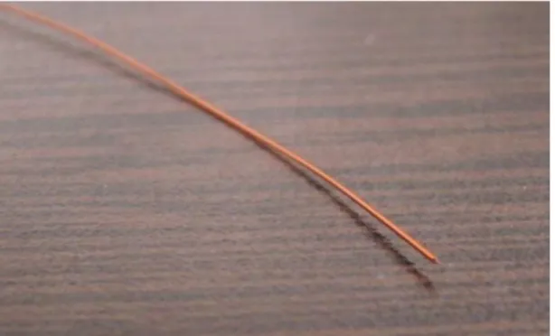
Solenoid Distal Coil
A picture of the solenoid distal coil is given in Figure 2.28. This handmade coil is made by tightly winding 0.2 mm (Newark, Palatine, IL) magnet wire around 1 mm nitinol rode. In the beginning the coil was produced 10 cm long, however the coil was then shortened to give an approximate real impedance of 50 ohms. This procedure is explained in detail in matching and tuning section. The length of the coil was adjusted to the 5.9 cm for the sample that is explained in this work.
Figure 2.28: A picture of the solenoid distal coil used for the endocervical
loopless probe. the coil is 5.9 cm long and 1.7 mm wide .
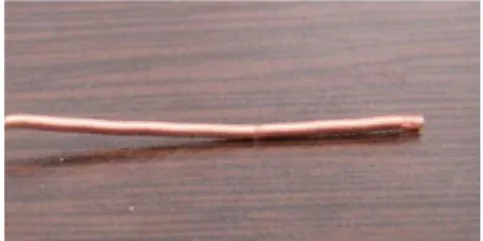
Inner Conductor of Coaxial Portion
The inner conductor for the coaxial portion is given on the Figure 2.29. A 0.4 mm copper magnet wire (Newark, Palatine, IL) was used. The diameter of the wire was determined so that the characteristic impedance of the coaxial portion would be around 50 ohms. This procedure will be described in the Matching and tuning sections.
33
Figure 2.29: A picture of the magnet wire that was used as an inner conductor
of the coaxial portion of the endocervical loopless probe.
Medical Tubing (Isolator for coaxial cable )
A polytetrafluoroethylene (PTFE, Zeus, Orangeburg, SC) medical tubing with 1.4 mm inner diameter and 0.4 mm wall thickness was used as an isolator between the inner and outer conductors of the coaxial portion.
A polytetrafluoroethylene tubing (PTFE, Zeus, Orangeburg, SC) with 1.4 mm inner and 0.4 mm wall thickness (Figure 2.30) was used to provide an isolation between the inner and outer conductor of the coaxial portion and provide circuit stability as well as providing the torque transition. PTFE has the desirable dielectric properties (ϵr=2 or less). This is especially true for high radio
frequencies, making it suitable to be used as an insulator in cables. PTFE has one of the lowest fraction values among solids. This low fraction helps us pass it through the copper breading tube (Figure 2.31) easily. The dimensions of this PTFE tube are determined so that the characteristic impedance of the coaxial portion will be around 5 ohms and at the same time the outer diameter of the coaxial portion could be kept less than 2.4 mm. A picture of the PTFE tube is given in the following figure.
34
Figure 2.30: A picture of the polytetrafluoroethylene tubing with 1.4 mm inner
diameter and 0.4 mm wall thickness. This medical tube is used as an isolator between the inner and outer shells of the coaxial portion.
Cupper Breading Tube
A picture of this copper braided tube is shown in Figure 2.31. This copper breading tube (Newark, Palatine, IL) with 0.2 mm wall thickness was used as an outer conductor of the coaxial portion. Again the dimension of the tube is determined to adjust the characteristic impedance of the coaxial portion to 50 ohm as well as the outer diameter to a value less than 2.4 mm.
Figure 2.31: A picture of the copper breading tube with 0.2 mm wall thickness
that was used as an outer conductor of the coaxial portion.
Heat Shrink
A polyester heatshrink (Advanced Polymer, Salem, NH) with 3.35 mm outer diameter and 0.76 mm wall size with ½ expansion ratio was used as an outer isolator to provide electrical shielding and liquid isolation. This heatshrink