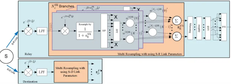
Multi-resampling Doppler compensation in cooperative underwater OFDM systems
Tam metin
Şekil

Benzer Belgeler
In this work we have presented a novel channel estimation algo- rithm for AF cooperative relay based OFDM systems in the presence of sparse underwater acoustic channels and of
Özetre - Bu bildh'ide, seyrek yapldaki sualtl akustik kanallar üzerinden 4;ab�an gü4;lendh'-ve-aktar (AF) i�birlikli röle tabanh dik frekans bölmeli 4;ogullamah
For that, we use linearly combined pulses (as suggested by the standard) that can generate notches at the desired frequencies, present coherent and noncoherent receiver structures
Second, based on the Gaussian mixture model we develop an efficient and low complexity novel algorithm by combining the MP and the SAGE techniques, called the MP-SAGE algorithm
The T-test results show significant differences between successful and unsuccessful students in the frequency of using the six categories of strategies except
41 Orijinal metin, cümlenin anlamına göre ilave ekle tamir edildi. 42 Orijinal metin, cümlenin anlamına göre ilave ekle
İngilizler güçlü merkezi bir yönetim kurabilmek maksadıyla vergi siste- mini yeniden düzenlediler. Böylelikle hem yönetimin finansmanı sağlanacaktı hem de vatanın bir
Birinci Daire: Erkân-ı Harbiye-i Bahriye Müdüriyeti İkinci Daire: Tersane-i Âmire Kumandanlığı Üçüncü Daire: Tersane-i Âmire Memuriyeti Dördüncü Daire: Mesarifat
