Multiband one-way polarization conversion in
complementary split-ring resonator based
structures by combining chirality and tunneling
Andriy E. Serebryannikov,1,2,3,* Miguel Beruete,3 Mehmet Mutlu,2,4 and Ekmel Ozbay2 1Faculty of Physics, Adam Mickiewicz University, 61-614 Poznań, Poland
2Nanotechnology Research Center - NANOTAM, Bilkent University, 06800 Ankara, Turkey 3Antennas Group - TERALAB, Department of Electrical Engineering, Universidad Pública de Navarra, 31006
Pamplona, Spain
4Geballe Laboratory for Advanced Materials, Stanford University, Stanford, California 94305, USA
Abstract: Multiband one-way polarization conversion and strong
asymmetry in transmission inspired by it are demonstrated in ultrathin sandwiched structures that comprise two twisted aperture-type arrays of complementary split-ring resonators (CSRRs), metallic mesh, and dielectric layers. The basic features of the resulting mechanism originate from the common effect of chirality and tunneling. The emphasis is put on the (nearly) perfect polarization conversion of linear incident polarization into the orthogonal one and related diodelike asymmetric transmission within multiple narrow bands. Desired polarization conversion can be obtained at several resonances for one of the two opposite incidence directions, whereas transmission is fully blocked for the other one. The resonances, at which the (nearly) perfect conversion takes place, are expected to be inherited from similar structures with parallel, i.e., not rotated CSRR arrays that do not enable chirality and, thus, polarization conversion. It is found that the basic transmission and polarization conversion features and, thus, the dominant physics are rather general, enabling efficient engineering of such structures. The lowest-frequency resonance can be obtained in structures made of conventional materials with total thickness less than λ/50 and up to ten such resonances can correspond to thickness less than λ/20.
©2015 Optical Society of America
OCIS codes: (050.6624) Subwavelength structures; (260.5740) Resonance; (120.7000)
Transmission; (050.1220) Apertures.
References and links
1. C. E. Kriegler, M. S. Rill, S. Linden, and M. Wegener, “Bianisotropic photonic metamaterials,” IEEE J. Sel. Top. Quantum Electron. 16(2), 367–375 (2010).
2. N. Liu, H. Liu, S. Zhu, and H. Giessen, “Stereometamaterials,” Nat. Photonics 3(3), 157–162 (2009).
3. V. A. Fedotov, P. L. Mladyonov, S. L. Prosvirnin, A. V. Rogacheva, Y. Chen, and N. I. Zheludev, “Asymmetric propagation of electromagnetic waves through a planar chiral structure,” Phys. Rev. Lett. 97(16), 167401 (2006). 4. C. Menzel, C. Helgert, C. Rockstuhl, E.-B. Kley, A. Tünnermann, T. Pertsch, and F. Lederer, “Asymmetric
transmission of linearly polarized light at optical metamaterials,” Phys. Rev. Lett. 104(25), 253902 (2010). 5. M. Mutlu, S. Cakmakyapan, A. E. Serebryannikov, and E. Ozbay, “One-way reciprocal spoof surface plasmons
and relevant reversible diodelike beaming,” Phys. Rev. B 87(20), 205123 (2013).
6. X. Xiong, W.-H. Sun, Y.-J. Bao, M. Wang, R.-W. Peng, C. Sun, X. Lu, J. Shao, Z.-F. Li, and N.-B. Ming, “Construction of a chiral metamaterial with a U-shaped resonator assembly,” Phys. Rev. B 81(7), 075119 (2010). 7. E. Plum, V. A. Fedotov, and N. I. Zheludev, “Planar metamaterial with transmission and reflection that depend
on the direction of incidence,” Appl. Phys. Lett. 94(13), 131901 (2009).
8. R. Singh, E. Plum, C. Menzel, C. Rockstuhl, A. K. Azad, R. A. Cheville, F. Lederer, W. Zhang, and N. I. Zheludev, “Terahertz metamaterial with asymmetric transmission,” Phys. Rev. B 80(15), 153104 (2009). 9. M. Mutlu, A. E. Akosman, A. E. Serebryannikov, and E. Ozbay, “Diodelike asymmetric transmission of linearly
polarized waves using magnetoelectric coupling and electromagnetic wave tunneling,” Phys. Rev. Lett. 108(21), 213905 (2012).
10. J. Shi, X. Liu, S. Yu, T. Vu, Z. Zhu, H. F. Ma, and T. J. Cui, “Dual-band asymmetric transmission of linear polarization in bilayered chiral metamaterial,” Appl. Phys. Lett. 102(19), 191905 (2013).
11. M. J. Lockyear, A. P. Hibbins, K. R. White, and J. R. Sambles, “One-way diffraction grating,” Phys. Rev. E Stat. Nonlin. Soft Matter Phys. 74(5), 056611 (2006).
12. A. E. Serebryannikov and A. Lakhtakia, “Wideband switchable unidirectional transmission in a photonic crystal with a periodically nonuniform pupil,” Opt. Lett. 38(17), 3279–3282 (2013).
13. S. Xu, C. Qiu, and Z. Liu, “Acoustic transmission through asymmetric grating structures made of cylinders,” J. Appl. Phys. 111(9), 094505 (2012).
14. P. Rodríguez-Ulibarri, M. Beruete, M. Navarro-Cía, and A. E. Serebryannikov, “Wideband unidirectional transmission with tunable sign-switchable refraction and deflection in nonsymmetric structures,” Phys. Rev. B
88(16), 165137 (2013).
15. A. E. Serebryannikov, A. O. Cakmak, and E. Ozbay, “Multichannel optical diode with unidirectional diffraction relevant total transmission,” Opt. Express 20(14), 14980–14990 (2012).
16. G. Dolling, C. Enkrich, M. Wegener, C. M. Soukoulis, and S. Linden, “Simultaneous negative phase and group velocity of light in a metamaterial,” Science 312(5775), 892–894 (2006).
17. C. García-Meca, J. Hurtado, J. Martí, A. Martínez, W. Dickson, and A. V. Zayats, “Low-loss multilayered metamaterial exhibiting a negative index of refraction at visible wavelengths,” Phys. Rev. Lett. 106(6), 067402 (2011).
18. M. Beruete, M. Navarro-Cía, V. Torres, and M. Sorolla, “Redshifting extraordinary transmission by simple inductance addition,” Phys. Rev. B 84(7), 075140 (2011).
19. V. Torres, R. Ortuño, P. Rodríguez-Ulibarri, A. Griol, A. Martínez, M. Navarro-Cía, M. Beruete, and M. Sorolla, “Mid-infrared plasmonic inductors: enhancing inductance with meandering lines,” Sci. Rep. 4, 3592 (2014). 20. M. Beruete, M. Navarro-Cía, I. Campillo, P. Goy, and M. Sorolla, “Quasioptical polarizer based on
self-complementary sub-wavelength hole arrays,” IEEE Microw. Wirel. Compon. Lett. 17(12), 834–836 (2007). 21. M. Beruete, M. Sorolla, M. Navarro-Cía, and I. Campillo, “Polarized left-handed extraordinary optical
transmission of subterahertz waves,” Opt. Express 15(13), 8125–8134 (2007).
22. M. Beruete, M. Navarro-Cía, F. Falcone, I. Campillo, and M. Sorolla, “Single negative birefringence in stacked spoof plasmon metasurfaces by prism experiment,” Opt. Lett. 35(5), 643–645 (2010).
23. F. Falcone, T. Lopetegi, M. A. G. Laso, J. D. Baena, J. Bonache, M. Beruete, R. Marqués, F. Martín, and M. Sorolla, “Babinet principle applied to the design of metasurfaces and metamaterials,” Phys. Rev. Lett. 93(19), 197401 (2004).
24. M. Zalkovskij, R. Malureanu, C. Kremers, D. N. Chigrin, A. Novitsky, S. Zhukovsky, P. T. Tang, P. U. Jepsen, and A. V. Lavrinenko, “Optically active Babinet planar metamaterial film for terahertz polarization
manipulation,” Laser Photonics Rev. 7(5), 810–817 (2013).
25. Y. Liu, Y. Cheng, and Z. Cheng, “A numerical parameter study of chiral metamaterial based on complementary U-shaped structure in infrared region,” Optik (Stuttg.) 125(3), 1316–1319 (2014).
26. Z. Li, K. B. Alici, E. Colak, and E. Ozbay, “Complementary chiral metamaterials with giant optical activity and negative refractive index,” Appl. Phys. Lett. 98(16), 161907 (2011).
27. D. L. Markovich, A. Andryieuski, M. Zalkovskij, R. Malureanu, and A. V. Lavrinenko, “Metamaterial polarization converter analysis: limits of performance,” Appl. Phys. B 112(2), 143–152 (2013). 28. See www.cst.com.
29. L. Zhou, W. Wen, C. T. Chan, and P. Cheng, “Electromagnetic-wave tunneling through negative-permittivity media with high magnetic fields,” Phys. Rev. Lett. 94(24), 243905 (2005).
30. B. Hou, H. Wen, Y. Leng, and W. Wen, “Electromagnetic wave transmission through subwavelength metallic meshes sandwiched between split rings,” Appl. Phys. Lett. 87(20), 201114 (2005).
31. T. Q. Li, H. Liu, T. Li, S. M. Wang, F. M. Wang, R. X. Wu, P. Chen, S. N. Zhu, and X. Zhang, “Magnetic resonance hybridization and optical activity of microwaves in a chiral metamaterial,” Appl. Phys. Lett. 92(13), 131111 (2008).
32. H. Liu, D. A. Genov, D. M. Wu, Y. M. Liu, Z. W. Liu, C. Sun, S. N. Zhu, and X. Zhang, “Magnetic plasmon hybridization and optical activity at optical frequencies in metallic nanostructures,” Phys. Rev. B 76(7), 073101 (2007).
33. J. H. Shi, H. F. Ma, W. X. Jiang, and T. J. Cui, “Multiband stereometamaterial-based polarization spectral filter,” Phys. Rev. B 86(3), 035103 (2012).
1. Introduction
Ultrathin structures based on coupled twisted arrays of open subwavelength resonators have recently become the focus of interest due to the possibility of obtaining chirality and relevant polarization manipulation [1–6]. Most of the performances suggested to date are associated with U-shaped, X-shaped, or similar resonance elements. Asymmetric transmission, a Lorentz reciprocal phenomenon, which enables strong forward-to-backward transmission contrast between the direct and opposite incidence directions, may appear at polarization conversion [3–5,7]. In fact, polarization conversion and asymmetric transmission represent two sides of the same phenomenon. The stronger polarization conversion, the stronger asymmetry in transmission may be, if the polarization state of the incident wave is kept. Since reciprocity forbids one-way transmission in two-port reciprocal systems, asymmetric transmission requires breaking of spatial inversion symmetry to obtain a system with a larger number of
ports. It can be achieved by twisting arrays of subwavelength resonators leading to a four-port system instead of two uncoupled two-port virtual systems in the original non-twisted structure. In particular, conversion of an incident linear polarization to circular polarization [3,7,8] or orthogonal linear polarization [4,9] and relevant asymmetric transmission have been demonstrated. Designs based on twisted subwavelength resonator arrays have been suggested with high-efficiency (>90%) one-way polarization conversion for both incident linear polarizations, ultimately leading to dual-band asymmetric transmission [10]. Although asymmetric transmission does not enable the same operation regimes as those typical for nonreciprocal devices, e.g., optical isolation, its potential in directional selectivity is evident.
The split-ring resonator (SRR) based structures are widely used for polarization conversion that represent twisted arrays of metallic elements, which are for instance U-shaped, on the dielectric substrate. The corresponding complementary SRRs (CSRRs) based structures should represent twisted arrays of U-shaped apertures in a metal layer. These two structures are optically related via Babinet's principle. Recently, an advanced structure based on twisted arrays of subwavelength resonance elements with 4U-type unit cells (i.e., with four U-shaped resonators per cell) and a metallic mesh working in the evanescent-wave regime has been proposed [9]. In this chiral structure, single-band diodelike asymmetric transmission has been demonstrated, with perfect conversion of the incident linear polarization into the orthogonal one for one direction of incidence and perfect reflection for the opposite one. This behavior has been reached owing to the common effect of tunneling, optimization of the axial ratio of the eigenwaves, and optimization of transmission phases of the eigenwaves that enables destructive interference in one direction and constructive interference in the other, for certain incident polarization states [9]. It is noteworthy that additional transmission channels, which are required for asymmetric transmission, can be obtained without polarization manipulation, for instance, due to higher diffraction orders [11–14]. In particular, perfect one-way conversion of the incident plane wave into a high order has been obtained [15]. Thus, asymmetric transmission is a rather general phenomenon, regardless of the nature of the transmission channels (modes) that may accept the incident wave energy. However, obtaining multiband diodelike asymmetric behavior is still considered as a challenging task.
Since asymmetric transmission inspired by polarization conversion has been obtained in various structures based on the resonator-type arrays, it also should appear but has not yet been studied in the structures based on the aperture-type, e.g., CSRR arrays. Generally, arrays of complex-shaped apertures like CSRR arrays promise a variety of devices with advanced functionality as compared to the conventional, i.e., rectangular and circular aperture arrays, which are well known from metamaterial studies [16,17]. Shaping the apertures, connecting them, or loading them with lumped, e.g., inductive elements allows a dramatic change of the transmission characteristics [18,19]. This approach has been already utilized in polarizers [20,21] and splitters [22]. Babinet's principle can be efficiently used to engineer CSRR based structures with desired properties by using results for the corresponding SRR based structures as entry point [23]. In this concern, V-shaped aperture arrays and antirod arrays suggested for polarization manipulation at terahertz frequencies should be mentioned [24]. Until now, polarization conversion in CSRR arrays has been studied much less than in SRR arrays. For example, conversion in twisted aperture-type arrays with 4U-type unit cells that do not contain a mesh and, thus, do not enable tunneling has been studied in [25]. In particular, the principal possibility of single-band conversion of linear incident polarization into circular and orthogonal linear polarization has been demonstrated. Also, twisted arrays of X-shaped apertures [26] should be mentioned, which may show chirality but have not been studied for asymmetric transmission. Some problems have particular importance for the full exploitation of the potential of thin chiral structures that are based on SRR arrays and CSRR arrays in polarization conversion and asymmetric transmission. They include but are not restricted to (i) multiband and wideband one-way polarization conversion and related asymmetry in transmission; (ii) nearly perfect transmission in one direction at polarization conversion and vanishing transmission in the opposite one, i.e., diodelike asymmetric transmission, and (iii) wideband suppression of the co-polarized transmission components. It is noteworthy that the
principal possibility of perfect polarization conversion, i.e., high-efficiency transmission with vanishing component that corresponds to the incident polarization state, has recently been demonstrated for a generalized theoretical performance, but without giving guidelines for design [27]. At the same time, one can consider the main results of [27] as a signature of some freedom in possible choice of geometry.
In this paper, we study polarization conversion and related directional selectivity in thin structures containing twisted arrays of electrically small CSRRs and a metallic mesh in the evanescent-wave regime, enabling the mechanism based on the common effect of chirality and tunneling. The main goal of this study is to demonstrate the principal possibility of multiband, nearly perfect, one-way polarization conversion and diodelike asymmetric transmission at subwavelength scale in the aperture-type structures with U-type unit cells. A comprehensive study of the effect of parameter variations will be carried out with the aim to demonstrate that the basic transmission and polarization conversion features and, hence, the dominant physics are rather general, leading to that the peculiar adjustment of the geometric and material parameters is not required. The obtained results allow one to estimate the possible extent of miniaturization and give some guidelines for design. We extend fundamentally the results of [9] by demonstrating multiband polarization conversion and wideband suppression of the co-polarized components for both linear orthogonal polarizations in the framework of the general mechanism comprising chirality and tunneling. Moreover. it will be shown that these effects can be obtained in stuctures with simpler, i.e., U-type unit cells instead of 4U-type unit cells and with aperture-type arrays instead of resonator-type arrays, compared to [9]. We will show that the choice of the array period and/or permittivity of the dielectric layers can strongly affect spectral locations and density of the polarization conversion bands. Compared to [25], the studied mechanism contains tunneling as one of the counterparts and enables multiband polarization conversion at subwavelength scale. To better understand the basic features of the resulting mechanism, the assumption of perfect electric conducting (PEC) metallic parts has been adopted. At the same time, results of comparison with the case when all metallic parts are made of copper are presented for some performances. Simulation results are obtained by using CST Microwave Studio [28].
2. Geometry and theoretical background
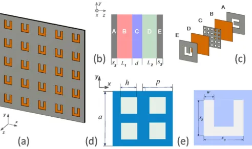
Now, let us present geometry of the structures, which are expected to properly combine the effects of chirality and tunneling and will be studied in detail in this paper. The general geometry is presented in Fig. 1. The twisted (back-side) CSRR array is identical to the original (front-side) CSRR array but rotated 90 degrees in the clockwise direction (as seen from the side of negative z toward the front-side array). The unit cell corresponds to one period in x and y directions, a=ax=ay. The metallic mesh consists of square holes with
side length h and period p=px=py where p<a. The width of CSRR slit is denoted by w ,
while s1 and s2 are the lengths of the CSRR sides, s1=s2; L1 and L2 are the thicknesses of the dielectric layers, one of which is located between the front-side CSRR array and the mesh [layer B in Figs. 1(b) and 1(c)], and the second one between the mesh and the back-side CSRR array [layer D in Figs. 1(b) and 1(c)]; d and s3 are the thicknesses of the mesh and each of the CSRR arrays. For the studied structures, we take the following geometrical parameters: p=4.4mm, h=2.2mm, L1=L2=0.25mm, d=0.5mm, s3=0.5mm,
mm 10
2 1=s =
s , w=3mm, and total thickness Δ=2(s3+L1)+d =2mm. Several structures
with twisted CSRRs will be considered, in order to demonstrate how general the observed transmission and polarization features are. They differ in the value of period a and/or permittivity of dielectric layers ε. We consider three periods: small a=13.2mm (a/p=3),
intermediate a=22mm (a/p=5), and large a=30.8mm (a/p=7), for two values of permittivity, ε=2.1 and ε=11.4. Throughout the paper, these structures are referred to as the basic configurations.
The studied structures are illuminated by a linearly polarized plane wave with electric field vector along either x - or y-axis. The case of normal incidence is considered. In the general case, a linearly polarized wave can change the polarization state when passing through a multilayer coupled system like that in Fig. 1. The complex amplitudes of the incident and transmitted waves are related to each other by the T-matrix formalism [4,9]:
= I I T T T T T T b f y b f x b f yy b f xy b f yx b f xx b f y b f x , , , , , , , , . (1)
Here, superscripts f and b indicate the forward transmission case (front-side illumination) and backward transmission case (back-side illumination), respectively. For twisted CSRR arrays like those shown in Fig. 1, we have [4,9]
T T T T T T T Txyf =− byx, yxf =− bxy, xxf = bxx= yyf = byy (2) at ε1=ε2, as dictated by Lorentz reciprocity. Our structures represent four-port reciprocal devices, whereas a Faraday rotator is a two-port nonreciprocal device, see [5].
Fig. 1. (a) Perspective view of 5×5 unit cells of the resulting thin structure seen from the back side; (b) Schematic of unit cell of the structure within one array period a=ax=ay: A - CSRR, B and D - dielectric layers with permittivity ε1 and ε2 , respectively, C - metallic mesh, E - twisted CSRR; (c) Geometry of the individual layers to be stacked within one array period, which are denoted according to plot (b); (d) Periodic metallic mesh with square holes at
h p
a=2 =4 (layer C); (e) Unit cell of CSRR array seen from the back side (layer E).
A properly designed polarization rotator can work as a one-way device, provided that the co-polarized transmission components are vanishing, while the incident wave energy is converted to one of the cross-polarized components. Simultaneously, the absence of reflections would indicate diodelike transmission, although such a device cannot work as the classical optical isolator. In the ideal case, transmission can be perfect at either the front-side or the back-side illumination, depending on which of the two incident linear polarizations is utilized, and it should vanish for the opposite-side illumination. If Tf,b=0
yy , Txyf =0, and 1
|
orthogonal one with 100% transmission efficiency will be obtained. Moreover, if the incidence direction is changed to the opposite one, while incident polarization is kept, perfect reflection should appear. This illustrates now that one-way polarization conversion leads to asymmetric transmission. In turn, if Tf,b=0
xx , Tbyx=0, and |Tyxf |=1, we obtain perfect
conversion of the x -polarized wave incident from the front side. Hence, the direction of diodelike asymmetric transmission is reversed when the incident polarization is changed to the orthogonal one, because the Lorentz reciprocity forces the scattering matrix to be symmetric.
In line with the general theory, which has initially been presented for the resonator-type array based structures in [9], the resulting mechanism in the studied aperture-type array based structures exploits chirality relevant polarization conversion and tunneling. In fact, one-way, nearly perfect polarization conversion can appear owing to the common effect of tunneling and optimization of the axial ratio of the eigenwaves and transmission phases. In the studied structures, chirality and tunneling are mainly associated with the effects exerted by the twisted CSRR arrays and the evanescent-wave metallic mesh, respectively. It is noteworthy that two mechanisms of strong transmission through the sandwiched structures, which contain a couple of SRR arrays and a mesh, have initially been suggested for the non-twisted arrays not enabling polarization conversion [29,30]. These mechanisms include tunneling by using
positive-negative-positive stacking (it is called so according to sign of permittivity of the stacked layers) and negative-index related transmission. According to [9,29], certain phase conditions must be fulfilled such that the combination of the effects exerted by the structural components, which are associated with negative-ε and positive-ε layers, may result in the perfect tunneling. To obtain it, parameters should be adjusted so that destructive interference, which is connected with the waves reflected at the interfaces of mesh, dielectric layers, and CSRR arrays, results in zero reflection. The mentioned phase conditions and destructive interference in reflections are considered as necessary conditions of perfect transmission.
This remains true regardless of whether polarization conversion and related asymmetry in transmission are possible in a certain structure. Although the arrays of resonance elements in the studied structures together with the adjacent dielectric layers are generally expected to contribute to one of the two above-mentioned mechanisms by providing either positive permittivity or negative permeability, one should take into account that it might be incorrect to separate the behavior of thin individual layers because coupling can be crucial for the performance. In our case, CSRR arrays may be strongly affected by the proximity of the mesh, so that the entire structure should be considered in order to obtain the correct equivalent parameters. Such analysis is, however, beyond the scope of the present paper, since its focus is demonstration of the principal possibility and generality of multiband one-way polarization conversion and related diodelike asymmetric transmission in aperture-type array based structures.
3. Results and discussion
3.1 Case of low-ε dielectric layers
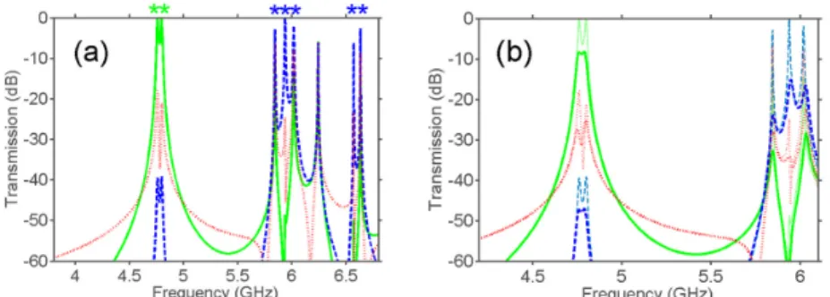
First, let us consider the structures with the small and intermediate array periods and low-ε
dielectric layers. For the small period, the peaks of |Tyxf |=|Tbxy|≈1 corresponding to perfect polarization conversion are observed in Fig. 2(a) at f =6.22GHz and f =6.39GHz. All other components of T-matrix are suppressed. Accordingly, reflections are vanishing. These features enable the desired scenario of asymmetric transmission. To quantify the observed features and check whether we stay in the subwavelength region, we obtained the following estimates at 6.2GHz: a/λ≈0.27, s1/λ≈0.2, and Δ/λ=4.09×10−2. Hence, polarization conversion and related asymmetry in transmission can be obtained in the CSRR array based structures that are at least 24 times thinner than λ. Throughout the paper, we consider high-transmission maxima, which are separated from similar maxima by dips whose depth is below the half-power level for the corresponding component of T-matrix, as transmission bands.
Such bands associated with one-way polarization conversion are denoted by asterisks in some of the figures. On the contrary to [9], where the co-polarized components were well suppressed only within a narrow frequency range, in our case suppression appears in the entire frequency range considered. For the intermediate period, |Tyxf |=|Tbxy|≈1 in Fig. 2(b) at
GHz 32 . 5
=
f and f =5.42GHz. At 5.3GHz, we obtain a/λ≈0.39, s1/λ≈0.18, and 10
54 . 3
/ = × 2
Δ λ − . Note that the value of s1/λ differs at the lowest maximum of |Tf | yx for the two considered periods, indicating that the resonances are sensitive to the coupling. On the other hand, it is clear that polarization conversion resonances, which may lead to asymmetric transmission at subwavelength scale, should not require a special procedure for parameter adjustment. It is noteworthy that the response with the twinned maxima such as in Figs. 2(a) and 2(b) is quite typical for coupled resonance structures and, in particular, for thin chiral structures. It can be explained by using the Lagrange formalism, as has been done in [2,31,32]. To compare, the insets in Figs. 2(a) and 2(b) present transmission in case when metallic parts are made of copper with conductivity σ = 5.8 × 10⁷ S/m.
Fig. 2. Transmission for basic configurations with (a) small and (b) intermediate periods at 1
. 2
=
ε ; inset in plot (a) and right inset in plot (b) present transmission in case when all metallic parts are made of copper, while results for the PEC case are repeated by using thinner lines: solid green line - |Tyxf |=|Tbxy|, dashed blue line - |Txyf |=|Tbyx|, dotted red line -
| T | | T | | T | | T | b yy f yy b xx f
xx = = = ; upper and lower left insets in plot (b) schematically show front-side and back-side view of unit cell, respectively.
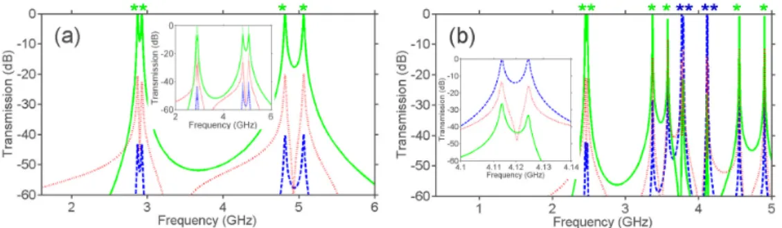
Next, let us consider the case of the large array period, see Fig. 3. Also in this case, all the basic features, which were initially observed in Fig. 2, remain. One-way polarization conversion becomes multiband and appears for both incident linear polarizations, while the lowest-frequency conversion range is downshifted. In Fig. 3(a), |Tyxf |=|Tbxy|≈1 and
0 | | |
|Txyf =Tbyx≈ at 4.76GHz and 4.8GHz. In turn, |Txyf |=|Tbyx|≈1 and |Tyxf |=|Tbxy|≈0 at GHz
94 .
5 and .57GHz6 . It is noteworthy that a/λ≈0.49, s1/λ≈0.16, and 10
18 . 3
/ = × 2
Δ λ − at 4.8GHz. Thus, only the first pair of the maxima in Fig. 3 exactly
corresponds to the subwavelength case. Comparing the values of s1/λ for the first pair of the maxima in Figs. 2(a), 2(b) and 3(a), one may expect that the peak frequencies tend to the resonance frequencies of a unit cell when a is increased, but they vary due to the changes in coupling. The presented results confirm that the dominant physics and basic transmission and polarization conversion features are quite general and remain in a wide range of the period variation. Comparison of the cases of copper and PEC metallic parts is presented in Fig. 3(b). One can see that transmission in the former case does not exceed −8.5dB for the first pair of maxima, whereas attenuation of the resonances near 6GHz is even stronger. Thus, the practical use of structures with a rather large array period can be restricted by the losses.
Fig. 3. Transmission for basic configuration with large array period (a) in the PEC case and (b) in case when metallic parts are made of copper, at ε=2.1; solid green line - |Tyxf |=|Tbxy|, dashed blue line - |Txyf |=|Tbyx|, and dotted red line - |Txxf |=|Tbxx|=|Tyyf |=|Tbyy|; in plot (b), results for the PEC case are repeated by using thinner lines.
The features observed in Fig. 3(a) indicate resonance behavior of transmission. For example,
500
>
Q for the maximum at f =5.94GHz and Q>104 for the maximum at 6.57GHz, at which |Txyf |=|Tbyx|≈1. To compare, high-Q regimes of stereometamaterial-based polarization spectral filter have been studied in [33] but without any connection to one-way polarization conversion and asymmetric transmission.
3.2 Role of chirality and tunneling
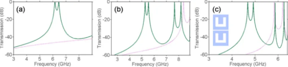
Now, let us demonstrate the possible roles of chirality and tunneling in the resulting mechanism. In line with the general theoretical framework, chirality should be brought about by the twist between two U-shaped aperture arrays, while tunneling should be chiefly brought about by the common effect of the mesh and other layers. First, we consider three structures, which differ from those in Figs. 2 and 3 in that the CSRR arrays are not twisted. Transmission results are presented in Fig. 4 for three periods from Figs. 2 and 3. For the sake of convenience, the front-side array is assumed to be identical to the back-side array translated along the z-axis, i.e., CSRRs are oriented as in Figs. 1(c) and 1(e). Two first maxima are observed between 6.2GHz and 6.5GHz in Fig. 4(a), between 5.3GHz and 5.6GHz in Fig. 4(b), and between 4.7GHz and 5GHz in Fig. 4(c). Comparing Figs. 2 and 3 with Fig. 4, we can see that rotation of one of the CSRR arrays by 90 degrees can result in a relatively weak shift of the resonance frequencies alongside the dramatic redistribution of the incident wave energy in favor of one of the cross-polarized components. Correspondingly, the polarization conversion resonances in Figs. 2 and 3 can be considered as a perturbed version of the original resonances in Fig. 4, which acquire the ability of polarization conversion due to rotation of one of the CSRR arrays. Thus, the role of twisting and related chirality is clearly seen. Since neither chirality nor polarization conversion is possible without twisting, we have Txyf,b=Tyxf,b=0. Moreover, the absence of rotational symmetry in Fig. 4, as compared to Figs. 2 and 3, leads to that now |Tyyf |≠|Txxf | and |Tbyy|≠|Tbxx|. At the same time, the obtained results show that
multiple narrow peaks of the nearly perfect transmission may appear regardless of whether one of the arrays is rotated or not.
Fig. 4. Transmission for auxiliary configurations with mesh and without rotation at (a) small, (b) intermediate, and (c) large array period; ε=2.1, solid dark-green line - |Tyyf |=|Tbyy| and dotted violet line - |Txxf |=|Tbxx|; upper and lower insets in plot (c) schematically show front-side and back-side view of unit cell for all three array periods.
Fig. 5. Transmission for auxiliary configurations without mesh, (a) with and (b) without rotation at intermediate array period; ε=2.1; plot (a): solid green line - |Tyxf |=|Tbxy|, dashed blue line - |Txyf |=|Tbyx|, and dotted red line - |Txxf |=|Txxb |=|Tyyf |=|Tbyy|; plot (b): solid dark-green line - |Tyyf |=|Tbyy| and dotted violet line - |Txxf |=|Tbxx|; upper and lower insets schematically show front-side and back-side view of unit cell, respectively.
Next, let us clarify the role of tunneling in the resulting mechanism. For the mesh alone, transmission is very weak (not shown), |T , |=|Tf,b|<2.5×10⁻²
yy b f
xx , indicating an evanescent-wave regime. Thus, it is evident that tunneling appears owing to the common effect of the mesh and the other stacked components. In Fig. 5, transmission results are presented for two auxiliary mesh-free structures. They are similar to those in Figs. 2(b) and 4(b) but dielectric layers are now merged into a single layer with permittivity ε and thickness of
mm 1
2L1+d= , which is located between the CSRR arrays. Comparing Figs. 5(a) and 2(b),
one can see that the role of the mesh and, thus, the role of tunneling is to provide a nearly perfect transmission while chirality is present. Besides, it is worth noting the strong effect exerted by the mesh on wideband suppression of the co-polarized components. Then, from the comparison of Figs. 5(b) and 4(b), it is seen that the mesh and related tunneling are not critical for obtaining a nearly perfect transmission when chirality and, thus, polarization conversion are absent. Finally, from the comparison of Fig. 5(a) with Fig. 5(b), one can see that keeping one of the CSRR arrays without rotation can result in strong difference in location of the lowest transmission band. This is distinguished from the structures with the mesh in Figs. 2(b) and 4(b), for which rotation of one of the arrays does not lead to strong shift of the lowest band. Thus, the mesh is expected to play an important role in that the resonance frequency
varies slightly when one of the arrays is rotated. A detailed discussion of this effect is beyond the scope of this work and will be considered in a subsequent paper.
3.3 Case of high-ε dielectric layers
Next, we demonstrate the effect of increasing ε for the basic configurations. Generally, it should result in downshifting the resonance frequencies and increasing the number of resonances that appear within a fixed frequency range. In particular, this can lead to a larger number of resonances in subwavelength regime. However, how many resonances can be located within a certain frequency range and whether they keep the properties responsible for high-efficiency one-way polarization conversion and related asymmetric transmission remains under question. Regardless of this, it is expected that a high-ε substrate can be used, instead of increasing a , for obtaining a larger number of one-way polarization conversion bands than in Fig. 2. This is also reasonable because a stronger extent of metallization of the entire structure, as in Fig. 3, can lead to stronger losses.
Fig. 6. (a) Transmission for basic configurations with (a) small and (b) intermediate array period at ε=11.4; inset in plot (a) - transmission in case when all metallic parts are made of copper; inset in plot (b) - fragment that illustrates appearance of twin peaks at very small spacing between the individual maxima: solid green line - |Tyxf |=|Tbxy|, dashed blue line -
| T | | T
| xyf = byx , and dotted red line - |Txxf |=|Tbxx|=|Tyyf |=|Tbyy|; in the inset in plot (a), results for the PEC case are repeated by thinner lines.
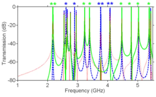
As an example, Fig. 6 presents the results for the small and intermediate periods, as in Fig. 2, but for ε=11.4. Qualitatively, the effect of the array period is here the same as that observed in Fig. 2 for the low-ε dielectric layers. Useful comparisons can also be done for Figs. 6(a) and 2(a), and for Figs. 6(b) and 2(b), in order to see the effect of variation in ε. In Fig. 6(a), one can see that the first pair of maxima of |Tyxf |=|Tbxy| looks similarly to the first pair in Figs. 2(a) and 4(a) but is located now at lower frequencies. These maxima appear at
87 .
2 GHz and 932. GHz. In particular, / 9.6 10 2 1 λ= × −
s and Δ/λ=1.92×10−2 at 872. GHz. Thus, one-way polarization conversion can appear in the structures that are 50 times thinner than the free-space wavelength. In the case when metallic parts are made of copper, losses lead to peak lowering down to −6…-5.5dB, see the inset in Fig. 6(a). In Fig. 6(b), the maxima of |Tyxf |=|Tbxy|>0.8 appear at 452. GHz, 2.48GHz, 373. GHz, 583. GHz, 4.56GHz, and
9 .
4 GHz. For the first three of them, we have |Tyxf |=|Tbxy|>0.95. In turn, the maxima of 9 . 0 | | |
|Txyf =Tbyx> are observed at 773. GHz, 3.79GHz, and 124. GHz. Hence, multiband one-way polarization conversion can be obtained in one configuration for both incident linear polarizations. Note that the distance between the first and second maxima of the twin peak near 124. GHz is just about 12MHz, see the inset in Fig. 6(b). Totally, there are ten peaks in
Fig. 6(b) that are associated with polarization conversion bands. It is noteworthy that 10 2 . 8 / 2 1 λ= × −
s and Δ/λ=1.64×10−2 at 452. GHz, while a/λ<0.37 for the entire frequency range used. The properties of the neighboring resonances can be studied in detail in the framework of the Lagrange model [2,31,32].
Fig. 7. Transmission for basic configuration with large array period at ε=11.4; solid green line - |Tyxf |=|Tbxy|, dashed blue line - |Txyf |=|Tbyx|, and dotted red line -
| T | | T | | T | | T | b yy f yy b xx f xx = = = .
The results for the large period and ε=11.4 are presented in Fig. 7. Comparing to Fig. 3(a), the considered structure differs only in the value of ε. It is seen that a much larger number of the transmission peaks appears now at a/λ<0.5, i.e., they are located more densely. Most of them are associated with the strongly pronounced asymmetric transmission.
From the obtained results, it follows that the multiband one-way polarization conversion and related high-efficiency asymmetric transmission appear in the PEC case at various parameter settings and, thus, belong to the general properties of the sandwiched structures that are based on the coupled CSRR arrays. On the other hand, this indicates that the underlying physics is mostly the same in a wide range of parameter variation. This fact can substantially simplify future design of the polarization conversion and asymmetric transmission devices. In many cases, variation in ε may give a proper solution to the problem of multiband operation. Both larger and smaller array periods have advantages and disadvantages. The former usually suggests a larger number of the bands, whereas the latter can be preferable because of weaker losses. A further decrease of the losses can be obtained owing to weaker metallization, e.g., by increasing the holes of the mesh at a fixed array period. For instance, the peak value of
15 3.
− dB is observed for the first maximum in the structure with h/p=0.9 and the same remaining parameters as in Fig. 6(a).
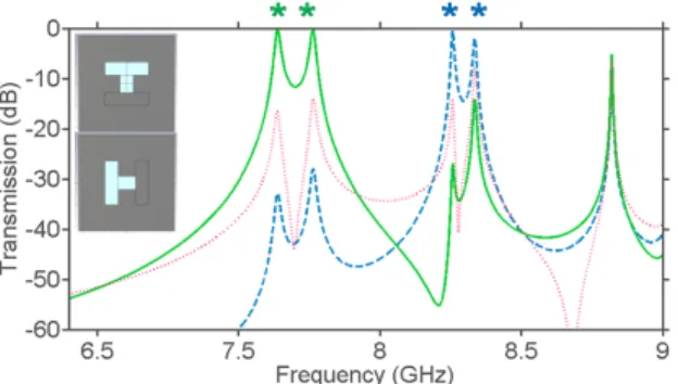
3.4 Other aperture shapes
Finally, let us briefly consider arrays of apertures that have different shape than CSRRs in Figs. 1-7. An example is presented in Fig. 8 for a structure with T-shaped apertures. It confirms, in fact, that the perfect one-way polarization conversion is not a unique property of the CSRR array based structures. The used aperture shape is obtained by shifting one of the arms of a CSRR and filling the other one with metal, compare the insets in Fig. 8 with Fig. 1. One can see that polarization conversion is achieved for both incident linear polarizations. For the twisted arrays of L-shaped or H-shaped apertures, (nearly) perfect polarization conversion has not been found. However, it can be expected that these or similar aperture shapes may also be appropriate for strong polarization conversion, provided that the parameters are properly adjusted.
Fig. 8. Transmission in case of configuration with T-shaped apertures at intermediate array period and ε=2.1; solid green line - |Tyxf |=|Tbxy|, dashed blue line - |Txyf |=|Tbyx|, and dotted red line - |T | |T | |T | |Tb |
yy f yy b xx f
xx = = = ; front-side and back-side views of unit cell are schematically shown in the upper and lower insets.
4. Conclusions
To summarize, one-way conversion of a linear incident polarization into the orthogonal one has been obtained in the structures based on aperture-type, i.e., CSRR arrays at multiple maxima of high-efficiency transmission. Thus, a properly designed metamaterial can show diodelike behavior at the maxima, i.e., it transmits the incident wave without reflections in one direction and reflects it in the opposite one. These features are found to be quite general for the sandwiched structures containing the coupled CSRR arrays and a metallic mesh, provided that the chosen geometry enables a desired combination of chirality and tunneling. This also indicates that the basic underlying physics mainly remain the same in a wide range of parameter variation. Although this study was restricted to the CSRR arrays or, strictly speaking, to the arrays of subwavelength resonance elements with U-shaped apertures, it is expected that similar transmission and polarization properties can be obtained for a much wider class of aperture shapes. In most of the considered cases, the observed perfect one-way polarization conversion leads to diodelike asymmetric transmission, when the same linear polarization state is used at the front-side and the back-side illumination. In fact, the array period and permittivity of the dielectric layers placed between the aperture arrays and the mesh are the most critical parameters for spectral location and density of the polarization conversion resonances. In the studied structures, the lowest resonance can appear when the incident wavelength is 50 times larger than the total thickness, depending on the material and geometrical parameters. Compared to the early suggested SRR array based structures with a centered metallic mesh [9], the common effect of chirality inspired one-way polarization conversion in the CSRR arrays and tunneling was utilized here for obtaining strong asymmetry in transmission within the multiple bands and suppressing the unwanted co-polarized transmission components in a wide frequency range. Thus, using twisted arrays based on subwavelength complex-shape apertures, such as CSRRs, together with evanescent-wave meshes can open a route to advanced ultrathin structures. Basic features remain the same when the losses in the metallic parts are taken into account and the possible approaches that allow decreasing the losses are indicated. From the point of view of the compromise between smaller losses and larger number of polarization conversion bands obtainable at subwavelength scale, the structures with smaller array period and higher-ε dielectric layers look promising. The possibility of combining high-efficiency transmission, perfect polarization conversion, and strong directional selectivity, which are achievable in the considered structures, can be exploited in future compact multifunctional devices. On the other hand, the performed study may serve as a general methodological example of that how the structural components and effects responsible for polarization manipulation and field
manipulation/enhancement can be combined in order to realize new functionalities and operation regimes. The basic ideas and qualitative results of this study are expected to be useful for a wide frequency range, i.e., from acoustic to terahertz frequencies.
Acknowledgments
This work is supported by the projects DPT-HAMIT, ESF-EPIGRAT, and NATO-SET-181, by TUBITAK under Project Nos., 107A004, 109A015, 109E301, and 110T306, and by Spanish Government under contract Consolider Engineering Metamaterials CSD2008-00066 and Contract No. TEC2011-28664-C02-01. Contribution of A.E.S. has partially been supported by TUBITAK in the framework of the Visiting Reseracher programme and by ESF in the framework of RNP Newfocus. M.B. acknowledges funding by the Spanish Government under the research contract program Ramón y Cajal RYC-2011-0822. E.O. acknowledges partial support from the Turkish Academy of Sciences.