ENERGY-EFFICIENT BLUETOOTH
SCATTERNET FORMATION
BASED ON
DEVICE AND LINK CHARACTERISTICS
A THESIS
SUBMITTED TO THE DEPARTMENT OF ELECTRICAL AND
ELECTRONICS ENGINEERING
AND THE INSTITUTE OF ENGINEERING AND SCIENCE
OF BILKENT UNIVERSITY
IN PARTIAL FULLFILMENT OF THE REQUIREMENTS
FOR THE DEGREE OF
MASTER OF SCIENCE
By
Canan PAMUK
August 2003
I certify that I have read this thesis and that in my opinion it is fully adequate, in scope and in quality, as a thesis for the degree of Master of Science.
Assist. Prof. Dr. Ezhan Karaşan (Supervisor)
I certify that I have read this thesis and that in my opinion it is fully adequate, in scope and in quality, as a thesis for the degree of Master of Science.
Assist. Prof. Dr. Nail Akar
I certify that I have read this thesis and that in my opinion it is fully adequate, in scope and in quality, as a thesis for the degree of Master of Science.
Prof. Dr. Hayrettin Köymen
Approved for the Institute of Engineering and Science:
Prof. Dr. Mehmet B. Baray
ABSTRACT
ENERGY-EFFICIENT BLUETOOTH
SCATTERNET FORMATION BASED ON
DEVICE AND LINK CHARACTERISTICS
Canan PAMUK
M.S. in Electrical and Electronics Engineering Supervisor: Assist. Prof. Dr. Ezhan Karaşan
August 2003
Bluetooth is a promising ad hoc networking technology. Although construction and operation of piconets are well defined in Bluetooth specifications, there is no unique standard for scatternet formation and operation.
In this thesis, we propose a distributed and energy-efficient Bluetooth
Scatternet Formation algorithm based on Device and Link characteristics
(SF-DeviL) that is compatible with Bluetooth specifications. SF-DeviL handles energy efficiency using classes of devices, battery levels and the received signal strengths. SF-DeviL forms scatternets with tree topologies that are robust to battery depletions, where devices are arranged in an hierarchical order in terms of battery power and traffic generation rate. SF-DeviL is dynamic in the sense that the topology is reconfigured when battery levels are depleted, thereby increasing the lifetime of the scatternet. Unlike many of the algorithms in the literature SF-DeviL is also multihop, i.e., there is no requirement for each node to be in the transmission range of all other nodes.
Keywords: Bluetooth, scatternet formation, energy efficiency, class of device, received signal strength, RSSI, battery level, multihop, tree topology, distributed.
ÖZET
ENERJİ-VERİMLİ
AYGIT VE BAĞ ÖZELLİKLERİNE DAYALI
BLUETOOTH MULTİPİKONET FORMASYONU
Canan PAMUK
Elektrik ve Elektronik Mühendisliği Bölümü Yüksek Lisans Tez Yöneticisi: Asist. Prof. Dr. Ezhan Karaşan
Ağustos 2003
Bluetooth, kısa mesafelerde gelecek vadeden bir tasarsız ağ teknolojisi olduğundan, son yıllarda popülerlik kazanmıştır. Bluetooth pikonetlerinin oluşum ve işleyişi Bluetooth spesifikasyonlarında belirlenmiş olmasına rağmen, multipikonet formasyon ve işleyişinin henüz bir standardı yoktur.
Çalışmamızda, aygıt ve bağ özelliklerini kullanarak multipikonet oluşumunu sağlayan bir algoritma geliştirdik. SF-DeviL (Scatternet Formation algorithm based on Device and Link characteristics) algoritması, aygıt sınıfı, pil seviyesi ve alınan sinyal gücü bilgilerini kullanarak, düğümlerin enerji verimliliğini arttırıyor. SF-DeviL, aygıtların pil güçlerine ve trafik üretim oranlarına dayalı hiyerarşik bir ağaç topolojisi oluşturarak, pil tükenmelerine karşı dayanıklı multipikonetler oluşturuyor. SF-DeviL, multipikonet iletişimi boyunca, azalan pil seviyeleriyle tekrar çalıştırılarak multipikonet ömrünü uzatan dinamik bir yapıya sahiptir. SF-DeviL ile her aygıtın diğer bütün aygıtların iletim eriminde olma zorunluluğu yoktur, kısacası multisekmedir. Anahtar Kelimeler: Bluetooth, multipikonet formasyonu, enerji verimliliği, aygıt sınıfı, alınan sinyal gücü, RSSI, pil seviyesi, multisekme, ağaç topolojisi, dağıtık.
ACKNOWLEDGEMENTS
I would like to express my gratitude to my supervisor Assist. Prof. Dr. Ezhan Karaşan for his instructive comments in the supervision of the thesis.
I would like to express my special thanks and gratitude to Assist. Prof. Nail Akar, Prof. Hayrettin Köymen for evaluating my thesis.
I would like to express my thanks to my family and Özgü for their endless love and support throughout my life.
Contents
1 Introduction ...1
2 Overview of Bluetooth Technology ...5
2.1 Topology ...5
2.2 Bluetooth Device Address ...7
2.3 Packets...9
2.3.1 Access Code ...10
2.3.2 FHS packet ...11
2.3.2.1 Class of Device/Service Field of FHS Packet ...12
2.3.2.1.1 Major Device Class...13
2.3.2.1.1 Minor Device Class...14
2.4 Bluetooth States and State Diagram ...15
2.4.1 Standby ...15
2.4.2 Inquiry ...15
2.4.3 Inquiry Scan...17
2.4.4 Page Scan...17
2.4.5 Page ...17
2.4.6 Connection...18
2.5 Connection Establishment...19
2.5.2 Page and Page Scan Procedures ...21
2.5.3 Master/Slave Role Switching ...21
2.6 Power Control ...23
3 Scatternet Formation Problem ...25
3.1 Scatternet Topology Formation ...26
3.1.1 Problems and Solutions...27
3.1.2 Published Methods for Bluetooth Scatternet Formation
...29
3.1.3 Important Aspects of SF-DeviL...32
4 SF-DeviL ...34
4.1 Motivation ...34
4.1.1 Device Grade...35
4.1.2 Received Signal Strength Grade ...37
4.2 SF-DeviL Algorithm ...38
4.2.1 Main Procedure ...39
4.2.2 Best Master Selection...42
4.2.3 Semiroot Procedure...43
4.3 Features of SF-DeviL...45
4.3.1 Energy Efficiency...46
4.3.2 Scatternet Maintenance with SF-DeviL...46
4.3.2.1 Maintaining Battery Level Changes...46
4.3.2.2 Maintaining Topology Changes ...48
4.3.3 Multihop Support ...49
4.3.4 Tree Topology...51
5 Simulations and Results...53
5.1 Assignment of Some Quantities...53
5.1.1 I/IS State Transition Parameters ...54
5.1.2 Path Loss Model...55
5.1.3 Power Control Parameters ...55
5.1.4 Assignment of Device Grades...56
5.1.5 Assignment of Received Signal Strength Grades ...57
5.2 Simulation Results ...57
5.2.1 Average Lifetime of the Scatternet ...57
5.2.1.1 Average Lifetime with Scatternet Maintenance ..59
5.2.1.1.1 Average Update Time Per Round ...62
5.2.2 Average Number of Hops ...63
5.2.3 Average Link Length ...64
5.2.4 Piconet Number ...65
5.2.5 Network Diameter...66
5.2.6 Scatternet Formation Delay ...67
5.2.7 Percentage of Discovered Neighbors...68
6 Conclusions ...69
6.1 Summary ...69
6.2 Future Work ...70
Table of Acronyms ...71
List of Figures
2.1 Topology of a piconet...7
2.2 Communication in Bluetooth provided by master polling slaves...8
2.3 Topology of a scatternet where bridge nodes have undertaken M/S, S/S and M/S/S roles ...8
2.4 Structure of BD_ADDR...9
2.5 General format of a Bluetooth packet ...9
2.6 FHS payload structure ...11
2.7 Structure of the Class of Device/Service field (first format type) ...13
2.8 State Diagram ...15
2.9 RX/TX cycle of Bluetooth transceiver in Inquiry mode...16
2.10 Bluetooth link formation ...19
2.11 Nodes alternate between inquiry (I) and inquiry scan (S) substates until they connect...21
2.12 RSSI dynamic range and accuracy ...24
4.1 Piconet (scatternet) formation based on device characteristics ...36
4.2 Scatternet formation based on link characteristics...37
4.4 Best Master Selection ...42
4.5 Relation of α and BL ...47
4.6 Illustration of ongoing device discovery by selected leaf nodes to provide node additions ...49
4.7 Illustration of an extreme example for multihop support of SF-DeviL .50 4.8 Route entry of a node in SF-DeviL scatternets ...52
5.1 I/IS procedure state transitions used in simulations ...54
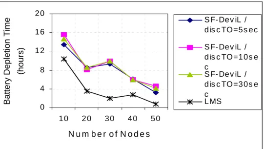
5.2 Time until the battery of first device depletes ...58
5.3 Time until the battery of first device depletes with scatternet update CASE-1 ... ...60
5.4 Number of rounds of scatternet updates for CASE-1...60
5.5 Time until the battery of first device depletes with scatternet update CASE-2 ...61
5.6 Number of rounds of scatternet updates for CASE-2...61
5.7 Average update time per round...62
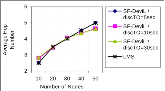
5.8 Average number of hops between source-destination pairs ...63
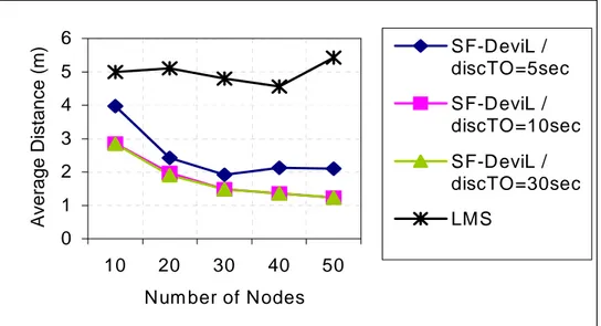
5.9 Average length of links in the scatternet ...64
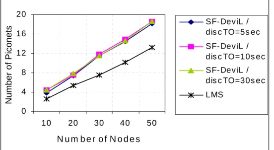
5.10 Number of piconets ...65
5.11 Network diameter ...66
5.12 Scatternet formation delay ...67
5.13 Average percentage of discovered neighbors in SF-DeviL for different timeouts ...68
List of Tables
2.1 A brief summary of control packets used for connection establishment
...10
2.2 A brief summary of access codes ...11
2.3 Description of the FHS payload...12
2.4 Major Device Classes ...14
2.5 Power classes and range of power control ...23
4.1 MAIN Procedure of SF-DeviL ...39
4.2 Semiroot Procedure of SF-DeviL...44
5.1 Intervals of the states in I/IS procedure ...54
Chapter 1
INTRODUCTION
The widespread usage of information intensive consumer devices has come up with a new networking paradigm for interconnecting them. Mobility of these devices and variety of applications have led to a wireless networking solution where the network is formed in an ad hoc manner, without the need for manual configuration and wired structure. A computer connected to a keyboard, a mouse, a pair of loudspeakers, a PDA in a personal area network or a laptop connected to a coffeemaker, a security system, a house appliance are possible situations where a wireless short-range networking solution is useful.
Bluetooth is a new and promising technology, standardized in 1999, that enables devices to form short-range wireless ad hoc networks. Its technical features such as non-line-of-sight communication, low power consumption, low cost and usage of frequency hopping physical layer are some of the features that provide advantages for Bluetooth over other competing technologies.
By today’s Bluetooth technology, Bluetooth enabled devices are capable of forming a network of maximum 8 active devices which is called a piconet. In a piconet a node has the master role and the rest have slave roles. But Bluetooth technology promises much more beyond connectivity between a small number of devices in an isolated piconet. Bluetooth can be extended to interconnect
multiple piconets to form a larger ad hoc network, which is called a scatternet, consisting of hundreds of devices. Also, multihop scatternets can provide connectivity over distances greater than the short radio range. The frequency hopping technique employed by Bluetooth enables multiple piconets to communicate at the same time and at the same place with little interference between them.
Although piconet formation and operation are well defined in Bluetooth specifications, there is no standard for scatternet formation and operation [1]. The Bluetooth specification enables the formation of a larger network from many nodes but it does not define an exact method for scatternet formation. The problem of scatternet formation can be stated to be the assignment of master, slave and bridge roles to Bluetooth nodes.
Scatternet formation is a new research problem, the studies of which gained acceleration in the last few years. Research related to Bluetooth scatternet formation can be separated into two groups: methods for scatternet formation and scatternet topology optimization.
What makes Bluetooth scatternet formation a challenge is the differences of Bluetooth networks and other networks. Bluetooth networks are highly dynamic, small (about tens of nodes), ad hoc, where devices have low computational and battery resources. Also due to frequency hopping channel, each link must be built up before communication.
The published methods for Bluetooth scatternet formation show differences in their approaches. First studies tried to form scatternets by centralized approaches and formed onehop scatternets [2][3], which later turned out to be impractical and left their place to distributed multihop scatternet formation methods.
Published methods also differ in the resulting scatternet topology: tree [4-6], star[7] and mesh topologies[8-10] are tried. In [11], an analysis of Bluetooth scatternet topologies is made, and the results show that the optimum topology is application dependent.
Bluetooth scatternet formation algorithms suitable for dynamic environments are partially addressed in [4] and [6], where group arrivals are handled by the scatternet formation method.
None of the above scatternet formation methods considers energy efficiency that is especially important in the operation and lifetime of the formed scatternet. Energy efficient techniques in routing protocols for Bluetooth scatternets have been investigated, and it is shown that a considerable gain in network life can be achieved by using distance based power control and battery level based master-slave switch [12]. But such techniques are not considered for formation or operation of scatternets.
In this thesis, we propose a new scatternet formation algorithm named as DeviL (Scatternet Formation based on Device and Link Characteristics). SF-DeviL runs in a distributed fashion and forms energy efficient, multihop scatternets. SF-DeviL is appropriate to handle dynamic environments.
The primary goal of SF-DeviL is to form a scatternet where energy management can be done efficiently throughout the formation and lifetime of the network. SF-DeviL handles energy efficiency by using: 1) classes of devices, 2) the received signal strengths and 3) battery levels of devices. SF-DeviL uses class of device information, e.g., it assigns roles to nodes by looking whether it is a laptop, a PDA, a sensor etc. None of the published scatternet formation methods consider the class of device information, which can expose many features of a node such as mobility, traffic generation rate and battery capacity. By SF-DeviL, each node measures received signal strength for each link and quantizes it to give priority to shorter links. Using power control at these shorter links results in less power requirement for the transmission of a packet and reduces interference to other systems using the same frequency band. SF-DeviL also keeps track of battery levels throughout scatternet communication and rearranges the scatternet where it pushes low battery level devices toward the leaf nodes of the tree, in order to increase lifetime of each
device and the lifetime of the scatternet. As a result, SF-DeviL forms scatternets that are robust to mobility and battery depletions.
Chapter 2 is a brief overview of Bluetooth technology to constitute a background. Chapter 3 is a discussion on open problems regarding scatternets, challenges and solutions to the scatternet formation problem, an overview of published scatternet formation solutions. In Chapter 4, SF-DeviL is explained in detail and its features are discussed. Chapter 5 includes performance evaluation of SF-DeviL that is done through simulations and simulation results are clarified. The thesis concludes with Chapter 6 where a summary of the study and future work is given.
Chapter 2
OVERVIEW OF BLUETOOTH
TECHNOLOGY
The Bluetooth wireless technology operates in the unlicensed 2.4-2.5 GHz Industrial, Scientific, Medicine (ISM) frequency band. Bluetooth radio employs a fast (1600slots/sec) frequency hopping spread spectrum (FHSS) technique that gives robustness against interference and fading. The radio hops in a pseudo-random fashion on 79 one-MHz channels. A slotted channel is applied with a nominal slot length of 625 µs. For full duplex transmission, a Time-Division Duplex (TDD) scheme is used. On the channel, information is exchanged through packets. Each packet is transmitted on a different hop frequency. A packet nominally covers a single slot, but can be extended to cover up to three or five slots.
The modulation technique is binary Gaussian frequency shift keying (GFSK), and the band rate is 1Msymbol/sec. The bit time is 1msec, and the raw transmission speed is 1Mb/sec.
Bluetooth supports both voice and data communication using 2 types of physical links: Asynchronous Connectionless (ACL) and Synchronous Connection-Oriented (SCO). SCO is a symmetric, point-to-point link between a
master and a specific slave. The master will send SCO packets at regular intervals. Thus, an SCO link can be considered to be a circuit-switched connection. SCO links support time-delay sensitive traffic such as voice. An ACL link provides a packet-switched communications between a master and a slave. Briefly, Bluetooth uses a combination of circuit and packet switching. Each voice channel supports a 64 kb/s synchronous (voice) channel in each direction. The asynchronous channel can support maximal 723.2 kb/s asymmetric (and still up to 57.6 kb/s in the return direction), or 433.9 kb/s symmetric.
Bluetooth has low power consumption. Bluetooth specification allows for three different types of radio transmit powers:
• Class 1 = 100mW (20dBm) • Class 2 = 2.5mW (4dBm) • Class 3 = 1mW (0dBm)
These power classes allow Bluetooth devices to connect at different ranges. The maximum range for a Class 1 is 100m, whereas it is 10m for Class 3. Since Bluetooth applications are mostly short-range today, owing to the importance of low energy consumption for mobile devices, Class 2 and 3 are used mostly.
One of the features of Bluetooth that accelerates its penetration into the market is its low cost which is aimed to be taken down to $5 (currently $10).
2.1 Topology
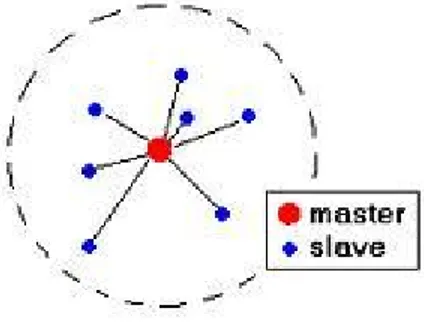
The smallest operation unit of Bluetooth is a piconet. A piconet consists of a master and up to seven active slave nodes as shown in Figure 2.1. Any device can become a master or a slave. These roles are only logical states.
The master regulates and controls the traffic by polling the slaves in a Deficit Round Robin fashion. A slave is only allowed to transmit upon receiving from the master as shown in Figure 2.2. During a time slot one Bluetooth device may transmit. The master starts its transmission in even-numbered time slots only, and the slave starts its transmission in odd-numbered time slots only.
Figure 2.1: Topology of a piconet
Slaves of a piconet are synchronized to the master’s frequency hop sequence, which is particular to each piconet. Slaves calculate this particular hop sequence using the master’s Bluetooth device address (BD_ADDR) and clock information that are exchanged during master-slave connection establishment procedure. To identify each slave, the master assigns a locally unique active member address (AM_ADDR) to the slaves participating in active communications in the piconet.
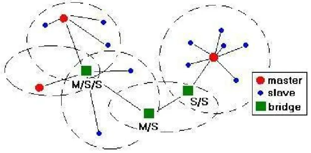
Figure 2.2: Communication in Bluetooth provided by master polling slaves Piconets can co-exist in time and space since each piconet uses a different frequency hop sequence. The network formed by connecting several piconets via shared nodes is called a scatternet, and the shared nodes are called bridges. Bridge nodes may be master in one piconet and slave in the other (M/S), or slave in several piconets (S/S, S/S/S...etc.) or master in one piconet and slave in the others (M/S/S) as illustrated in Figure 2.3. Bridge node cannot be master in more than one piconet since the master’s frequency hop sequence should be particular to a single piconet. Bridge nodes participate in different piconets on a time-division multiplex basis.
Figure 2.3: Topology of a scatternet where bridge nodes have undertaken M/S, S/S and M/S/S roles
2.2 Bluetooth Device Address
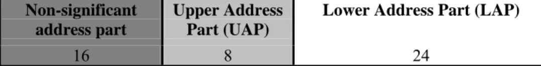
Bluetooth device address (BD_ADDR) uniquely identifies each Bluetooth device and it is 48 bits long. The format of the BD_ADDR is as shown in Figure 2.4.
Non-significant address part
Upper Address Part (UAP)
Lower Address Part (LAP)
16 8 24
LSB MSB
Figure 2.4: Structure of BD_ADDR
BD_ADDR is used for calculating various access codes, described in detail below. Frequency hopping sequences are calculated from these access codes. Thus, to know a hopping sequence of a device one needs to know the device’s BD_ADDR.
2.3 Packets
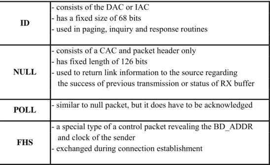
The packets used on the piconet are related to the physical links they are used in. For each of the SCO link and the ACL link, 12 different packet types can be defined. Four common packet types that are used during connection establishment procedure are ID, NULL, POLL and FHS packets, which are listed in Table 2.1. A general format of a Bluetooth packet is shown in Figure 2.5.
Access Code Header Payload
72 54 0-2745
LSB MSB
- consists of the DAC or IAC - has a fixed size of 68 bits
- used in paging, inquiry and response routines ID
- consists of a CAC and packet header only - has fixed length of 126 bits
- used to return link information to the source regarding the success of previous transmission or status of RX buffer NULL
- similar to null packet, but it does have to be acknowledged POLL
- a special type of a control packet revealing the BD_ADDR and clock of the sender
- exchanged during connection establishment FHS
Table 2.1: A brief summary of control packets used for connection establishment
2.3.1 Access Code
Access code is derived from lower address part (LAP) of BD_ADDR. Access code is a field of a Bluetooth packet. There are 3 types of access codes: Channel Access Code (CAC), Device Access Code (DAC), and Inquiry Access Code (IAC). IAC can be general (GIAC) or dedicated (DIAC).
A Bluetooth unit that tries to discover devices in range sends packets with GIAC since no prior knowledge of BD_ADDR of the neighboring device exists. After getting the BD_ADDR of the neighboring device, it sends packets with DAC to be received by that specific device.
Inside a piconet, packets with a specific CAC to that piconet are exchanged so that any other packet belonging to another piconet, i.e. with a different CAC is not accepted.
- The channel access code identifies a piconet. This code is included in all packets exchanged on the piconet channel.
Channel Access Code (CAC):
- Derived from master’s BD_ADDR.
- This code is included in a packet sent to a specific device. It is used used during page and page scan substates of the connection establishment procedure. Device Access Code
(DAC):
- Derived from paged unit’s BD_ADDR.
- This code is included in a packet sent to any device for discovery purposes. It is used during inquiry and inquiry scan substates.
Inquiry Access Code
(IAC): - There is one general IAC (GIAC) and 63 dedicated IACs (DIAC) used to inquire for specific classes of devices.
Table 2.2: A brief summary of access codes
2.3.2 FHS Packet
The FHS packet is a special control packet revealing, among other things, the Bluetooth device address and the clock of the sender. The payload contains 144 information bits plus a 16-bit CRC code. The payload is coded with a rate 2/3 FEC bringing the gross payload length to 240 bits. The FHS packet covers a single time slot.
The structure of the payload of the FHS packet is as shown in Figure 2.6, where brief explanations of fields are listed in Table 2.3.
Parity bits
LAP Un-defined
SR SP UAP NAP Class of Device AM_ ADDR CLK Page scan mode 34 24 2 2 2 8 16 24 3 26 3 LSB MSB
NAP-UAP-LAP BD_ADDR of the unit that sends the FHS.
Parity bits Form the first part of the sync word of the access code of the unit that sends the FHS.
SR Scan Repetition field, indicates the interval between two consecutive page scan windows.
SP Scan period, indicates the period in which the mandatory page scan mode is applied after transmission of an inquiry response message.
CLK Contains the value of the native system clock of the unit that sends the FHS packet, sampled at the beginning of the transmission of the access code of this FHS. This clock value has a resolution of 1.25ms.
Page Scan Mode Indicates which scan mode is used by default by the sender of the FHS.
Table 2.3: Description of the FHS payload
The FHS packet plays an important role in Bluetooth connection establishment. For communication to take place between two Bluetooth devices, their frequency hop sequences have to be the same. As mentioned previously, frequency hop sequence of a piconet is calculated using the master’s access code and clock information. Thus, a slave candidate has to get this information which is exchanged inside frequency hop synchronization (FHS) packet. Briefly, for two devices to connect, the device that will undertake slave role has to get FHS packet from the master.
2.3.2.1 Class of Device/Service Field of FHS Packet [13]
The class of the device where the Bluetooth module is embedded is known by the Bluetooth module. Furthermore, this knowledge is exchanged between two devices establishing a link. The device class information together with service
information is exchanged by the 24 bit long Class of Device/Service (CoD) field of the FHS packet as shown in Figure 2.6.
The Class of Device/Service (CoD) field has a variable format. The format is indicated using the 'Format Type field' within the CoD. In the “format #1” of the CoD, i.e. “Format Type field = 00”, 11 bits are assigned for device classes and 11 for service classes as shown in Figure 2.7.
Format type Major Device Address Minor Device Address Service Classes 2 6 5 11 LSB MSB
Figure 2.7: Structure of the Class of Device/Service field (first format type) Service classes are primarily of a “public service” nature. Currently 9 service classes are defined: Limited discoverable mode, positioning, networking (LAN, Ad hoc, ...), rendering (printing, speaker,...), capturing (scanner, microphone,...), object transfer, audio, telephony, information (WEB-server, WAP-server,...). 2 bits of Service Classes Field are reserved for future use.
The remaining 11 bits of CoD field are divided into two subcategories: major and minor device classes and are used to indicate device type category and other device-specific characteristics.
2.3.2.1.1 Major Device Class
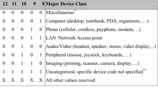
The Major Class segment is the highest level of granularity for defining a Bluetooth Device. The main function of a device is used to determine the major class grouping. There are 32 different possible major classes. The assignment of this Major Class field is given in Table 2.4.
12 11 10 9 8 Major Device Class
0 0 0 0 0 Miscellaneous*
0 0 0 0 1 Computer (desktop, notebook, PDA, organizers, ... ) 0 0 0 1 0 Phone (cellular, cordless, payphone, modem, ...) 0 0 0 1 1 LAN /Network Access point
0 0 1 0 0 Audio/Video (headset, speaker, stereo, video display,...) 0 0 1 0 1 Peripheral (mouse, joystick, keyboards, ... )
0 0 1 1 0 Imaging (printing, scanner, camera, display, ...) 1 1 1 1 1 Uncategorized, specific device code not specified** X X X X X All other values reserved
Table 2.4: Major Device Classes
2.3.2.1.2 Minor Device Class
The 'Minor Device Class field' (bits 2 to 7 in the CoD), are to be interpreted only in the context of the Major Device Class (but independent of the Service Class field). Thus the meaning of the bits may change, depending on the value of the 'Major Device Class field'. For example, by setting the major class field as ‘computer’, different settings of the minor device class field end up with desktop, server-class computer, laptop, handheld PC/PDA or wearable computer device classes.
Many of the minor device class field bits are reserved for future use, the number of which depends on the major device class. 3 bits for computer, phone and LAN/Network access point major classes; 2 bits for imaging major class and 1 bit for audio/video major class are reserved.
* Used where a more specific Major Device Class code is not suited.
2.4 Bluetooth States and State Diagram
At any time, a Bluetooth device is in one of a number of different states. There are two major states: standby and connection; in addition, there are substates, inquiry, inquiry scan, page, page scan, inquiry response, master response and slave response which are interim states that are used to add new slaves to a piconet. A simplified state diagram is given in Figure 2.8.
Figure 2.8: Bluetooth Device State Diagram
2.4.1 Standby
Standby state is the default state of the Bluetooth device. In it the device uses a low power mode.
2.4.2 Inquiry (I)
A unit that wishes to discover other Bluetooth units in range enters inquiry substate. It continuously transmits inquiry messages at different hop frequencies. Between inquiry transmissions the unit listens for responses (which is an FHS packet). It transmits two inquiry messages in each TX slot and listens for a response in the preceding RX slot as shown in Figure 2.9.
If the response is received, it is not acknowledged and the probing unit continues with the inquiry transmissions. The unit leaves inquiry state either when it received a predetermined number of responses or when the InquiryTO timer runs out.
Figure 2.9: RX/TX cycle of Bluetooth transceiver in Inquiry mode
The inquiry message broadcast by the source does not contain any information about the source. However, it may indicate which class of devices should respond. There is one general inquiry access code (GIAC) to inquire for any Bluetooth device, and a number of dedicated inquiry access codes (DIAC) that only inquire for a certain type of devices.
During an inquiry substate, the discovering unit collects the Bluetooth device addresses and clocks of all units that respond to the inquiry message. It can then, if desired, make a connection to any one of them by means of the previously described page procedure.
A hopping sequence consists of two groups of frequencies: train A and train B (each of which are 16 frequencies long). According to the Bluetooth standard [1] a single train must be repeated Ninquiry =256 times before another train is used. At least three train switches are needed (4 train sequences). Since each train is 10ms long, the inquiry procedure can take up to 10.24s.
It is not specified how often a unit should leave standby or connection to perform inquiry. It might be periodic or upon user request. These choices are left up to the implementers.
2.4.3 Inquiry Scan (IS)
A unit that wishes to be discovered by other Bluetooth in range enters inquiry scan substate. It continuously listens for inquiry messages at different hop frequencies.
The period of inquiry scan can be 0s (continuous scan) – R0, 1.28s – R1 mode, or 2.56s – R2 mode. A scanning unit listens for an IAC for Tw_inquiry_scan seconds. Tw_inquiry_scan should be long enough to scan 16 frequencies (1 train). Because one train lasts for 10ms, Tw_inquiry_scan should also be 10ms. During these 10ms the receiver of the scanning device listens on a single frequency determined by the inquiry scan hopping sequence and the current value of the device’s clock. The scanning device changes its listening frequency according to inquiry hopping sequence every 1.28s.
2.4.4 Page Scan (PS)
Page scan works similar to inquiry scan, however, in page scan a unit listens for its own unique DAC and it alone can respond. There are 32 paging frequencies, which comprise a page hopping sequence, determined by the paged unit’s BD_ADDR. Every 1.28s, a different listening frequency is selected as in inquiry scan. During a scan window the unit listens on one frequency.
2.4.5 Page (P)
When a Bluetooth unit wants to make a connection to another unit, it pages that unit. Paging means sending an ID packet with a certain DAC in it over and over again until a response is received. The master does not know exactly when the
slave wakes up and on which hop frequency, therefore it transmits a train of identical DACs at different hop frequencies and listens in between for responses. The master uses the slave’s BD_ADDR and an estimate of the slave’s clock to determine the page hopping sequence. To compensate for the uncertainty in the knowledge of a slave’s clock, the master will send its page message during a short time interval on a number of wake-up frequencies. During each transmission slot the master sequentially transmits on 2 different hopping frequencies. The page hopping sequence of 32 frequencies is divided into two trains of 16 frequencies each and each train is repeated for Npage times or until a response is received. Paging ends until a response is received or timeout value PageTO is exceeded.
2.4.6 Connection
In the connection state, the connection has been established and packets can be sent back and forth. In both units, the channel (master) access code and the master Bluetooth clock are used. The master starts its transmission in even slots, the slave starts its transmission in odd slots.
The connection state starts with a POLL packet sent by the master to verify the switch to the master’s timing and channel frequency hopping. The slave can respond with any type of packet. If the slave does not receive the POLL packet or the master does not receive the response packet for newconnectionTO number of slots, both devices will return to P/PS substates.
The Bluetooth units can be in several modes of operation during the connection state: active mode, sniff mode, hold mode, and park mode.
2.5 Connection Establishment
Link formation or connection establishment in Bluetooth is a complicated and a long lasting (2,5msec - 681,875msec) procedure that has two phases. The first phase called inquiry is unique to Bluetooth and is instrumental in making a connection possible. This procedure is necessary because Bluetooth units do not know anything about each other prior to connection establishment, including each other’s addresses and frequency hop sequences. This fact makes connection establishment a challenge. The second procedure is called paging, which has its analogs in other technologies. Figure 2.10 shows how a link is established in Bluetooth.
2.5.1 Inquiry and Inquiry Scan Procedures
A Bluetooth unit either enters inquiry state to discover other devices or inquiry scan state to be discovered by other devices in range. Every Bluetooth unit knows the GIAC, thus every unit can calculate the inquiry hopping sequence to perform inquiry. Thus, the inquirer, sends ID packets with GIAC as explained in detail in section 2.4.2.
The inquiry scanning unit, upon receiving an inquiry message, enters inquiry response substate and should respond with a FHS packet which contains the recipient’s address and clock information. But, because several units might respond to an inquiry at the same time, a protocol for slave inquiry response in order to avoid or minimize the probability of collisions is needed. Thus, when the inquiry scanning unit receives an inquiry message it generates a random number, RAND, uniformly selected between 0 and 1023, returns to Connection or Standby state for duration of RAND slots. After this random backoff time, it returns to the inquiry response substate and on the first inquiry message received it will answer with an FHS packet. After sending the FHS packet, the inquiry scanning unit enters PS substate and waits to be paged for a certain time.
The inquirer unit knows the BD_ADDR and clock of the inquiry scanning unit after getting the FHS packet and can derive the frequency hopping sequence and DAC of the inquiry scanning unit. Thus, the inquirer can now page the inquiry scanning and enters page substate.
For two devices to be able to start link establishment procedure, one has to be in the inquiry and the other in the inquiry scan state. Since these substates are not assigned centrally, devices have to alternate between sender and receiver modes until they connect. In [2], it is shown that the alternation should be random. Connection is established when opposite modes coincide for long enough as illustrated in Figure 2.11.
Figure 2.11: Nodes alternate between inquiry (I) and inquiry scan (S) substates until they connect
2.5.2 Page and Page Scan Procedures
The sender, having entered page substate upon receiving the FHS packet, pages the page scanning unit at the frequency that it is listening to. The page scanning unit answers with an ID packet containing DAC. The pager responds by sending the FHS packet. The page scanning unit uses the FHS information to determine the channel hopping sequence and the phase of the pager and becomes the slave of the point to point connection. It then acknowledges the FHS packet with another DAC packet. As soon as the acknowledgment is received, “the paging unit becomes the master of the connection” and may start exchanging data with the synchronized slave.
2.5.3 Master/Slave Role Switching
Bluetooth supports role switching between master and slave nodes, which means that slave becomes the master and master becomes the slave.
There are several occasions when a master-slave (MS) switch is desirable. Firstly, a MS switch is necessary when a unit paging the master of an existing piconet wants to join this piconet, since, by definition, the paging unit initially is master of a "small" piconet only involving the pager (master) and the paged (slave) unit.
Secondly, MS switch is done when a slave in an existing piconet wants to set up a new piconet, involving itself as master and the current piconet master as slave. The latter case implies a double role of the original piconet master; it becomes a slave in the new piconet while still maintaining the original piconet as master.
Thirdly, a much more complicated example is when a slave wants to fully take over an existing piconet, i.e., the switch also involves transfer of other slaves of the existing piconet to the new piconet. Clearly, this can be achieved by letting the new master setup a completely new piconet through the conventional paging scheme. However, that would require individual paging of the old slaves, and, thus, take unnecessarily long time. Instead, letting the new master utilize timing knowledge of the old master is more efficient. As a consequence of the MS switch, the slaves in the piconet have to be transferred to the new piconet, changing their timing and their hopping scheme.
By MS switch, exchange of FHS packets is done. BD_ADDRs, clock information and AM_ADDRs are exchanged through these FHS packets. The new slave gets the AM_ADDR of the older slave. Moreover, since the piconet parameters are derived from the device address and clock of the master, an MS switch inherently involves a redefinition of the piconet as well: a piconet switch. The new piconet's parameters are derived from the former slave's device address and clock. Finally, for the master and slave involved in the role switch, the MS switch results in a reversal of their TX and RX timing: a TDD switch. A detailed description of how an MS switch is done is present in [1].
2.6 Power Control
A Bluetooth transceiver has a Receiver Signal Strength Indicator (RSSI). RSSI makes power control possible. It measures the strength of the received signal and determines if the transmitter on the other side of the link should increase or
decrease its output power level. The transmitter, on the other side decreases/increases the power with steps, where the step size can be selected between the maximum of 8 dB and the minimum of 2 dB.
Power control is required for power class 1 devices whereas it is optional for class 2 and 3. The power control is used for limiting the transmitted power over 0 dBm. Power control capability under 0 dBm is optional and could be used for optimizing the power consumption and overall interference level. A class 1 equipment with a maximum transmit power of +20 dBm must be able to control its transmit power down to 4 dBm or less, whereas a class 2 or 3 equipment is able to decrease its transmit power to a lower power limit of -30dBm or less as seen in Table 2.5.
The RSSI measurement compares the received signal power with two threshold levels as shown in Figure 2.12. The lower threshold level corresponds to a received power between -56 dBm and 6 dB above the actual sensitivity of the receiver. The actual sensitivity level of Bluetooth receivers should be – 70dBm or better. Thus the lower threshold should be between –56dBm and about –64dBm. The upper threshold level is 20 dB above the lower threshold level to an accuracy of +/- 6 dB.
Power
Class Maximum Output Power (Pmax) Minimum Output Power (Pmin)* Power Control
1 100mW (20dBm) 1mW (0dBm) Pmin<+4 dBm to Pmax Optional: Pmin** to Pmax 2 2,5mW (4dBm) 0,25mW (-6dBm) Optional: Pmin** to Pmax
3 1mW (0dBm) N/A Optional: Pmin** to Pmax
Table 2.5: Power classes and range of power control
* Minimum output power at maximum power setting.
** The lower power limit Pmin < -30dBm is suggested but is not mandatory, and may be chosen
UPPER THRESHOLD
20dBm ± 6dBm
max= -56dBm LOWER
min= -64dBm THRESHOLD
Chapter 3
SCATTERNET FORMATION
PROBLEM
Bluetooth technology was originally optimized for establishing point-to-point connection between devices. Today Bluetooth is seen as a promising technology for ad hoc networking and promises much more beyond connectivity between a small number of devices in an isolated piconet. Bluetooth can be extended to interconnect multiple piconets to form a scatternet, consisting of large number of devices. Also, multihop scatternets, where each device is not required to be in communication range of all other devices, can provide connectivity over distances greater than the short radio range. The frequency hopping technique employed by Bluetooth enables multiple piconets to communicate at the same time and at the same place with little interference between them.
The networking point of view for Bluetooth requires to solve new problems. These problems can be stated as:
I. Scatternet formation II. Scheduling of bridge nodes III. Routing in Bluetooth scatternets
In this thesis, the scatternet formation problem is investigated. This chapter includes an investigation of the problem and literature survey of the scatternet formation algorithms.
3.1 Scatternet Topology Formation
The Bluetooth specification enables the formation of a larger network from many nodes but it does not define an exact method for scatternet formation. The problem of scatternet formation can be stated to be the assignment of master, slave and bridge roles to Bluetooth nodes. Before considering the primary problems and solutions about scatternet formation, an evaluation of differences between Bluetooth networks and other networks should be done.
The differences between Bluetooth networks and other networks are emphasized as follows [14]:
I. Spontaneous network: This means the Bluetooth networks are ad hoc networks where they forward the packets of each other and they do not need an infrastructure to form a network. Also the nodes must maintain the membership information.
II. Isolation: The Bluetooth nodes cannot rely on infrastructure based services such as Domain Name Service (DNS) [15]. They must operate with distributed methods.
III. Simple devices: The devices are intended to be cheap. They have low computational and battery resources. This means that every approach must take the power save as a strong requirement into account.
IV. Small multihop* networks: The Bluetooth networks should be small networks. There should not be more members than about some hundred nodes. The packet forwarding is done by the nodes themselves.
V. Connection-oriented technology: Each link used for communication must be built up before. The cost of the active link is relatively high from the power resources point of view. A solution should make an effort on reducing the number of active links needed.
3.1.1 Problems and Solutions
Due to the above differences, primary problems with scatternet formation and solutions can be summarized as follows:
I. Mobility: The spontaneous network property of Bluetooth mentioned in [14] emerges from the mobile nature of devices. Since devices are mobile, topology changes may take place frequently in a scatternet, such as node additions and deletions (failure: break out, battery depletion etc.).
SOLUTION: The scatternet formation algorithm should be dynamic. It should handle any topology changes during formation and throughout the operation of the scatternet.
II. Isolation: Initially, devices have no knowledge about their surroundings. SOLUTION: A centralized scatternet formation needs extensive messaging and is practically inefficient. The failure of the center or any dynamic changes requires restart of the formation process. So, a distributed approach should be used.
III. Power efficiency: Since Bluetooth modules are used mostly by simple mobile devices, powers of these devices are supplied by batteries.
SOLUTION: So energy must be used efficiently. The scatternet formation procedure should use as few message exchanges as possible. Also role assignment should be done such that power is used as efficient as possible to increase the lifetime of the scatternet.
VI. Small multihop networks: Assuming that each Bluetooth unit is in the transmission range of the others requires the devices to be confined into an area smaller than 10√2 x 10√2 (class 3), which is a reasonable assumption for small conference meeting applications or personal area networks. But Bluetooth is considered as a promising technology for sensor networks where hundreds of sensors are spread over a larger area (due to improved security provided by frequency hopping). Also usage of Bluetooth technology in smart home applications may also require multihop scatternets.
SOLUTION: The scatternet formation algorithm should form multihop scatternets. A device being heard by a single scatternet member must be enough for it to be connected to the scatternet.
VII. Topology: Since each link must be built up before communication and the assignment of links is a critical issue in scatternet formation, topology of the formed scatternet is important. An active link means cost, on the other hand, establishing links only to part of neighbors may lead to longer paths (increasing cost) or even a situation where some of neighbors are unreachable.
SOLUTION: One extreme way is to establish links to all the neighbors so that every neighbor is reachable in one hop. The other extreme is to
establish the minimal number of links yet guarantee the reachability where tree topologies are formed. There are also proposed interim solutions that create mesh topologies. The optimum solution to this problem is shown to be application dependent [11].
IV. Delay: One of the problems with scatternet formation is being time-critical. Scatternet formation operation should be completed as fast as possible looking from a user perspective.
SOLUTION: Delay of scatternet formation highly depends on the protocol. But proposed solutions show that it depends highly on the distributedness of the protocol and the method device discovery (inquiry/inquiry scan) is done. The more distributed and the less time required for device discovery, the faster the scatternet is formed.
3.1.2 Published Methods for Bluetooth Scatternet Formation
Studies related to Bluetooth scatternet formation can be separated into two groups. One group of studies concentrates on methods for scatternet formation while the other group concentrates on scatternet topology optimization.
The published methods for Bluetooth scatternet formation show differences in their approaches to some of the above problems:
I. Isolation: First studies tried to form scatternets by centralized approaches [2][3], which later turned out to be impractical and left their place to distributed scatternet formation studies.
II. Multihop: First published studies formed onehop scatternets [2-4][16]. Latter studies concentrated on multihop scatternets, owing to the emergence of applications that need connectivity over distances greater than the short radio range.
III. Topology: Until 2003, all of the formed scatternet had tree topologies [4-6]. New studies have started to investigate also star, ring and mesh topologies [7-10]. In [11], an analysis of Bluetooth scatternet topologies is made and the results showed that the optimum topology is application dependent.
IV. Mobility: Dynamicity of Bluetooth scatternet formation algorithm has not yet been addressed fully. [4] and [6] have investigated the time requested to reconfigure the scatternet after arrival of a group of nodes. V. Power-efficiency: This problem has not been investigated yet for
Bluetooth networks. Our study is the first in considering power efficient methods for scatternet formation.
VI. Delay: Scatternet formation delay has always been a parameter taken care in nearly all of the studies.
Instead of a distributed approach, a centralized approach is used in [2] and [3]. The formation algorithm in [3] first partitions the network into independent piconets, and then elects a ‘super-master’ that knows about all the nodes. However, the resulting network is not a scatternet, because the piconets are not inter-connected.
A similar algorithm is the Bluetooth Topology Construction Protocol (BTCP) [2]. BTCP has three phases: (I) a coordinator is elected with a complete knowledge of all devices, (II) this coordinator determines and tells other masters how a scatternet should be formed, and (III) the scatternet is formed according to the instructions. This method addresses the problem of scatternet formation however it has some disadvantages. Firstly, it is a centralized approach and shares the drawbacks described in the previous section. If the coordinator fails, the formation protocol has to be restarted. BTCP is not suitable for dynamic environments where devices can join and leave after the scatternet is formed since there is no efficient method how to recalculate the network topology.
BTCP’s timeout value for the first phase would affect the probability that a scatternet is formed.
LMS is a distributed formation algorithm that is similar to BTCP [16]. LMS uses one phase and overcomes the timeout problem. Since the protocol’s timeout value for each round affects the overall performance of the protocol—the scatternet is formed with certainty. This algorithm also has the drawback of forming onehop networks.
The shortcoming of all the above protocols is that it assumes a onehop network, where every node should be in the radio range of all others. The rest of the protocols produce multihop scatternets.
Among these, the protocols resulting in tree topologies are: Tree Scatternet Formation (TSF) protocol [4], Bluetree [5] and Shaper [6]. TSF and Shaper dynamically reconfigure the scatternet after topological variations, but TSF is a onehop scheme.
Bluetree [5] is a practical protocol for forming connected scatternets, which has two variations, namely, Blueroot Grown Bluetree and Distributed Bluetree. The former builds a scatternet starting from some specified node called Blueroot, while the latter speeds up the scatternet formation process by selecting more than one root for tree formation and then merging the trees generated by each root. One distinct feature of the Bluetree scheme is that all resulting scatternets assume a topology of spanning tree, where the parent node is master and the children nodes are slaves. Though the scheme selects the smallest possible number of links to form a connected scatternet and tries to spend the least of network resources on maintaining the scatternet, the resulting scatternet has inherent deficiency due to its hierarchical structure. First, it lacks reliability. If one parent node is lost, all the children and grandchildren nodes below it will be separated from the rest of the network and part of the tree or even the whole tree has to be rebuilt in order to retain the connectivity. In a mobile network, this may happen quite frequently, making the Bluetree very susceptible.
Another class of multihop proposals define algorithms that produce connected scatternet by exploiting clustering schemes for ad hoc networks. BlueStars [7], BlueMesh [8] protocols and [9] generate mesh scatternets with multiple paths between any pair of nodes. BlueMesh and [9] allows each master to select at most 7 slaves. [9] assumes that each node knows its position and that of its neighbors which is impractical for Bluetooth applications.
The group of studies that concentrate on scatternet topology optimization are [11] and [17-20]. This issue is faced in [18] and [20] by adopting centralized approaches. In [18], the aim is minimizing the load of the most congested node in the network, while [20] discusses the impact of different metrics on the scatternet topology. A distributed approach based on simple heuristics is presented in [19]. The results of [17] reveal some important performance implications of scatternet design decisions serving guidelines for scatternet formation algorithms.
3.1.3 Important Aspects of SF-DeviL
None of the above scatternet formation methods considers energy efficiency which is especially important in the operation and lifetime of the formed scatternet. Energy efficient techniques in routing protocols for Bluetooth scatternets have been investigated, and it is shown that a considerable gain in network life can be achieved by using distance based power control and battery level based master-slave switch [12]. But such techniques are not considered for formation or operation of scatternets.
Energy efficiency becomes very important for tree scatternet topologies, where the root node and nodes closer to the root need to handle significant transit traffic and thus may run out of battery.
SF-DeviL algorithm takes care of energy efficiency at scatternet formation procedure and throughout the operation of the scatternet. The most important aspects of SF-DeviL can be summarized as following, where the first three
properties of SF-DeviL serve for energy efficiency, while the last serves for connectedness.
SF-DeviL,
9 Uses ‘class of device’ information, i.e. assigns roles to nodes by looking whether it is a laptop, a PDA, a sensor etc.
9 Measures received signal strength and quantizes it; and establishes links giving priority to shorter links.
9 Keeps track of battery levels throughout scatternet communication and re-arranges the scatternet so that ‘busy’ nodes have more energy.
9 Unlike other scatternets formation methods, slaves choose their masters. By this way, the possibility of unconnectedness is eliminated.
Briefly, by considering the device and link characteristics and keeping track of battery levels, SF-DeviL increases the robustness of the scatternet in dealing with topology changes and battery depletions.
Chapter 4
SF-DeviL
SF-DeviL (Bluetooth Scatternet Formation algorithm based on Device and Link characteristics) is an energy-efficient, distributed and dynamic algorithm for the formation of Bluetooth multihop, tree structured scatternets. SF-DeviL is not only a scatternet formation algorithm, but also a scatternet maintenance algorithm that runs throughout the lifetime of the scatternet. Description and a detailed investigation of the features of SF-DeviL are given in this chapter.
4.1 Motivation
The main objective of SF-DeviL is energy-efficiency. Bluetooth units are mostly used by mobile devices, and energy is supplied by batteries that have limited lifetime. Battery depletion results in failure of the node, which is an unwanted situation looking from a user perspective, and also it may require reorganization of the whole scatternet.
Besides this main objective, SF-DeviL is aimed to run in a distributed manner, to adapt to changes of topology, to handle multihop operation and to ease routing by choosing appropriate topology.
SF-DeviL uses two parameters, which are particular to the algorithm, to achieve these goals: Device Grade and Received Signal Strength Grade.
4.1.1 Device Grade
SF-DeviL uses the class of the device that the Bluetooth module is embedded onto in the scatternet formation, i.e., scatternet is formed by taking into consideration whether the device is a laptop, a desktop or a PDA etc.
Device class is known to Bluetooth module and is exchanged with neighboring devices during connection establishment procedure by the class of
device/service field of the frequency hop synchronization packet explained in Section 2.3.2. Battery capacity and traffic generation rate of a node
can be predicted using class of the device information.
Since master and bridge nodes are loaded more compared to slaves, a device with a high battery capacity and high traffic generation rate is better to be chosen as master or bridge. If a device, having a high battery capacity and is likely to generate high traffic, is chosen to be a master or a bridge, the resulting scatternet will be more stable and energy-efficient. For example, for the scenario illustrated in Figure 4.1, choice of a mobile phone as the master of several laptops is not an intelligent decision for a robust network for several reasons: 1. A mobile phone has lower battery capacity than a laptop so it might run out
of battery requiring reorganization of the scatternet.
2. A mobile phone is possibly more mobile than a laptop. Position change of a master requires a more difficult rearrangement of topology than the movement of a slave.
3. Since a laptop generates high rate traffic, the mobile phone has to spend its resources to forward packets from one laptop to the other. Having a high traffic generation rate device as a master is a better choice.
Figure 4.1: Piconet (scatternet) formation based on device characteristics
Not only the battery capacity, but also the battery level of a device is important in the assignment of roles to nodes. A device with a high battery capacity but a low battery level is not a good candidate for master or bridge role.
SF-DeviL assigns a Device Grade (DG) to each node to make use of the class of device information together with battery level of devices. DG is calculated using device classes and the battery level.
DG = α*BatteryCapacity*BatteryLevel + (2-α)*TrafficGenerationGrade (1) (1 ≤ α ≤ 2)
where α is used to assign relative weights for battery and traffic terms. α is also a variable depending on battery levels as explained in section 4.3.2.1. BatteryCapacity (BC) indicates the power capacity of the battery, and the BatteryLevel (BL) represents the fraction of remaining battery.
TrafficGenerationGrade (TGG) is a prediction of traffic generation rate of the device which is obtained from class of the device. Devices with larger and/or fuller batteries and higher traffic generation rate are assigned larger DGs.
Although mobility of devices is not explicitly shown in the formulation in (1), it is hidden in the power term. A stable device, such as a desktop, printer, scanner etc. is fed from the power line instead of batteries. Thus, battery capacity of stable devices is the maximum and the battery level is always equal to 1. For this reason, a stable device is assigned a large DG that does not change throughout scatternet lifetime (due to non-decreasing battery level).
4.1.2 Received Signal Strength Grade
Bluetooth modules have power control abilities [1]. If devices receiving strong signals from each other are connected, less power is consumed for transmitting signals, thereby increasing the lifetime of the scatternet and reducing interference as illustrated in Figure 4.2.
Bluetooth module has Received Signal Strength Indication (RSSI) that measures the received signal strength [1]. Each device assigns a Received Signal Strength Grade (RSSG) to each neighboring device based on the measured RSSI for that link. SF-DeviL uses RSSG to construct the scatternet in such a way that the links are established between closer nodes in the formed scatternet topology. RSSG is quantized according to strength of the received signal as:
1. Weak (W): RSSG=1 2. Medium (M) : RSSG=2 3. Strong (S) : RSSG=3 4. Very strong (VS) : RSSG=4
4.2 SF-DeviL Algorithm
SF-DeviL is a two-phase algorithm, where some of the nodes undergo phase 2: I. In the first phase, procedure MAIN is executed by each node. During the
first phase, each node seeks the ‘best master’ for itself, i.e. each slave chooses a master. The best master is chosen by making a comparison between the ex-master and newly connected master by using BestMaster procedure. During this phase, each node continuously tries to discover other devices, establishing a link to a better master and deleting the older link until a discovery timeout (discoveryTO) is reached.
II. In the beginning of the second phase, each device has found a master and connected to it, or it has declared itself as root of the scatternet. Thus, in the second phase each node that declares itself as root runs the Semiroot procedure. By the Semiroot procedure the disconnected trees are merged into a single scatternet. The Semiroot procedure ends when all roots are connected.
4.2.1 MAIN Procedure
SF-DeviL is a distributed algorithm where each device X upon initialization starts the MAIN procedure given below in Table 4.1:
MAIN:
1 Upon initialization, calculate DG(X) 2 do {
3 Alternate between I / IS until a device Y is discovered 4 Establish link to Y
5 Add BD_ADDR(Y).DG(Y).RSSG(Y) to neighbor_list(X) 6 If (Y==BestMaster(master of X, Y) )
7 Update route tables (delete ex-master link) 8 Do master/slave switch (if X is inquirer) 9 else
10 Request Y to disconnect from it. 11 } while (discoveryTO not reached)
Table 4.1: MAIN Procedure of SF-DeviL
Device X, upon initialization, calculates its DG(X) by using its class of device and its battery level indicator using (1). The BatteryCapacity and TrafficGenerationGrade corresponding to the class of the device are determined from a table that is embedded into the Bluetooth module.
Device X has the objective of finding itself a master. But the master of X has to meet some requirements. First of all, it has to have a DG ≥ DG(X). X
and the master candidate must exchange their DGs to make a comparison. DG is be carried by FHS packets*.
X starts alternating between inquiry and inquiry scan states until it discovers a device Y. For the moment assume that X discovers Y, meaning that X is the inquirer and Y the inquiry scanning device. For both X and Y to exchange FHS packets, they have to establish a link. Thus, in line 4, X-Y link is established. X becomes the master since it was the inquirer (see section 2.5.2).
The FHS packets exchanged provide both devices the DG of each other. Furthermore, during link establishment, both devices measure the received signal strength of each other obtaining RSSG of that link. Also since BD_ADDR is contained in a FHS packet, both devices get each other’s addresses.
Each device constructs a list of its discovered neighbors by adding the discovered devices to its ‘neighbor_list’. In the neighbor_lists the BD_ADDR and DG of the discovered neighbor is stored together with the RSSG of the link to that neighbor as shown in Figure 4.3. The entry Y of neighbor_list(X) is the Bluetooth device address of Y, followed by DG and RSSG of Y.
Figure 4.3: Neighbor_list construction
* The class of device information is already carried by FHS packets. DG is calculated using class
of device and batter level of device. The battery level information can also be carried by FHS, since FHS has some reserved bits as mentioned in section 2.3.2. An undefined field of FHS of 2 bits, 2 bits in major device class and at least 1 bit in minor device class is not used, which constitude a total of 5 bits.
BestMaster procedure in line 6 is used to evaluate if the new discovered device Y, is a “better” master for X. Although X has become the master of Y after link establishment, X checks if Y could be a better master for itself. The BestMaster procedure determines the best master by comparing the ex-master with the new one, which is described in the next section.
If Y is a better master for X, X deletes the link to its ex-master (if there existed one) and the route tables of descendants and ascendants of X are updated (firstly deleting the ex-link information from route tables, secondly adding the X-Y link information to route tables). Furthermore, since X has decided that Y is a better master for itself but X is the master, X and Y do a master/slave switch (see section 2.5.3). This is done for assigning slave role to the leaf nodes, master/slave bridge role to the intermediate nodes, and master role to the root.
If Y is not a better master for X, X reports Y that it wants to delete the newly established X-Y link in line 10. Y also runs procedure MAIN synchronously as the inquiry scanning device. If X is not the best master of Y, determined by BestMaster(ex-master of Y, X) , then Y also requests to disconnect from X. The device that first gets the ‘disconnect request’ and has a similar request deletes the link. Conversely, Y may have chosen X as its best master. In this case it reports back not to delete the link.
SF-DeviL limits the number of slaves < 7 for each node, reserving one link to the master. There may exist situations where the selected master already has maximum number of slaves. In such a case, this master deletes its ‘worst’ slave. The slave with the smallest DG+RSSG value is the worst and is requested to look at its neighbor_list for a new master. If there are some master candidates for that worst slave, the worst slave link is deleted, else the second-third... worst slaves are considered for deletion.
X stops procedure MAIN until it does not discover a new neighbor for a specific timeout (DiscoveryTO). After completing MAIN, X has either found a master and connected to it, or has declared itself as a ‘semiroot’. The term semiroot is used to identify the state of devices that have selected themselves no
master, think that they are a root, but are not sure yet. A semiroot may be the root of a disconnected tree, a free node or the root of the whole scatternet.
4.2.2 Best Master Selection
BestMaster (ex_master, new_master) is the procedure to find out which device is the best master for X: the ex-master of X or the newly discovered and connected device. The BestMaster procedure is given in Figure 4.4.