MULTI-AGENT SYSTEM BASED
MICROGRID CONTROL
ANIS SULAYMAN AMHARIB ISSA
2020
Ph. D. THESIS
ELECTRICAL-ELECTRONICS
ENGINEERING
Thesis Advisor
MULTI-AGENT SYSTEM BASED MICROGRID CONTROL
ANIS SULAYMAN AMHARIB ISSA
T.C.
Karabuk University Institute of Graduate Programs
Department of Electrical-Electronics Engineering Prepared as PhD Thesis
Thesis Advisor
Assoc. Prof. Dr. Ziyodulla YUSUPOV
KARABUK June 2020
I certify that in my opinion the thesis submitted by Anis ISSA titled “MULTI-AGENT SYSTEM BASED MICROGRID CONTROL” is fully adequate in scope and in quality as a thesis for the degree of PhD.
Assoc. Prof. Dr. Ziyodulla YUSUPOV ...
Thesis Advisor, Department of Electrical-Electronics Engineering KABUL
This thesis is accepted by the examining committee with a unanimous vote in the Department of Electrical-Electronics Engineering as a PhD thesis. June 17, 2020
Examining Committee Members (Institutions) Signature
Chairman : Assoc. Prof. Dr. İlker TÜRKER (KBU) ...
Member : Assoc. Prof. Dr. Ziyodulla YUSUPOV (KBU) ...
Member : Assist. Prof. Dr. Huseyin ALTINKAYA (KBU) ...
Member : Assist. Prof. Dr. Osman ÇİÇEK (KU) ...
Member : Assist. Prof. Dr. MümtazMUTLUER (NEU) ...
The degree of PhD by the thesis submitted is approved by the Administrative Board
“I declare that all the information within this thesis has been gathered and presented in accordance with academic regulations and ethical principles and I have according to the requirements of these regulations and principles cited all those which do not originate in this work as well.”
ABSTRACT
Ph.D. Thesis
MULTI-AGENT SYSTEM BASED MICROGRID CONTROL
ANIS SULAYMAN AMHARIB ISSA
Karabuk University Institute of Graduate Programs
Department of Electrical-Electronics Engineering
Thesis Advisor:
Assoc. Prof. Dr. Ziyodulla YUSUPOV June 2020, 120 pages
Conventional power systems utilize a principal controller that collects entire system information for managing the network and decision making. The conventional power systems are normally renowned to be negative as power flows radially from the main grid to the loads. With the increasing permeation of distributed energy resources (DERs) at the power system level, the attention on the microgrid (MG) is increasing, the path of power flows inside the power network also changes. The MG is a new type of power system, which is formed by the interconnection of DERs, storage units and flexible loads. This type of power system allows power to flow from the main grid to the MG or vice versa. Accordingly, central control may be unable to efficiently manage and control many DERs, storage units and loads. Consequently, distributed control (decentralized control) is suggested instead of centralized control to overcome
In this thesis, the multi-agent system (MAS) is suggested as a decentralized control system to manage and control microgrid. The prime notion is to use a MAS to resolve complex tasks where it will divide that tasks into small tasks assigned to several agents. A MAS is designed such that it shows intelligence and autonomous control with no direct intervention of a central control unit. Furthermore, a MAS is able to adapt to alterations in the environment and also it can adapt to any troubles or alterations in the power network.
The goal of this dissertation is to design and develop a MAS that allows real-time management of a MG. These involve the transition from grid-connected mode to an island mode seamlessly in the event of detecting main grid failure, protecting critical loads, implementing load shedding to maintain stability of the system and service restoration to grid-connected mode once the main grid voltage attains to the allowable value.
Also, a MAS has been used for optimizing microgrid power flow in both microgrid operation modes: the first one is an island mode. In this mode, the balance between generated power and demand for power should be achieved. The second mode is a grid-connected mode. This mode is implemented when the MG needs to purchase power from the main grid.
The proposed MAS has been developed in the JADE platform in order to manage and control a MG simulated in MATLAB/Simulink. Multi agent control simulation Jade extension (MACSimJX) toolkit as a middleware has been utilized in order to interchange data between MG in MATLAB/Simulink and MAS in the JADE platform.
The simulation outcomes show that suggested MASs promote the transition seamlessly from grid-connected mode to an island mode when the main grid failure is detected in addition to its capability to protect critical loads, perform load shedding for non-critical loads and service restoration. The simulation outcomes also illustrate the capability of a MAS to make a balance between generated power and demand for power with maximum efficiency and reduce fuel cost in two microgrid operation modes and during different dynamical loads.
Key Word : Microgrid, distributed energy resource, multi-agent system,
MACSimJX and JADE.
ÖZET
Doktora Tezi
ÇOKLU-ETMEN SİSTEM TABANLI MİKRO ŞEBEKE KONTROLÜ
Anis Sulayman Amharib ISSA
Karabük Üniversitesi Lisansüstü Eğitim Enstitüsü
Elektrik-Elektronik Mühendisliği Anabilim Dalı
Tez Danışmanı:
Doç. Dr. Ziyodulla YUSUPOV Haziran 2020, 120 sayfa
Geleneksel güç sistemleri, ağı yönetmek ve karar vermek için tüm sistem bilgilerini toplayan bir ana kontrol cihazı kullanır. Geleneksel güç sistemlerinde normal olarak güç, ana şebekeden yüklere radyal olarak akması nedeniyle negatif olduğu bilinmektedir. Dağıtılmış enerji kaynaklarının güç sistemi düzeyinde artmasıyla birlikte, mikro şebeke üzerindeki dikkat artmakta, güç ağının içindeki güç akışı yolu da değişmektedir. Mikro şebeke, mikro kaynaklar, yükler ve depolama cihazlarının birbirine bağlanmasıyla oluşturulan yeni bir güç sistemi türüdür. Bu tür güç sistemi gücün ana şebekeden mikro şebekeye veya tersi yönde akmasına izin verir. Buna göre, merkezi kontrol birçok dağıtılmış enerji kaynağını, yükü ve depolama birimini yönetemiyor ve kontrol edemiyor olabilir. Sonuç olarak, üretim ve yük kaynaklarındaki çeşitlilik sorunlarının üstesinden gelmek için merkezi kontrol yerine dağıtılmış kontrol (merkezi olmayan kontrol) önerilmektedir. Amaç, mikro şebeke faydalarını merkezi olmayan bir şekilde etkin yönetim ve kontrol ile arttırmanın mümkün olduğunu göstermektir.
Bu tezde, çoklu-etmen sistemi, mikro şebekenin yönetimi ve kontrolü için merkezi olmayan bir kontrol sistemi olarak önerilmektedir. Başlıca görüş, bu görevleri birkaç etmen devreden küçük görevlere bölerek, karmaşık görevleri çözmek için bir çoklu-etmen sistemi kullanmaktır. Çoklu-çoklu-etmen sistemi, merkezi bir kontrol ünitesinin doğrudan müdahalesi olmadan istihbarat ve özerk kontrol gösterecek şekilde tasarlanmıştır. Ek olarak, çoklu-etmen sistemi, ortamdaki değişikliklere uyum sağlayabilmesinin yanında ayrıca ağdaki herhangi bir sorun veya değişikliklere de uyum sağlayabilir.
Bu tezin amacı, bir mikro şebekenin gerçek zamanlı yönetimine izin veren bir çoklu-etmen sistemi tasarlamak, geliştirmek ve yürütmektir. Bunlar, ana şebeke arızasının tespit edilmesi, kritik yüklerin korunması, kritik olmayan yükler için yük atma işlemin yapılması ve voltaj izin verilen değere ulaştığında şebekeye bağlı moda servis geri dönüşümü durumlarında şebekeye bağlı üsluptan adacık üslubuna sorunsuz bir şekilde geçişi içermektedir.
Ayrıca, her iki mikro şebeke çalışma üslupta mikro şebeke çalışmasını optimize etmek için bir çoklu-etmen sistemi kullanılmıştır: Birincisi bir adacık üsluptur. Bu üslupta, enerji üretimi ve enerji talebi arasındaki dengeye ulaşılmalıdır. İkinci üslup şebekeye bağlı bir üsluptur. Bu üslup, mikro şebekenin ana şebekeden güç alması gerektiği zamanda uygulanır.
Önerilen çoklu-etmen sistemi, JADE platformunda MATLAB/Simulink'te simüle edilmiş bir mikro şebekeyi yönetmek ve kontrol etmek için geliştirilmiştir. Çoklu-etmen tabanlı kontrol simülasyonu ara katman yazılımı olarak JADE genişleme araç seti (MACSimJX), MATLAB/Simulink'teki mikro şebeke ile JADE platformundaki çoklu-etmen sistemi arasında veri değişimi yapmak için kullanılmıştır.
Simülasyon sonuçları, önerilen çoklu-etmen sistemin, kritik yükleri koruma, kritik olmayan yükler ve servis restorasyonu için yük atma kabiliyetinin yanı sıra, ters akım
çalışma üslubunda güç ve arz taleplerini maksimum verimlilikle sağlama ve yakıt maliyetini azaltma arasındaki dengeyi sağlama kabiliyetini göstermektedir.
Anahtar Kelimeler : Mikro şebeke, dağıtılmış enerji kaynakları, çoklu-etmen
sistemi, MACSimJX, JADE.
ACKNOWLEDGMENT
I pay my most extreme gratefulness to Allah for helping me with this work.
I thank my supervisor at Karabuk University of Turkey, Associate Professor Ziyodulla Yusupov, and my monitoring jury, Associate Professor İlker Türker and Assistance Professor Huseyin Altinkaya, for their professional supervision, notes and many beneficial propositions during my work.
I would like to give thanks to my parents, wife, children and friends for their prayer, encouragement and support at all times.
CONTENTS Page APPROVAL ... ii ABSTRACT ... iv ÖZET ... vii ACKNOWLEDGMENT ... x CONTENTS ... xi LIST OF FIGURES ... ii
SYMBOLS AND ABBREVITIONS INDEX ... iii
PART 1 ... 1
INTRODUCTION ... 1
1.1. MOTIVATION OF THE THESIS ... 2
1.3. METHODOLOGY OF THE THESIS ... 4
1.4. LITERATURE REVIEW ... 6 1.4. THESIS STRUCTURE ... 10 PART 2 ... 12 MICROGRID OVERVIEW ... 12 2.1. MICROGRID DEFINITION ... 12 2.2. MICROGRIDS REASONS ... 13
2.3. BASIC ARCHITECTURE OF MICROGRID ... 14
2.3.1. Distributed Generation (DG) Sources ... 15
2.3.2. Storage Systems ... 16
2.3.3. Distribution Network Systems ... 17
2.3.4. Loads ... 17
2.3.5. Point Common Coupling (PCC) ... 18
2.3.6. Static Switch (SS) ... 18
2.3.7. Systems of Communication ... 19
2.4. MICROGRID OPERATION MODES ... 19
Page
2.5.1. DC Microgrid ... 20
2.5.2. AC Microgrid ... 22
2.5.3. Hybrid AC/DC Microgrid ... 23
2.6. OBJECTIVES OF CONTROL IN AC MICROGRIDS ... 24
2.7. CONTROL LEVELS OF AC MICROGRID ... 25
2.7.1. Primary Control Level in AC Microgrid ... 26
2.7.2 Secondary Control ... 27
2.7.3 Tertiary Control ... 30
PART 3 ... 31
MATHEMATICAL MODELING OF ENGINEERING FACULTY KARABUK UNIVERSITY MICROGRID COMPONENTS ... 31
3.1. MATHEMATICAL MODELING OF PV CELL ... 32
3.2. BOOST CONVERTER MATHEMATICAL MODELING ... 34
3.3. MATHEMATICAL MODELING OF MAXIMUM POWER TRACKING . 36 3.3.1. Incremental Conductance Technique ... 36
3.3.2. Perturb and Observe Technique ... 39
3.4. MATHEMATICAL MODELING OF THREE PHASE INVERTER ... 40
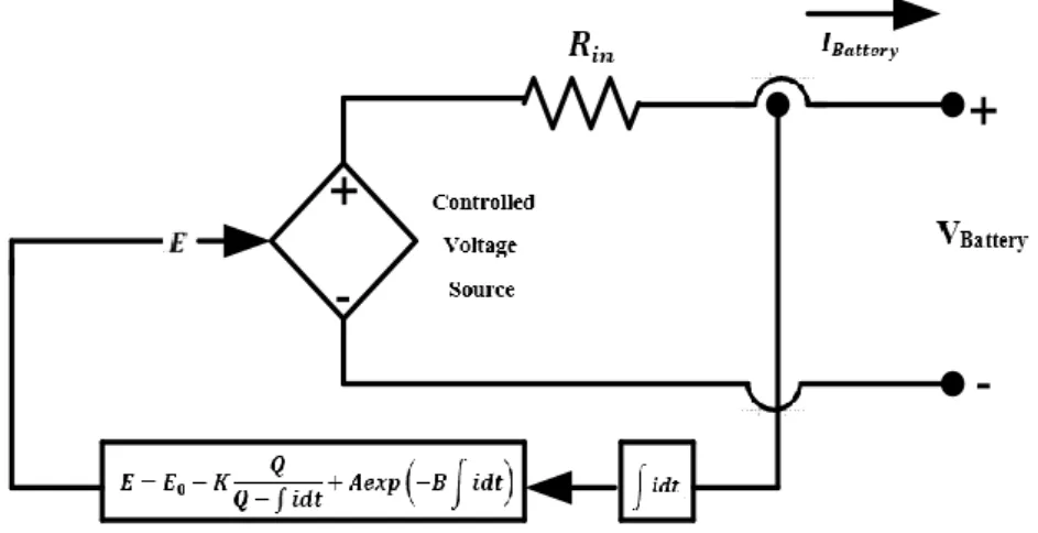
3.5. MATHEMATICAL MODELING OF BATTERY ... 41
3.6. MATHEMATICAL MODELING OF TRANSFORMER... 42
3.7. MATHEMATICAL MODELING OF GENERATOR ... 44
PART 4 ... 46
CONTROL AND OPERATION OF MICROGRID BASED ON ... 46
MULTI-AGENT SYSTEM ... 46
4.1. MICROGRID CONTROL STRATEGIES ... 46
4.1.1. Centralized Control ... 46
4.1.2. Decentralized Control ... 48
Page
4.2.5. MACSimJX Middleware ... 55
4.3. APPLICATIONS OF MULTI-AGENT SYSTEM IN MICROGRID ... 57
4.3.1. Distributed Control ... 57
4.3.3. Service Restoration ... 60
4.3.4. Optimization ... 60
4.4. MAS BENEFITS AND DRAWBACKS ... 60
PART 5 ... 62
VALIDATION OF OUTCOMES USING CASE STUDIES ... 62
5.1. CASE STUDY 1: FAULT DETECTED, DISTRIBUTED CONTROL, LOAD PROTECTION AND SERVICE RESTORATION ... 62
5.1.1. Fault Scenarios ... 63
5.1.2. MAS Structure of KBU MG ... 64
5.1.3. Microgrid Simulation Circuit Description ... 66
5.1.4. Simulation Results and Discussion ... 67
5.2. CASE STUDY 2: OPTIMIZATION OF MICROGRID ... 70
5.2.2. Implementation of Agents ... 74
5.2.3. Simulation Results and Analysis ... 74
PART 6 ... 97 CONCLUSION ... 97 6.1. CONTRIBUTIONS OF THESIS ... 98 6.2. RECOMMENDATIONS ... 100 REFERENCES ... 101 APPENDIX A ... 110 APPENDIX B ... 118 RESUME ... 120
LIST OF FIGURES
Page
Figure 2.1. Example of MG structure. ... 15
Figure 2.2. Location of point common coupling (PCC). ... 18
Figure 2.3. A static switch and microgrid scheme ... 18
Figure 2.4. A static switch consists. ... 19
Figure 2.5. Microgrid classification. ... 20
Figure 2.6. Scheme of a DC microgrid ... 21
Figure 2.7. AC microgrid system ... 23
Figure 2.8. Hybrid microgrid system. ... 24
Figure 2.9. Hierarchical control levels of a microgrid. ... 25
Figure 2.10. PQ control mode with active and reactive power references. ... 27
Figure 2.11. Voltage and current control loops in voltage control mode ... 27
Figure 2.12. Secondary and tertiary controls. ... 29
Figure 2.13. Block diagram of PLL. ... 30
Figure 3.1. Architecture of Engineering Faculty of Karabuk University (KBU) microgrid. ... 32
Figure 3.2. Solar cell equivalent circuit ... 33
Figure 3.3. Equivalent circuit of boost converter. ... 34
Figure 3.4. Boost converter circuit when the switch is a turn-on. ... 34
Figure 3.5. Boost converter circuit when the switch is a turn-off. ... 35
Figure 3.6. Incremental conductance technique on a P-V curve of solar module. .. 36
Figure 3.7. A flow chart of an incremental algorithm. ... 38
Figure 3.8. Perturb and observe technique ... 39
Figure 3.9. Perturb and observe flowchart. ... 40
Figure 3.10. Equivalent circuit of three-phase inverter... 41
Figure 3.11. Modeling of a battery... 42
Page
Figure 4.4. FIPA compliant agent platform. ... 53
Figure 4.5. JADE platform ... 54
Figure 4.6. MACSimJX structure ... 56
Figure 4.7. A fully model of MACSimJX ... 56
Figure 4.8. MAS architecture ... 58
Figure 4.9. Fault detection and location by three-level MAS hierarchy ... 59
Figure 5.1. Sniffer agent GUI. ... 63
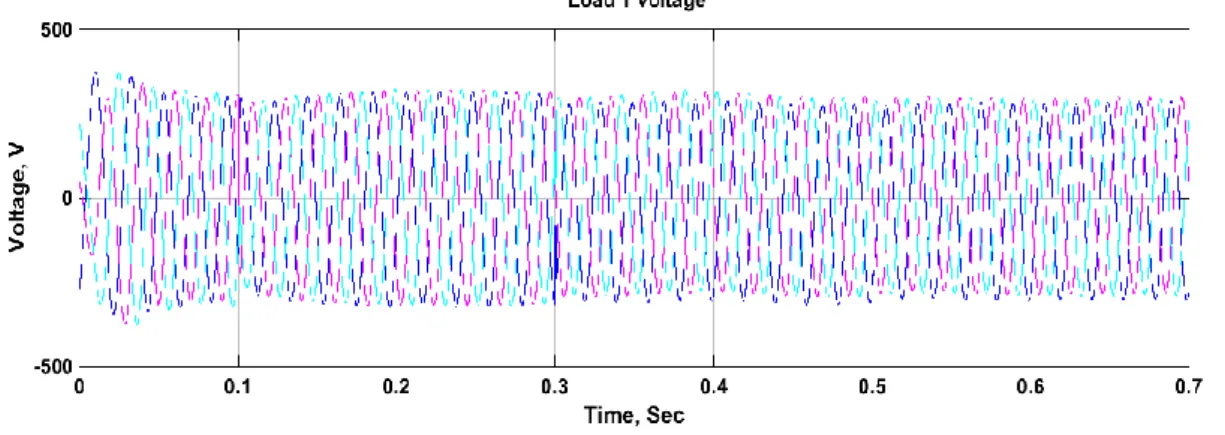
Figure 5.2. Critical load 1 voltage... 64
Figure 5.3. Engineering faculty of KBU MG and MAS control. ... 65
Figure 5.4. Behavior of control agent. ... 66
Figure 5.5. Power of critical load 1. ... 67
Figure 5.6. Power of critical load 2. ... 67
Figure 5.7. Power of non-critical load. ... 68
Figure 5.8. Control signals of control agent... 68
Figure 5.9. Control signals of DER agent. ... 69
Figure 5.10. Critical load 2 voltage... 69
Figure 5.11. Non-critical load voltage. ... 70
Figure 5.12. MAS architecture. ... 72
Figure 5.13. Operation of microgrid depending on the suggested management algorithm. ... 73
Figure 5.14. Communication and interaction among agents. ... 75
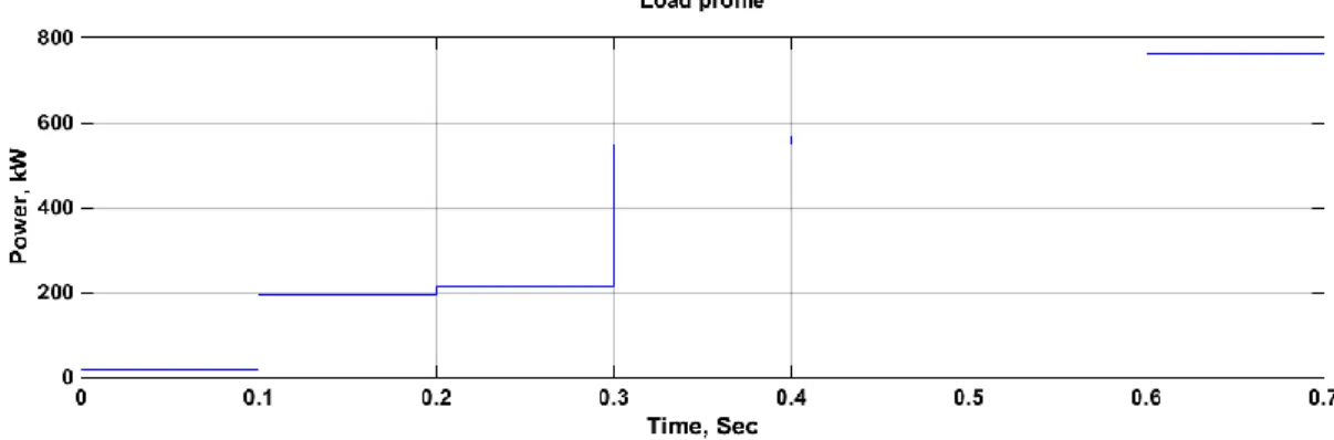
Figure 5.15. Load profile setting 1 of the system. ... 76
Figure 5.16. Load power of the system. ... 76
Figure 5.17. Power generation of the system. ... 77
Figure 5.18. Balance power of PV panels+generator+main grid. ... 77
Figure 5.19. Efficiency of the system. ... 78
Figure 5.20. Control signals of PV panels. ... 78
Figure 5.21. Control signals of the generator. ... 80
Figure 5.22. Control signals of the main grid. ... 80
Figure 5.23. a. The instantaneous voltage across load 1. ... 82
Figure 5.23. b. The instantaneous current through load 1. ... 83
Figure 5.23. c. The actual power for load 1. ... 85
Figure 5.24. a. The instantaneous voltage across load 2. ... 82
Page
Figure 5.24. c. The actual power for load 2. ... 85
Figure 5.25. a. The instantaneous voltage across load 3. ... 82
Figure 5.25. b. The instantaneous current through load 3. ... 83
Figure 5.25. c. The actual power for load 3. ... 85
Figure 5.26. Load profile setting 2 of the system. ... 87
Figure 5.27. Load power 2 of the system. ... 87
Figure 5.28. Power generation 2 of the system. ... 87
Figure 5.29. Balance power 2 of PV+generator+main grid. ... 88
Figure 5.30. Efficiency 2 of the system. ... 88
Figure 5.31. Control signals 2 of PV panels. ... 90
Figure 5.32. Control signals 2 of the generator. ... 90
Figure 5.33. Control signals 2 of the main grid. ... 90
Figure 5.34. a. The instantaneous voltage 2 across load 1. ... 92
Figure 5.34. b. The instantaneous current 2 through load 1. ... 94
Figure 5.34. c. The actual power 2 for load 1. ... 94
Figure 5.35. a. The instantaneous voltage 2 across load 2. ... 95
Figure 5.35. b. The instantaneous current 2 through load 2. ... 96
Figure 5.35. c. The actual power 2 for load 2. ... 96
Figure 5.36. a. The instantaneous voltage 2 across load 3. ... 96
Figure 5.36. b. The instantaneous current 2 through load 3. ... 97
Figure 5.36. c. The actual power 2 for load 3. ... 97
Figure Appendix A.1. Scheme distribution of electrical power for Karabuk University. ... 111
Figure Appendix A.2. Scheme of TR-6 structure loads distribution. ... 115
Figure Appendix A.3. Microgrid model in MATLAB/Simulink. ... 116
LIST OF TABLES
Page
Table 2.1. DERs characteristics. ... 16
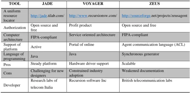
Table 4.1. JADE, ZEUS and VOYAGER multi-agent system development platforms. ... 54
Table 5.1. Characteristics of KBU MG component. ... 65
Table 5.2. Load profile setting 1. ... 76
Table 5.3. Load profile setting 2. ... 87
Table 5.4. Operation modes of the microgrid during different loads. ... 79
Table 5.5. Microgrid operation modes during different dynamical loads. ... 90
Table Appendix A.1. Specifications of transformer in the substation of Karabuk University. ... 111
Table Appendix A.2. Specifications of Karabuk University distribution center transformer (TR6). ... 112
Table Appendix A.3. PV cell FLM-310P-72 specifications. ... 112
Table Appendix A.4. Thermal characteristics of PV cell FLM-310P-72. ... 112
Table Appendix A.5. Xtender XTM 3500-24 inverter specifications. ... 113
Table Appendix A.6. Discharge current at V=1.83 V/cell of battery MUTLU 6OPzS-300. ... 114
Table Appendix A.7. Discharge current at V=1.80 V/cell of battery MUTLU 6OPzS-300. ... 114
Table Appendix A.8. Discharge current at V=1.75 V/cell of battery MUTLU 6OPzS-300. ... 114
Table Appendix A.9. Discharge current at V=1.70 V/cell of battery MUTLU 6OPzS-300. ... 114
SYMBOLS AND ABBREVITIONS INDEX
SYMBOLS
𝑃 : active power
𝑄 : reactive power
𝑖𝑝 : the active current output of the converter
iq : the reactive current output of the converter
TR : transformer
𝜔 : angular frequency
𝐾𝑜 : gain coefficient
𝐼𝑝𝑣 : photovoltaic current
𝐼𝐷 : diode current
𝐼0 : reverse saturated current
𝑘 : Boltzmann constant 𝑞 : electron charge C : capacitance L : inductance 𝑅 : resistance 𝐼 : current 𝑉 : voltage D : duty cycle 𝑉𝐵𝑎𝑡𝑡𝑒𝑟𝑦 : battery voltage
𝑅𝑖𝑛 : battery internal resistance
ø : leakage flux
𝑁1 : primary winding
ABBREVIATIONS
MG : Microgrid
MAS : Multi-Agent System
DER : Distributed Energy Resource MACSim
JX
: Multi agent control simulation Jade extension
FIPA : Foundation for Intelligent Physical Agents
GA : Generation Agent
LA : Load Agent
SCADA : Supervisory Control and Data Acquisition
DC : Direct Current
AC : Alternative Current
MPPT : Maximum Power Point Tracking
DOE : Department of Energy
CRS : Congressional Research Service
LV : Low Voltage
CHP : Combined Heat and Power
SS : Static Switch
EMS : Energy Management System
AGC : Automatic Generation Control
PCC : Point Common Coupling
DG : Distributed Generation
IGBT : Insulated-Gate Bipolar Transistor SCR : Silicon Controlled Rectifier
PLL : Phase Locked Loop
AMS : Agent Management System
ACC : Agent Communication Channel
ACL : Agent Communication Language
DF : Directory Facilitator
AID : Agent Identifier
PV GCM IM RGC GUI KBU : : : : : : Photovoltaic Grid-Connected Mode Island mode
Restoring to Grid-Connected Mode Graphical User Interface
PART 1
INTRODUCTION
The increase in environmental consciousness and rising fuel prices have created an emerging trend of distributed energy resources (DERs) at the electrical distribution networks. DERs may be either sustainable energy resources or traditional units. DERs are typically used in applications that involve standby network support power and independent operation [1].
Moreover, in order to reduce consumers' carbon footprints, more attention has been given to the utilize of renewable technologies in recent years. All those reasons have stimulated considerable interest in microgrid research. With increasing of DERs penetration to power system, mostly to MV/LV distribution network power systems have to an active distribution system with involving consumers to take a point in management of power flow, etc [2,3]. The present power systems are expected to move from passive to more active power systems which will lead to difficulties in stability problems and managing power flow within the network [4,5]. Moreover, for the successful operation of microgrids, the integration of DERs has become an important side of other technical and operational difficulties faced [6].
If the central control approach is used in control active networks where there is bi-directionally power flow inside the network, difficulties may be faced. Although the central approach has been successful in managing traditional power systems operations. Centralized control of several distributed energy resources at distribution voltage levels can be problematic, as they are not feasible to implement economically, which requires other alternative strategies to the management of emerging DERs. A variety of distributed/decentralized approaches have been suggested to improve manage operations of the power system with the merging of a number of DERs at distribution voltage levels. It varies from hierarchical to a completely decentralized
structure. Furthermore, the distributed/ decentralized approach adds many merits like future power system expansion potential, support for plug and play capabilities, increased system reliability, lower infrastructure costs, and reduced computational load on a central server. By this way, the decentralized approach is expected to overcome the limitations of the centralized approach and in the future adequately manage MG operations when more DERs are expected to merge with the current networks.
1.1. MOTIVATION OF THE THESIS
Conventional power systems generally allow power flows in one-way, and it accommodates just client loads but over the last few years, many reasons have urged experts to highlight microgrid schemes. Some motives, which encourage microgrids include:
Reduction in carbon dioxide and other gaseous emissions. The efficiency of energy or using energy in a rational way. Cancellation of restrictions or policy of competition. Diversity in energy sources.
Microgrid integrates DERs, flexible loads and storage devices in a local distribution grid. Also, it operates in a grid-connected mode or in an island mode. The management of power and the available micro-sources’ coordination control takes place through the microgrid.
Control and power flow management are needful to secure the stable and seamless operation of the MGs because of the expected increase in the penetration of DERs at the distribution networks level. Nevertheless, conventional centralized approaches for control proved to be insufficient to deal with the widespread of DERs because of the absence of expandability and flexibility [6]. Furthermore, central control was first used
complexity will be introduced to the central control supervisor and it will need to increase costs for the communication substructure.
Likewise, as the energy industry moves towards decentralization, distribution networks and energy market operations are becoming increasingly complex [9]. Integrate DERs at the distribution voltage levels will cause the direction of the power flow inside the power system network to change from a passive to an active network. Thus, Supervisory Control and Data Acquisition (SCADA) which is a centralized control system was primarily designed for conventional networks, may be insufficient to deal with complex control decisions and the proliferation of distributed energy resources. Furthermore, the suppositions applied to traditional power systems may not apply to active distributed systems that increase the difficulties in the operation of the microgrids [10]. The main issues related to the merging of DERs are shown below [11,12].
The need to send and schedule DERs under demand and supply uncertainties. Control and collaboration and which are achieved and distributed with minimum
data exchange with the central control unit.
Standards communication protocols like MACSimJX.
By providing a common communication interface to the agent platform in the distributed system, many of the above mentioned problems can be solved [13]. This can be accomplished by MAS, which is widely recommended as a convenient approach for controlling and managing distributed systems since it can more easily allocate complex tasks into simpler in order to perform its goals [14,15]. Applications of MAS in MG extend to include distributed generation control, coordination of control schemes, optimization microgrid operation, fault protection strategies and power flow management in real-time applications [16].
MAS is a decentralized form of control that displays distributed intelligence using software agents for communicating, negotiating, and optimizing microgrid operations. Unlike the centralized approach, MAS utilizes an ascendant approach to optimize and manage microgrid operations thus minimizing the communication and complexity of
the microgrid. The main motivation to propose MAS in power systems is mainly due to its ingrained benefits, such as expandability, flexibility, autonomy, and other factors, as well as reducing the complexity of problems. Consequently, the motivation of the study is to design and develop an agent-based distributed control strategy to control and optimize microgrid operations.
1.2. THE PURPOSE OF THE THESIS
The purpose of this study is to design and develop multi-agent system based control of Karabuk university microgrid. To execute this purpose the following objectives are determined:
Modeling and simulation Karabuk microgrid.
Development of Multi-agent system (MAS) using JADE-platform in compliance with the specifications of the Foundation for Intelligent Physical Agents (FIPA).
Design and development of the MAS architecture to control of Karabuk university microgrid.
Protection and restoration of KBU MG based on MAS. Optimization of KBU MG based on MAS.
Transmit control signals at a real-time to the DERs and loads for regulating their power set points.
1.3. METHODOLOGY OF THE THESIS
The focus of this dissertation is to design and develop MAS in the context of a MG. The developed MAS can perform the tasks of isolating the MG from main grid when the main grid failure is detected, protecting critical loads, implementing load shedding for non-critical loads, service restoration and optimizing the operation of a microgrid.
Design of the MAS architecture. Development of the MAS architecture.
Connect of the microgrid simulation and the MAS architecture.
Simulate agents' coordination and interaction based on different agents' targets. Transmit control signals at a real-time to the DERs and loads for regulating their
power set points.
The MG is simulated in MATLAB/Simulink program and the MAS communicates with MATLAB / Simulink simulations via MACSimJX protocol. For assessing the performance of the agent-based control scheme for microgrids, the output active power, voltage and current waveforms for the loads and DERs will be analyzed.
1.4. LITERATURE REVIEW
According to experts, microgrids are increasingly becoming of the most significant power generation systems. It is a concept that merges several micro sources without letting the main grid operations disrupted. It is possible to connect the energy storage systems with either AC or DC microgrids. DC sources and loads are linked with DC networks, while the AC loads and sources are linked to the AC networks [17].
The electrical protection of the microgrid must be expanded to include both MG operation modes (grid-connected/ island modes). In case of a fault is detected in the main grid, the MG is isolated from the main grid, and must regulate its voltage and frequency, compensate the lost power for loads, especially for critical loads by distributed energy resources [18].
As a result of the huge development of the microgrids which contain a number of sensors and actuators associated with different devices within it to implement intelligent and autonomous decisions. The multi-agent system has drawn compelling attention in the current days on account of its ability to improve microgrid efficiency, decrease operation cost of generation units [19].
In Ref [20, 21], the authors describe the agent as an entity that can: take action in an environment, work with other agents to fulfill its goals, react to the changes in the environment. MAS consists of: an environment, objectives, agents, relations, which represent connections among agents and their objectives and operations, which are agents' tasks.
From Ref [22] we can understand the basic notions and properties of the entities which are associated with MAS, in addition, the possible merits of MAS in applications of power system.
In Ref [24], the authors describe the agent with several characteristics: autonomous- the capability to work with no direct intervention from human or devices, with specific control over its acts and decisions, social ability- the agents can communicate with humans and other agents by utilizing communication language to achieve their aims, reactivity- the agents can react to alterations in their environment at an appropriate time and pro-activeness- the agents have the initiative for exhibiting aims-oriented behavior.
The authors in Ref [25] submit the MAS as a group of agents that communicate with each other to resolve a complex problem in which a single agent can’t solve it. The authors classify MAS architecture as the following: centralized architecture, distributed architecture and hierarchical architecture. In a centralized structure, there is no communication between agents. A distributed structure consists of local agents are responsible for elements of the network. The local agents communicate with each other to detect the overall information of the system. In a hierarchical structure, some agents have power over the acts of other agents.
The authors in Ref [26, 27] classify the agents into two categories: reactive agents and cognitive agents. Cognitive agents are more intelligent and have communication abilities. Cognitive agents work as a central control unit that works with reactive agents and controls operations of non-critical loads. In case of a shortage of energy, the central control unit disconnects non-critical loads and reactive agents execute some operations that not require decisions from a central controller.
In Ref [28], the authors submit a distributed system of self-arranging. This distributed system consists of three agents are power agent, power storage agent and load agent. Each agent records and sends its capabilities to a directory, where other agents can assess and demand services. The load Agent is responsible for search about available agents of the power source and selecting offers for power supply. Power agents and power storage agents interact with each other to schedule storage cases.
In Ref [29], the authors implement a framework of MAS consists of 3 layers. The top layer agent oversees on power consumers and suppliers data and isolates loads in
emergency cases. The agents in the middle layer adjust energy-producing sources in the system with the loads in batteries' status. The lower agent is responsible for the communication with the upper layer to receive the data table, orders to connect or isolate from the main grid as well as follow power data from the MG.
In Ref [30], the authors design a MAS framework that includes two levels (upper and lower level) where the agent in the upper level is in charge of providing the main substructure and services, the agents in the lower level are responsible for power supply and demand for power.
In Ref [31], the authors propose a MAS comprises of three agent control agent, distributed energy resource agent and load agent. The control agent is responsible for control a point common coupling (PCC). Distributed energy resource agent is in charge of interchange data among distributed generations such as communication status, power estimation and available energy sources. The load agent observes and controls the loads.
The authors in Ref [32, 33] use a multi-agent learning algorithm to promote the transition to the island mode. This algorithm uses the notion of layered learning. The notion of layered learning is utilized to collect orders and interactions of the agents according to their capability to change the environment and in the end the agents coordinate to achieve their aims.
In Ref [34], the authors propose an approach to manage and control the power of microgrid in real-time. This approach has been used to improve the operation of microgrid based on demand for power, fuel cost, gas emissions and loads.
In Ref [35], the authors propose a control algorithm contains a smart connection agent is utilized to isolate microgrid from the main grid smoothly. This is utilized to increase the microgrid efficiency in the case of transient voltages.
The authors in Ref [36] assign agents to generation units (GAs) and loads (LAs). LAs specify the unit price for the power needed. The task of GAs are selling the produced power at a price higher than the cost of production.
In Ref [37], the authors consider the conventional power system with a radial flow of power undergoes to the penetration of distributed energy resources that are very volatile, nonlinearities, dynamically changing and difficult to predict with certainly so the traditional protection schemes insufficient.
According to Ref [38] microgrid protection must cover both MG operation modes. when upstream blackouts are revealed, the MG is isolated from the main grid and must adjust its produced and consumed power, frequency and voltage to ensure stable operation.
In Ref [39], the authors develop A MAS comprises of three layers: recloser agents layer, zonal agents layer and switch agents layer. The three layers of agents interact with each other to determine and disconnect faults in a MG based on values and direction of the current during the fault. Recloser agents observe the case of reclosers at each substation. Each zonal agent has a switch agent associated with that zone. When a fault happens in the power system network, recloser agents send signals to zonal agents that are connected to switch agents. Each switch agent inspects its zone to isolate it in case of fault exist.
In Ref [40], the authors suggest a multi-agent system architecture that achieves a balance between the objectives of microgrid and demands. During normal operation of the microgrid, agents secure power flow for critical loads at all times in addition if there is extra power, they will export it to other microgrids. In an emergency case, the agents start to disconnect non-critical loads and request extra power.
The authors in Ref [41] submit a MAS architecture consists of three levels to overcome the permanent constraints of the microgrid (balance of active power and power flow). After a fault occurred, the agents in the lower and medium levels communicate with
each other to calculate the available power and demand for power. The agents in the higher level supervise protocols of communication.
In Ref [42], the authors use wireless techniques to exchange information between agents inside the microgrid to service restoration to the grid-connected mode after the fault is cleared.
The authors in Ref [43] design a MAS where each agent is responsible for local knowledge for one node in the network and the agent can access the global information by local communication between agents. In this way, the agent is able to take synchronized load restoration decisions based on global information discovered by local communication between agents.
The authors in Ref [44, 45] develop a MAS controller for optimizing operations of the microgrid. The generations and loads in the microgrid are variety wherefore it is necessary, management these units efficiently to achieve the desired economic benefits from the microgrid.
In Ref [46], the authors use a MAS is capable to observe distributed energy resources and control power flow. The produced power is maximized based on the cost of production and distributed generation constraints.
1.4. THESIS STRUCTURE
This dissertation is structured in six chapters as follows. Chapter 1 presents an introduction to the microgrid. The motivation of the thesis, as well as objectives and methodology are also introduced. It also provides the literature review on applications of MASs in microgrid operations and the structure of the thesis.
Chapter 3 provides mathematical modeling of Karabuk University microgrid components included PV cell mathematical modeling, DC/DC boost converter, three-phase inverter, maximum power point tracking, battery, three-three-phase transformer and generator.
Chapter 4 submits a control and operation of microgrid based on MAS, microgrid control strategies and structure of the multi-agent system. It also presents applications of a multi-agent system in microgrid and multi-agent system benefits and constraints.
Chapter 5 provides a suggested MAS approaches for applications of MAS in a microgrid. The effectiveness of the proposed approaches was verified by case studies. The outcomes from case studies display the validation in employing a MAS to implement arranged and cooperated actions between its agents to achieve the desired aims of the system.
Chapter 6 offers a conclusion, contributions of this study and recommendations for future work on MASs researches in the context of distributed operations of the microgrid.
PART 2
MICROGRID OVERVIEW
According to experts, microgrids are increasingly becoming one of the most significant power production and management system for the future of the power systems. It is a concept that merges several micro sources without letting the main grid operations disrupted. It is possible to connect the energy storage systems with either AC or DC microgrids. DC sources and loads are linked with DC networks, while the AC loads and sources are linked to the AC networks [47].
2.1. MICROGRID DEFINITION
During the current period, many research organizations have presented several definitions of a microgrid in different reports. The following are some important descriptions of a microgrid:
The US Department of Energy has defined the MG as [48]:
A MG is a localized power network that integrates the distributed energy resources (DERs) with certain local flexible loads, which operate in a deliberate island mode or in parallel with the grid to offer high flexibility and reliability to face grid troubles. This integrated distribution system helps to address the power requirement in places with power supply and distribution limitations that mostly include remote sites.
The Microgrid has been defined by the Congressional Research Service (CRS) [49], and that definition is slightly different as compared to the one, which is given above:
use natural gas combustion engine (that generates hot water, electrical power using the water), or fuel cells, diesel generators, or sustainable energy. Microgrids are used for fulfilling the electric supplies of research centers, data centers, plants, medical centers, military bases, and populations located in far-flung areas.
Another definition has been submitted by European research projects [50, 51]:
A Microgrid comprises low voltage (LV) distribution systems, which distribute energy resources (wind turbines, small generators, PV cells, etc.) in addition to storage units like batteries, flywheels, and supercapacitors as well as with elastic loads. Microgrid systems have two modes of operation in a non-autonomous way if connected to the main grid, or in an independent way if isolated from the grid. Integrate micro sources with the power network after coordinating their responsibilities can be boosted benefits to the whole system.
According to the previous definitions, the microgrid features include:
Microgrid integrates DERs, flexible loads and storage devices in a local distribution grid.
A microgrid can work in a grid-connected mode or in an island mode.
The management of power and the available micro-sources’ coordination control takes place through the microgrid.
2.2. MICROGRIDS REASONS
Conventional large power grids offer several advantages. Huge generating stations are usually economical and not need a large number of human resources to its operated. The network of interconnected high voltage transmission allows reducing demand for generators. It is now possible to generate economical electricity and transport it to long distances with limited electrical line losses. A distribution network generally allows one-way power flows, and it accommodates just client loads but over the last few years, many reasons have urged experts to highlight microgrid schemes [52]. Some policy motives, which encourage microgrids include:
Limitation of carbon dioxide and other gaseous emissions. The efficiency of energy or using energy in a rational way. Cancellation of restrictions or policy of competition. Diversity in energy sources.
Some other reasons have mentioned in Ref [53, 54] but with more emphasis on the following considerations:
Modular generating plants’ availability.
Possibility to find locations for micro-generators. Limited building times and low cost of capital.
The location of generating may be near to the load which may decrease transmission costs.
Microgrids’ technical influence on a distribution system. Changes in network voltage as well as regulation.
2.3. BASIC ARCHITECTURE OF MICROGRID
Figure 2.1 is illustrated structure of the microgrid system. It clearly indicates that a microgrid architecture comprises of distributed generation (DG) resource, distribution and storage systems, and control/communication systems [55].
Figure 2.1. Example of MG structure [55].
2.3.1. Distributed Generation (DG) Sources
Numerous industrial technologies use renewable energy resources because it depends on non-depletable sources such as the wind, the light of the sun and underground heat.
Distributed generation systems, which are added to the microgrid, include certain emerging technologies including wind turbines, solar cells PVs, small hydropower generators, combined heat and power CHP and synchronous generators as well as single-phase and three-phase induction generators [56].
Distributed energy resources and storage devices consist of several modules can be installed in a brief time to become part of the power network.
Some typical characteristics of the DERs are shown in Table 2.1.
Table 2.1. DERs characteristics [57, 58].
CHARACTERISTICS WIND PV CELL MICROHYDRO GENERATOR CHP
Possibility of Implementation Depended on Geographical Location Depended on Geographical Location Depended on Geographical Location
At any Time Based on Source
Output of Power AC DC AC AC AC
Gaseous Emissions None None None High Based on
Source Possibility of Control Not
Controllable Not Controllable
Not Controllable Controllable Based on Source Interface AC-DC-AC Converters DC-AC-DC Converters Induction Generator None Synchronous Generator 2.3.2. Storage Systems
The effective operation for microgrid requires to add storage units to achieve a power balance between generated power and demand for power in the short-term. Lasseter [28] concluded in his research that the system that has many DERs, which are designed for operation in the island mode, must have some storage devices for assuring the energy balance. Microturbines and fuel cells have large time constants perform within the 10-200s range so storage systems are significant for power balance after large load changes or system disturbance [59]. When sudden changes take place in the system, the storage devices can work as sources of AC voltage by using inverters. Since they have physical limitations, their capacity for energy storage is limited. The backup energy-storage apparatuses must be added to the microgrid system because they give numerous merits such as improvement of power quality, smoothing the sustainable power resource’s discontinuity, assure a continuous supply of power, and empowering auxiliary services such as regulation of voltage and frequency in operation of microgrid. Some appropriate storage devices, which can be added to a microgrid system, are flywheels, batteries, and super capacitors [38].
2.3.3. Distribution Network Systems
There are three classes of a distribution network in a microgrid [60]:
DC Line: Majority of the DERs generate DC voltage; so, they have no power quality issues, investigation on DC microgrid system is gaining more significance. However, most of the loads are AC loads; therefore, the DC distribution systems are still not common yet.
50/60 AC Line: Can be called line frequency. Most of the microgrids are line-frequency microgrids. The DERs are linked in the microgrid to a common bus. The DC current emerging from distributed energy resources is sent to 50Hz AC through an appropriate inverter and then sent to the load side.
High Frequency AC (HFAC): Several methods are available for connecting DERs in a microgrid system. Utilizing HFAC for transferring energy in the microgrid is still a new concept and it is still in the development stage. The DERs are linked in a common bus in HFAC microgrids. The DERs’ power generation transforms into AC 500Hz through power electronics devices and is sent to the load side, where an AC/AC converter again converts it into 50Hz AC. This load is linked to the distribution network, which results in effective interaction between the distribution network and the microgrid. The harmonics of higher order are filtered at a higher frequency, which limits the active and reactive power problems. HFAC has some issues such as it increases power losses and raises line reactance [60].
2.3.4. Loads
The loads represent the components which consume power including lighting devices, gadgets, industrial loads, and commercial equipment, etc. Loads in microgrid can be categorized into critical and non-critical loads. Critical loads represent loads in which power must be saved with high goodness and dependability, and so cannot be disconnected while non-critical loads represent loads which can be disconnected from power supply for specified time periods to keep up the microgrid working conditions.
2.3.5. Point Common Coupling (PCC)
This point exists in the electric circuit, in which, a MG is linked with the main grid. MGs without a PCC are termed as “confined” MGs because they have remote mechanical destinations. In this case, the interconnection with a primary network is impossible out of technological or financial reasons [61].
Figure 2.2. Location of point common coupling (PCC) [62].
2.3.6. Static Switch (SS)
The static switch links the MG to the main grid.
S
Protection of microgrid by isolating it from the main grid during emergency or maintenance cases is one of the important issues in microgrid applications. The static switch enables the microgrid of connection and disconnection with the main grid.
Main grid MS Load
S
PCC TR AC bus
Controller
Figure 2.4. A static switch consists [63].
2.3.7. Systems of Communication
Systems of communication are very significant in the control and protection of power systems. The methods of basic communication, which are used in the existing microgrid testbeds, include broadband over power line, power-line carrier, lines of telephone, LAN/WAN/Internet (TCP/IP), global system for mobile (GSM) communication, optic fiber, wireless radio communication, WiMAX, Wi-Fi, and ZigBee/IEEE 802.15.4 [56].
2.4. MICROGRID OPERATION MODES
The microgrid operation modes are as follows [64]:
Grid-connected mode: In this mode, a microgrid is linked with the main grid at the point of common coupling. In this mode, the MG receives its partial or total energy from the main grid based on power-sharing. In the case of surplus power, the surplus is sent to the main grid.
Island mode: This mode is executed when the main grid failure occurs, or when there are some routine procedures such as maintenance, the microgrid can
transition to island mode seamlessly; therefore, the microgrid becomes autonomous; so, it is called island mode.
2.5. MG TYPES
Experts have classified microgrids based on operational modes, types, source, scenario and sizes, figure 2.5 illustrated that [65, 66].
Figure 2.5. Microgrid classification [65] .
Based on the type of power, MGs are classified into:
DC microgrids. AC microgrids.
Hybrid AC and DC coupled microgrid.
internet devices. The sources which have DC output are directly linked to DC bus, while the sources which have AC output, are linked with the DC bus by AC/DC converter. Advantages of DC microgrids are as follows:
Few frequency components, which simplify control.
For DC loads not need to AC/DC converter where they can be integrated directly with DC sources thus reducing costs and energy dissipation.
Less line losses in the DC transmission lines in comparison with the AC transmission.
Low cost.
The issues of the DC microgrids are as follows:
Difficult expansion.
Electrical arc is very dangerous during DC breaking.
2.5.2. AC Microgrid
All parts in the AC microgrid system are linked with standard AC voltage of the grid (such as 50Hz, 230/240V) at a point before the local load. This system has the merit of expandability. This type of power system is now popular because it has decentralized power networks. The principal disadvantage for these systems is they need an inverter [68].
The advantages of AC microgrids are:
The dump load (it is an electrical device to store power in case the batteries get full or whenever extra power is no longer needed) is not needed when it is linked to the grid.
It is easier to expand. Circuits are simple.
The AC microgrids have the following disadvantages:
It is required DC/AC inverters which are expensive. Inverter makes it less efficient.
Mostly in distribution system AC microgrid is used. The construction of AC microgrid is obvious in Figure 2.7. In AC microgrids, power storage units and distributed energy resources are linked with an AC bus by power electronics devices. The static switch is used as a control to switch mode from the grid-connected mode to islanded mode and vice versa [69].
Figure 2.7. AC microgrid system [68].
2.5.3. Hybrid AC/DC Microgrid
Experts believe that the hybrid system is a futuristic substitution to the conventional power system that assures the power reliability, store energy and save operational costs because this system merges different renewable energy resources AC and DC.
The hybrid microgrids include the AC and DC MGs features, and both are interconnected to each other by electronic devices (converters). AC DERs and loads are linked to the AC bus whereas DC DERs and loads are linked to the DC bus. Storage units are either connected to the DC or the AC bus. The AC microgrid is connected to the main grid in the normal mode, in which, the main grid supplies power to the whole system and keeps stabilization it. In the islanded mode, a static switch disconnects the AC microgrid from the main grid. All the storage devices and distributed energy resources are installed with a purpose to stabilize the system [70].
An exemplary construction of a hybrid AC/DC MG has been clarified in Figure 2.8, which shows a couple of grids including an AC and a DC grid and both are connected to each other via a bidirectional AC/DC converter. The three-phase AC grid is connected with the main grid by step down transformer and circuit breaker. Both AC loads and AC DERs are linked with the AC grid while the DC DERs are linked with
the DC grid by converters. DC storage units and loads are connected to a DC grid by DC/DC converters [71]. CB AC loads Wind turbine DC loads PV system Micro-turbine Fuel cell Storage system DC link AC bus Bidirectional AC/DC converter
Figure 2.8. Hybrid microgrid system.
2.6. OBJECTIVES OF CONTROL IN AC MICROGRIDS
Microgrids either operate in the island or the grid-connected mode. The suitable control in a microgrid assures economical and stable operation. The microgrid control structure has certain principal roles, which are mentioned below [64, 72-76]:
Frequency and voltage regulation in both the operating modes.
Appropriate distributed energy resources coordination and load sharing. Resynchronizing a MG with the main grid.
Management power flow between the microgrid and the main grid. Optimizing the operational cost of a microgrid.
2.7. CONTROL LEVELS OF AC MICROGRID
The demands that we mentioned in the above paragraph have varying significances; therefore, they require a hierarchical control structure for addressing every requirement at different hierarchical control levels. The hierarchical control levels of a microgrid are primary, secondary, and tertiary controls, which have been exhibited in Figure 2.9.
Tertiary control responsibilities # Optimum operation in both
operation modes
# Control of power flow in grid connected mode
Secodary control responsibilities # Compensating the voltage and
frequency deviation caused by primary control
Primary control responsibilities # voltage and frequency stability
preserving
# Plug and play capability of DGs
Microgrid Main grid Connect F ee d b ac k s ig n al s
2.7.1. Primary Control Level in AC Microgrid
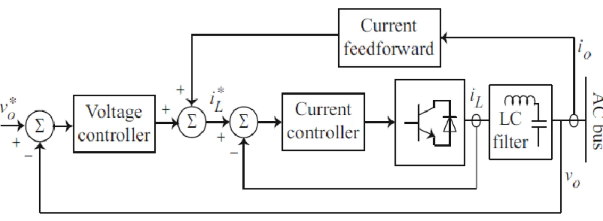
The primary control or the local control level offers the setpoints for control loops (voltage and current) of distributed energy resources.
The purpose of the primary control level includes the following:
To ensure frequency and voltage stability: Right after an islanding event, a microgrid is likely to lose its voltage and frequency stability because there is a mismatch between power generation and consumption.
To provide a plug-and-play capability for distributed energy resources and implement power-sharing among them, which happens without any communication link.
Mitigating circulating currents: Sometimes, two power sources have different voltages, which are connected in parallel, and it is connected to a load in parallel combination. Circulating currents result in overcurrent in the power electronic devices, which may damage the DC-link capacitors.
The primary control level offers the reference points for the current and voltage at real-time of distributed energy resources through active/reactive (PQ) power control mode or voltage control mode. PQ control mode regulates the active and reactive distributed energy resources power delivery in the pre-determined reference points, which are given in Figure 2.10. In this figure we show that H1 control unit regulates the active
power and the DC-link voltage through control the magnitude of the active current output of the converter (ip). H2 control unit adjusts the reactive power output through
Figure 2.10. PQ control mode with active and reactive power references [72].
Figure 2.11 shows the voltage control mode that includes the voltage and current control loops.
Figure 2.11. Voltage and current control loops in voltage control mode [72].
𝑣0∗(𝑠) − 𝑣0(𝑠) = 𝑣𝑒(𝑠) (2.1)
𝑖𝐿∗(𝑠) − 𝑖𝐿(𝑠) = 𝑖𝑒(𝑠) (2.2)
2.7.2 Secondary Control
The primary control level might result in voltage and frequency deviations. Despite the fact that the energy storage units compensate for the mentioned deviations, they
cannot supply power for controlling the load frequency in the long term because of their limited energy capacity. The primary control level is locally implemented at each distributed energy resource. The centralized secondary control restores the frequency and voltage of the microgrid and recompenses the deviations that occur due to primary control [72].
Figure 2.12 illustrates the block diagram of the traditional secondary controls with a centralized structure. As the figure indicates, the microgrid frequency and the terminal voltage of a selected distributed energy resource are compared to their corresponding reference values such as 𝜔𝑟𝑒𝑓 and 𝑉𝑟𝑒𝑓. The individual controllers process error signals, which are given in Equations 2.3, 2.4; so, the resulting signals (𝛿𝜔 and 𝛿𝐸) are transmitted towards the primary control unit of the distributed energy resource for compensating for the voltage and frequency deviations [72, 77].
𝛿𝜔 = 𝐾𝑃𝑤(𝜔𝑟𝑒𝑓 − 𝜔) + 𝐾𝐼𝜔∫(𝜔𝑟𝑒𝑓 − 𝜔) 𝑑𝑡 + ∆𝜔𝑠 (2.3)
𝛿𝐸 = 𝐾𝑃𝐸(𝑉𝑟𝑒𝑓− 𝐸) + 𝐾𝐼𝐸∫(𝑉𝑟𝑒𝑓− 𝐸) 𝑑𝑡 (2.4)
𝐾𝑃𝑤, 𝐾𝐼𝜔, 𝐾𝑃𝐸, and 𝐾𝐼𝐸 represent the controller parameters. An additional term, ∆𝜔𝑠 to
smooth synchronization of the microgrid with the main gird. ∆𝜔𝑠 = 0 in island mode. During the synchronization, a phase-locked loop PLL module calculates ∆𝜔𝑠 .
Σ Islanded Σ Measuring the voltage and frequency in the MG + -+ -ωref E vref ω GE(s) Gω(s) Primary control of first DG Primary control of second DG Primary control of third DG Σ Δωs Microgrid PCC PLL + + PG, QG MEASURMENT Σ Σ GP(s) GQ(s) PG PG ref QG QG ref + + -Islanded Grid-connected vref G ri d -c o n n ec te d ωref Tertiary control Secondary control Main grid
Figure 2.12. Secondary and tertiary controls [72].
Figure 2.13 demonstrates PLL block diagram. Where, the phase comparator/detector creates the phase for every input that generates an error signal 𝑉𝑒(𝑡), which is proportional to the phase differences between two inputs. In this case, 𝐾𝐷 represents
the gain of the phase detector (𝑣 𝑟𝑎𝑑⁄ ).
𝑉𝑒(𝑡) = 𝐾𝐷(∅𝑜𝑢𝑡(𝑡)−∅𝑖𝑛(𝑡)) (2.5)
The low-pass filter deletes high frequency. The voltage is controlled through oscillation frequency. It is compared to the input frequency and controlled until it equal to the input frequencies.
𝜔𝑜𝑢𝑡 = 𝜔𝑜+ 𝐾𝑜𝑉𝑐𝑜𝑛𝑡 (2.6)
Here 𝜔𝑜 represents nominal angular frequency, and 𝐾𝑜 is a gain coefficient (𝑟𝑎𝑑/𝑠/𝑣).
Phase detector Loop filter VCO
Ø
in(t)
Ø
out(t)
ω
in(t)
ω
out(t)
V
contFigure 2.13. Block diagram of PLL [78].
2.7.3 Tertiary Control
The economic operation of the MG and managing power flow among the main grid and MG are responsibilities this level [79]. Grid-connected mode allows the power flow among the main grid and the MG by controlling the frequency and voltage of distributed energy resources. This process is illustrated in Figure 2.12. The measurements of both active and reactive output powers were done for microgrids 𝑃𝐺 and 𝑄𝐺. The mentioned quantities are previously compared to the corresponding
reference values, 𝑃𝑟𝑒𝑓𝐺 and 𝑄𝑟𝑒𝑓𝐺, to get the reference for frequency and voltage, 𝜔𝑟𝑒𝑓 and 𝑣𝑟𝑒𝑓 based on the following Equations:
𝜔𝑟𝑒𝑓 = 𝐾𝑝𝑝(𝑃𝑟𝑒𝑓𝐺 − 𝑃𝐺) + 𝐾𝐼𝑃∫(𝑃𝑟𝑒𝑓𝐺 − 𝑃𝐺) 𝑑𝑡 (2.7)
𝑣𝑟𝑒𝑓 = 𝐾𝑝𝑞(𝑄𝑟𝑒𝑓𝐺 − 𝑄𝐺) + 𝐾𝐼𝑞∫(𝑄𝑟𝑒𝑓𝐺 − 𝑄𝐺) 𝑑𝑡 (2.8)
Here, 𝐾𝑝𝑝, 𝐾𝐼𝑃, 𝐾𝑝𝑞, and 𝐾𝐼𝑞 are controller parameters [72]; 𝜔𝑟𝑒𝑓 and 𝑣𝑟𝑒𝑓 are applied later as the reference values for the secondary control, which is obvious from Equations 2.3 and 2.4.
PART 3
MATHEMATICAL MODELING OF ENGINEERING FACULTY KARABUK UNIVERSITY MICROGRID COMPONENTS
In our work Karabuk University (KBU) campus microgrid is considered as studied research object. KBU consists of eight faculty buildings in the campus. Nowadays, five of eight buildings are installed PV-arrays. For our case study we are selected one building- Engineering faculty.
A distribution network of Engineering faculty of Karabuk University consists of two micro sources (PV panels and generator), interface to connect the PV panels to the network (boost converter, maximum power point tracking (MPPT), batteries and inverter), from the main grid side a step-down transformer. this network also contains three loads, two of them are critical loads and the other is non-critical loads. More details about Karabuk University's microgrid components will be discussed in the following chapters of this thesis.
154/34.5 kV M1 CB1 TR 34.5 kV /0.44kV CB2 B1 Noncritical loads PCC CB4 CB3 CB5 AC DC B2 DC DC PV Battery Critical loads 1 B3 CB6 generator Critical loads 2 MPPT
Figure 3.1. Architecture of Engineering Faculty of Karabuk University (KBU) microgrid.
3.1. MATHEMATICAL MODELING OF PV CELL
The equivalent circuit of solar cell consists of source of current in parallel with a diode. But actually, there is no ideal solar cell, thus a parallel resistance and series resistance are appended to the model as shown in Figure 3.2 [80].
I
pvI
DR
shR
sI
+-V
I
RshFigure 3.2. Solar cell equivalent circuit [16].
𝐼 = 𝐼𝑝𝑣− 𝐼𝐷− 𝐼𝑅𝑠ℎ (3.1)
𝐼𝐷 = 𝐼0(𝑒𝑞𝑣𝑘𝑇𝑑 − 1) (3.2)
Io = reverse saturated current.
𝐼 = 𝐼𝑝𝑣− 𝐼0(𝑒𝑞𝑣𝑘𝑇𝑑− 1) − 𝑣𝑑 𝑅𝑠ℎ (3.3) We have: −𝑣𝑑+ 𝐼𝑅𝑠 + 𝑉 = 0 (3.4) 𝑣𝑑 = 𝐼𝑅𝑠+ 𝑉 (3.5) 𝐼 = 𝐼𝑝𝑣− 𝐼0(𝑒 𝑞𝑣𝑑 𝑘𝑇 − 1) − (𝐼𝑅𝑠+ 𝑉 𝑅𝑠ℎ ) (3.6) k = Constant of Boltzmann = 1.381 ∗ 10−23 𝐽 𝐾 . q = charge of an electron = 1.60217662 ∗ 10−19 𝐶.
3.2. BOOST CONVERTER MATHEMATICAL MODELING
A boost converter (DC/DC) uses to raise PV cell voltage. The main circuit of boost converter consists of inductor, electronic switch, diode, capacity element and load as shown in Figure 3.3 [81-83].
I
LI
OR
C
V
OV
d -+ -+S
Figure 3.3. Equivalent circuit of boost converter.
When the switch is turn-on the boost converter equivalent circuit becomes as Figure 3.4.
I
LV
LR
C
V
OV
d -+ -+ +-Figure 3.4. Boost converter circuit when the switch is a turn-on.
𝑉𝐿(𝑡) = 𝑉𝑑 (3.7)
𝑑𝑖(𝑡)
∆𝑖𝑜𝑛= 𝑡𝑜𝑛∗𝑉𝑑 𝐿 (3.10) 𝐷𝑢𝑡𝑦 𝑐𝑦𝑐𝑙𝑒 (𝐷)% =𝑡𝑜𝑛 𝑇 ∗ 100 (3.11) ∆𝑖𝑜𝑛 = 𝐷 ∗ 𝑇 ∗𝑉𝑑 𝐿 (3.12)
When the switch is turn-off the boost converter equivalent circuit becomes as Figure 3.5.
I
LV
LR
C
V
OV
d -+ -+ +-Figure 3.5. Boost converter circuit when the switch is a turn-off.
𝑉𝐿 = 𝑉𝑑− 𝑉𝑜 (3.13) 𝑑𝑖(𝑡) 𝑑𝑡 = 𝑉𝑑 − 𝑉𝑜 𝐿 (3.14) ∆𝑖𝑜𝑓𝑓 = (𝑇 − 𝑡𝑜𝑛) ∗𝑉𝑑 − 𝑉𝑜 𝐿 (3.15) ∆𝑖𝑜𝑓𝑓 = (𝑇 − 𝑇𝐷) ∗ 𝑉𝑑 − 𝑉𝑜 𝐿 (3.16) At steady state ∆𝑖𝑜𝑛+ ∆𝑖𝑜𝑓𝑓 = 0 (3.17)
𝐷 ∗ 𝑇 ∗𝑉𝑑 𝐿 + (𝑇 − 𝑇𝐷) ∗ 𝑉𝑑− 𝑉𝑜 𝐿 = 0 (3.18) 𝑉𝑜 = 𝑉𝑑 1 − 𝐷 , 𝐷 < 1 (3.19)
3.3. MATHEMATICAL MODELING OF MAXIMUM POWER TRACKING
MPPT is a common technique uses to improve the efficiency of PV cells under all conditions. Many techniques are used to track the MPP like perturb and observe, incremental conductance method, fractional short circuit current, fractional open circuit voltage, neural networks and fuzzy logic. In PV systems the most commonly used techniques to track the MPP are incremental conductance and perturb and observe [84].
3.3.1. Incremental Conductance Technique
This technique uses two sensors at the output terminal of the PV system one to measure voltage and the other to measure the current. The output voltage is controlled based on the MPP voltage. Figure 3.6 shows the incremental conductance technique on a P-V curve of solar module. The derivative of power to the derivative of voltage (𝑑𝑃
𝑑𝑉) is
zero at MPP. On the left side of the MPP the 𝑑𝑃
𝑑𝑉> 0 and on the right side of the MPP
the 𝑑𝑃
![Figure 2.1. Example of MG structure [55].](https://thumb-eu.123doks.com/thumbv2/9libnet/5398434.101928/36.892.174.770.119.703/figure-example-of-mg-structure.webp)
![Figure 4.9. Fault detection and location by three-level MAS hierarchy [39].](https://thumb-eu.123doks.com/thumbv2/9libnet/5398434.101928/80.892.276.679.556.921/figure-fault-detection-location-level-mas-hierarchy.webp)