bois) and with a simple 7ero-dimensional model (disconnected symbols), taking into account both the main capacitance and the capacitance
of the
bottom patch to ground.The
agreement obtained is clearly good over a broad frequency range, thus dem- onstrating the effectiveness of the proposed model.0 IEE 1995
Electronics Letters Online N o . 19950955
2X June I Y Y S
G. Bartclucci, F. Giannini and E. Limiti (Depurfmenr of Elecfronic Enzineering, Unieersity of Roma ‘Tor Vergata , Via Della Rrercu Scientifica, 1.00133 Romo. Italy)
S.P. Marsh (GEC Marconi Materials Technology Ltd., Caswll. Towce.!fer, Norfhampfonshire N N l Z XEQ. United Kingdom)
References
1 GIANNINI, F , BARToLtJCCI. G . and LIMITI. E.: ‘Planar effects in MIM capacitors’,Proc. European GaAs Applications Symp.. Noordwijk. April 1992
2 BARTOLUCCI, G , CIANNINI, F., LIMITI. E , and MARSH, S P : ‘MIM
capacitor modeling: A planar approach’, IEEE Trans., 1995, MTT-
43, (4), pp. 901-903
3 WOLFF. I , and KNOPPIK. N : ’Rectangular and circular microstrip disk capacitors and resonators’, IEE Tram., 1974. MIT-22, (IO). pp. 857-864
Inductorless realisation
of
Chua oscillator
0.
Morgiil
Indexing ferms C‘hua circuit, Chaos
An inductorless realisation of a Chua oscillator. which exhibits chaotic behaviour is presented. This new realisation consists of the Wien bridge oscillator. coupled in parallel with the same nonlinear resistor used in the standard realisation of a Chua osciibator. This new circuit is shown experimentally to also exhibit similar chaotic behaviour.
Introduction: Nonlinear systems may exhibit many types of com- plex behaviour such as chaos, and this complexity has attracted many scientists from various fields (e.g. physics. mathematics, engineering etc.) to study such systems. Since it has been shown that simple electronic circuits may exhibit chaotic behaviour, the study of chaos in nonlinear electronic circuits received a great deal of attention in the last decade. (See IEEE Trans. Circuits Syst., special issue on chaos in nonlinear electronical circuits, Part I , October and November 1993, and Part 2, October 1993). Among such electronic circuits. the Chua oscillator, shown in Fig. I ,
received a great deal of attention since it is quite simple, well-stud- ied pnd can easily be realised in the laboratory using standard electronic components.
RO
R 5 L
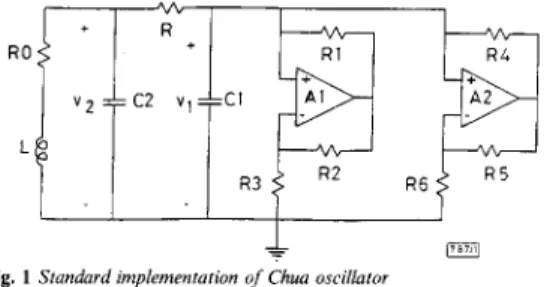
Fig. 1 Standard implementation of Chua oscillator
In Fig. I , the operational amplifiers and the associated resist- ances ( R , , ..., R6) are used to realise the three-segment piecewise lin- ear resistance called a Chua diode, see [I]. The resistor
R,,
represents the internal resistance of the inductor L and is used in the simulations, but not in the actual implementation [I]. For R , = 0 and R,, > 0, this circuit is called a Chua circuit and a Chua oscil- lator, respectively [2]. The resistor R is a potentiometer and can be
used to tune the circuit for observing chaotic behaviour.
For most of the electronic circuits, the inductor IS a less desira- ble circuit element. There are various reasons for this. For exam- ple. inductors are less standard compared to other circuit elements and must
be
prepared separately in most applications, theyare not
as ideal as other circuit elements, and in terms of spatial dimen- sions they are larger than the other circuit elements, unless the inductance is rather small. We present an inductorless realisation of a Chua oscillator. We replace the parallellseries combination ofR,,, L and C, by a Wien-bridge oscillator type circuit and show that this circuit may exhibit chaotic behaviour similar to that of the Chua oscillator.
1 R
I
1 ’ m
i_
I-
Fig. 2 New implementation o/ Chua oscillatorNeiv realisation of Chua oscillator: We consider the circuit shown in Fig. 2. Compared with Fig. I , the parallel/series combination of
R,, L and C, has been replaced by a Wien-bridge oscillator type
circuit. The impedance Z , of the paralleliseries combination of R,,,
L and C, is given by (11
S L
+
Ro s2LC2+
SCZR,+
1 %RIO = RRR!, (2) z1= By using the conditionand assuming that the operational amplifier A3 is ideal and oper- ates in the linear region, it can easily be shown that the impedance Z2 of the corresponding circuit in Fig. 2 (i.e. to the left of 1 - 1’) is
given as
Since the denominator of eqn. 3 is not in the form .r2 +%*,the Wien bridge is not in the oscillatory mode. It can easily be shown that the relevant oscillation condition for this circuit is R,(C,R,
+
CJ,) = C,R,R,,, and this condition can not be satisfied when eqn. 2 holds. Furthermore, eqn. 2 is satisfied when R , = R,, R, = RIPGiven L, C, and R,, if we choose R ,,..., R , , , C, and C, so that eqn. 2 and
R i = R o C3 =C2 C4R7R8
= L
( 4 ) are satisfied, then by comparing eqn. I and eqn. 3 we find that Z, = Z,. Hence, we expect that the circuits in [ I , 21 behave similarly. Since the Chua oscillator in Fig. 1 exhibits chaotic behaviour (e.g. double scroll attractor), we expect similar behaviour for the circuit in Fig. 2. We show that this is indeed the case.E.xperimentu/ results: For the Chua oscillator, chaotic behaviour is observed for the following set of element values:
4
= 12.50, RI = 3.3k0, R, = R, = 22k0, R, = 2.2k0, R, = R, = 2200, C, = IOnF,C2 = IOOnF, L = 18mH, R = 17300, and AI and A2 are opera- tional amplifiers (AD712 or equivalent). These values are taken from [I]. For this circuit, chaotic behaviour can be observed over a relatively large range of R.
For the circuit of Fig. 2, we used the same values for the resis- tors R , , ..., R6 to realise the same three-segment picewise linear resistor. To determine the remaining element values, we first used the values of [I] and eqn. 4. However, by using the resulting ele- ment values, we did not observe chaotic behaviour in our experi- ments. For the following set of element values: R7 =
4
= 3200, R, = R,, = 6800, C, = InF, C, = 15nF and C, = 33nF, we obtained various forms of chaotic behaviour for different values of R in the range 12690 5R
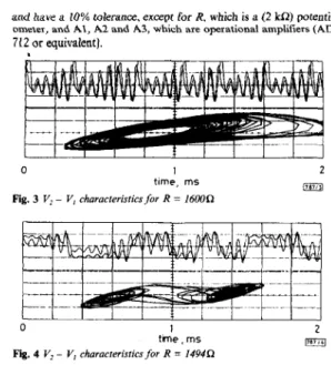
5 16000. In Figs. 3 and 4, the wave- forms of v , and v, and the v2 against vI characteristics are given forR = 1600 and 14940, respectively. All element values are standard
and have a 10% tolerance, except for R, which is a (2
kn)
potenti-712 or equivalent).
ometer, and AI, A2 and A3, which are opesational amplifiers (AD
L l l l l t l l l l l
0 I 2
m
time, rns Fig. 3 V, - V, characferistics for R = 16000
L l l l l i l l l l l
0 1 2
trne , rns Fig. 4 V, - V, characteristics for R = I4940
To obtain these figures, we first observed the v2 ~ v, characteris-
tics on an analogue oscilloscope in the X ~
Y
mode. The samefigure is then obtained on a digitising oscilloscope (HP 54502A). After storing the screen image in the memory of the oscilloscope, the screen is printed on a plotter (HP 7475A) hy using an HB-IB bus. Since the important characteristics indicating chaotic motion are those of v2 - vI, we do not label the signals v , and v,.
We make the following comments:
(i) Figs. 3 and 4 indicate different types of strange attractor. The attractor shown in Fig. 4 is known as a double-scroll attractor, which is a characteristic of the Chua oscillator.
(ii) In our experiments, we observed chaotic behaviour for various values of C,, C, and C, in the range C, 5 I S n F , C, 5 33nF and C, 5 47nF.
(iii) In the experiments described above, the Wien bridge oscillator is not used in the oscillatory mode. It is possible to obtain chaotic behaviour in the proposed circuit when the Wien bridge is used in the oscillatory mode. This makes the proposed circuit very flexible for obtaining different chaotic behaviours.
Conclusions: We have presented an inductorless realisation of a Chua oscillator. We replaced the parallel combination of inductor (with its internal resistance) and capacitor by a Wien-bridge oscil- lator. We shoved by laboratory experiments that with appropriate element values, this new circuit exhibits varied chaotic behaviour including a double scroll attractor. Since this new circuit does not contain an inductor, its practical realisation will occupy less vol- ume than the circuit given in Fig. 1. Hence this new circuit is more suitable for integrated circuit applications. Furthermore, this cir- cuit has more parameters that can be varied, which makes it more flexible for obtaining different chaotic behaviours.
8 IEE 1995
Electronics Letters Online No: 199S097S
0. M o r a l (Bilkent University, Department of Electrical and Electronics Enxineering, MS33, Bikent, Ankara, Turkey)
E-mail: [email protected]
20 June I995
References
1 KENNEDY, M.P.: ‘Three steps to chaos
-
part 2 A Chua’s circuit primer’, IEEE Trans., 1993, C A W , (IO), pp. 657-6752 CHUA,L.O., wu,c.w, HUANG, A , and ZHONG,G.Q.: ‘A universal circuit for studying and generating chaos ~ part 1: Routes to
chaos’, IEEE Trans., 1993, C A W , (IO), pp. 732-745
Algorithm for superstate matrix from trellis
diagram
I.S. Jin, K. Cho and K.C. Whang
Indexing term: Trdis coded modulation
The authors discuss an algorithm for constructing an 9 ‘ x 9
superstate matrix from the s-state trellis diagram and an s x s reduced superstate matrix directly from the s2 x s2 superstate matrix for trellis codes possessing symmetry properties. The algorithm can also be applied to an MTCM scheme, and is especially convenient for trellis codes with a large number of states and/or parallel transitions.
Introduction: The analytical performance of the trellis-coded mod- ulation (TCM) scheme is widely derived by using upper bounds based on the generalised transfer function
T(I).
To findVI),
we must first construct an 9 x s2 superstate (transition) matrix A(I) from the s-state trellis diagram [ I ] . However, for codes with a large number of states and a fully-connected trellis, the procedures become quite complicated and tedious. For codes witha
large number of parallel transitions, such as multiple trellis-coded mod- ulation (MTCM) schemes, the matter becomes even worse.The purpose of this Letter is to provide an algorithm in which the procedure of constructing a superstate matrix for codes with a large number of states and/or parallel transitions is reduced and, as a result, make it easier to evaluate the performance of a TCM scheme.
Inputs of algorithm: The algorithm requires the following inputs: the number of states (s), the size of the M-PSK signal constella- tion (M), the number of parallel transitions ( N J , the number of input bits ( b ) and the multiplicity of the code (k’). The algorithm also needs two input arrays consisting of a description of the trel- lis diagram and the labels of the s2 x Z matrix A(I), which are denoted by trellis[s][s][N,I[b
+
k’] and sm-label[s x s][2], respec- tively. As an example, consider a two-state rate 2/4 (k’ = 2) CPSK MTCM scheme. The trellis diagram for the example is given in [ I ] . For this case, s = 2,M
= 4, Np = 2, b = 2 and k‘ = 2. The array trellis and the array sm-label should be given as follows:static char
trellis[2][2][2][4]
= { { { {0,0,0,0},{0,1,2,2}}, { { { 0 , 0 , 1,3}, {0,1,3, l}}, “state 0+
state 0” “state 0-+
state 1” “state 1 --f state 0” “state 1+
state 1”{
{1,0,0,2},{1,1,2,0}}},
{ {1,0,1,1},{1,1,3,3}} },1;
static int
srnJabel[4][2]
={
1;
io,
01, {I, 11, {0,1), { I , 0)On the basis of the trellis diagram, if there are no possible transi- tions between states (e.g. a half-connected trellis), character ‘ X is assigned to the corresponding positions of the array trellis Algorithm f o r constructing matrix A / I ) : The following algorithm is for the special case when k’ = 2:
(i)frag = 0;
for row = 0 to (s x s - 1) and column = 0 to (s x s - 1) do steps (ii) to (ix);
(ii) select a pair of transitions from the labels of the matrix A(I): GPS = sm-label[row][O]; GNS = sm-label[row][O];
BPS = sm-label[column][ I ] ; BNS = sm-label[column][ I ] ;
(iii) for i , = 0 to (N, - 1) and i2 = 0 to ( N , - I) do steps (iv) to (vi);
(iv) set dH = 0: for j , = 0 to ( 6 - 1) do
bit-G = t r e I l i s [ G P s l [ G N ~ [ i , ] ~ , ] ; bit-B = trellis[BPsl[BNsl[izI[ill; if bit-G or bit-E is character ‘ X , then sm-table[row][column] = ‘X: else if bit-G is not equal to bit-E then dh = dh