Selçuk J. Appl. Math. Selçuk Journal of Vol. 11. No. 2. pp. 13-25, 2010 Applied Mathematics
Unsteady Flow of Micropolar Fluid through a Circular Pipe under a Transverse Magnetic Field with Suction/Injection
J. V. Ramana Murthy1, N. K. Bahali2, D. Srinivasacharya3
Department of Mathematics, National Institute of Technology, Warangal- 506004, A.P., India
e-mail: 1jvrjosyula@ yaho o.co.in,3dsrinivasacharya@ yaho o.com
Received Date: October 20, 2008 Accepted Date: October 19, 2010
Abstract. In this paper, we consider the unsteady flow of an incompressible electrically conducting micropolar fluid through a circular porous pipe subjected to periodic suction/injection at the walls of the tube and in the presence of a transverse magnetic field. Under the Stokesian assumption and using the similarity transformations, the stream function and microrotation components are obtained in terms of Bessel’s functions. The variation of skin friction with respect to micropolar parameters and Hartman’s number, suction parameter are studied and depicted through graphs.
Key words: Micropolar fluid, circular cylinder, MHD, Suction/Injection, Skin friction
2000 Mathematics Subject Classification. 76A05, 76W05. Nomenclature:
Radius of the cylinder _
0 Applied magnetic field
Cross viscosity parameter ( ( + )) _ Electric field _ Current density Microgyration Hartmann number ³ = 0 p ( + )´ Pressure _ Velocity vector Radial distance
Couple stress parameter¡2¢
Time ( ) ( ) Velocity components 0 Entrance velocity 0 Suction velocity Gyration parameter ¡Ω2¢ Electrical conductivity 0 Magnetic permeability Ω Suction frequency
Material constants (viscosity coefficients) _
Microrotation vector
( ) Microrotation component Frequency parameter (Ω0) 1. Introduction
The study of unsteady flow in a porous channel or tubes has received much attention in recent years because of its various applications in biomedical engi-neering as well as in many other engiengi-neering areas such as transpiration cooling gaseous diffusion technology, cooling of rocket etc. The steady flow in a straight channel with porous walls was first studied by Berman [1]. He gave a series so-lution for the laminar two dimensional flow between two parallel porous plates driven by uniform injection and suction. The problem of finding a similarity so-lution, by using an analytic perturbation method, of the steady flow in a straight tube with circular cross section was first treated by Yuan et al [2]. Terrill [3,4] gave an exact solution for the laminar flow in a pipe of circular cross section. The same problem was studied by Tsangaris and Kondaxakis [5] for unsteady wall suction and/injection.
In recent years, the flows of fluids between parallel plates or tubes have re-ceived new attention within the more general context of magnetohydrodynamics (MHD). Terill and Srestha [6] studied the laminar flow between parallel plates in the presence of a magnetic field. Attia and Kotb [7] studied the MHD flow between parallel plates with heat transfer. The study of non-Newtonian fluid flows has gained much attention by the researchers because of their applications in biology, physiology, technology and industry. In addition, the effects of mag-netic field on the non-Newtonian fluid also have great importance in engineering applications; for instance, MHD generators, accelerators, aerodynamics heating, electrostatic precipitation, polymer technology, petroleum industry, purification of crude oil and fluid droplets sprays, plasma studies and geothermal energy excitations etc. El-Sakka and El-Dabe [8] have studied the unsteady MHD flow of elastico-viscous fluid in a circular pipe. Moustafa El-Shahed [9] considered the effect of a transverse magnetic field on the unsteady flow of a generalized second grade fluid through a porous medium in a circular tube. Attia [10] has investigated the unsteady flow of a dusty non-Newtonian Bingham fluid through a circular pipe. Khan et al [11] have obtained an exact solution for the MHD flow of a generalized Oldroyd-B fluid in a circular pipe.
The theory of micropolar fluids initiated by Eringen [12] exhibits some micro-scopic effects arising from the local structure and micro motion of the fluid elements. Further, they can sustain couple stresses and include classical New-tonian fluid as a special case. These fluids can support stress moments and body moments and are influenced by spin inertia. Several investigators have made theoretical study of micropolar fluid flow in the presence of a transverse magnetic field. Kasiviswanathan and Gandhi [13] have studied a class of exact solutions for the MHD flow of a micropolar fluid confined between two infinite, insulated, parallel, non-coaxially rotating disks. Ahmadi and Shahinpoor [14] have studied the criteria for universal stability of the unsteady motion of an in-compressible, electrically conducting linear micropolar fluid. Rama Bhargava et al. [15] have analyzed the effect of temperature dependent heat sources on the fully developed free convection electrically conducting micropolar fluid between two parallel porous vertical plates in a strong cross magnetic field.
In this paper we consider the unsteady flow of an incompressible micropolar fluid through a circular tube with porous wall in the presence of a transverse magnetic field.
2. Formulation of the Problem
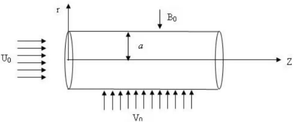
Consider the flow of an incompressible electrically conducting micropolar fluid through a porous circular pipe of radius along the direction of axis of the tube. Assume that there is a periodic suction or injection velocity 0Ω at the wall of the tube. Choose the cylindrical polar coordinate system ( ) with the origin at the center of the tube and z-axis along the axis of the tube. The flow is subjected to a constant magnetic field ¯0perpendicular to the wall and no external electric field is applied. Assume that the magnetic Reynolds number is vary small, so that induced magnetic field and electric field produced by the motion of the electrically conducting fluid are negligible. Under the above assumption and using Stokes approximation the equations governing the incompressible MHD micropolar flow in the absence of body forces and body couples are given by
(1) div ¯ = 0
(2) ¯
= −grad + curl¯ − ( + )curl curl¯ + ¯ × ¯0
(3) ¯
= −2¯ + curl¯ − curl curl¯ + ( + + )grad div¯
where ¯ is the velocity vector, ¯ is the micro rotation vector and is the fluid pressure, and are the fluid density and micro gyration parameter, ¯0 is the
magnetic field and ¯ is the current density. , , , and are the material constants (viscosity coefficients) which satisfy the following inequalities.
(4) 2 + ≥ 0 ≥ 0 3 + + ≥ 0 ≥ ||
The current density ¯, applied magnetic field ¯0and electric field ¯ are related by Maxwell’s equations
(5) curl ¯ = −
¯0
div ¯0= 0 curl ¯0= 0¯ div ¯ = 0 = ( ¯¯ + ¯ × ¯0)
where is Electrical conductivity and 0is magnetic permeability.
Since the flow is symmetric all the quantities are independent of . We choose velocity vector ¯ and micro rotation ¯ in the form
(6) = {( )¯¯ + ( )¯}Ω =¯ ( )
¯ Ω
Substituting Eq. (6) in Eqs.(1) - (3), we get
(7) + + = 0 (8) Ω = − − + ( + ) ( − ) − 2 0 (9) Ω = − + − ( + ) (( − )) − 2 0 (10) Ω = −2 + − + 2 where 2= 2 2 − 1 + 2
2is the Stokes operator. The boundary conditions are
(11) ( ) = 0 ( ) = 0 and ( ) = 0 = ( ) = 0 = 0 at = 0 and () = 0 as → 0 Introducing the following non-dimensional scheme
(12) = ˜ = 0˜ = 0˜ = 0˜ = 02 = ˜ 0
and the stream function ( ) through, (13) ( ) =1 and( ) = − 1
in to the Eqs. (8) - (9) and eliminating pressure from the resulting equations, we get (after dropping tildes)
(14) 2 = −2 + 4 − 22
(15) (2 + ) = 2 + 2
where, = + is the cross viscosity parameter, = 2 is the couple stress parameter, =0
+ is the Suction Reynolds number = Ω
0 is the frequency
parameter, = Ω 2 is the gyration parameter, = 0 q
+ is the Hart-mann number corresponding to micropolar fluid.
From Eq. (14) and Eq. (15) we have
(16) = − 2+ 2122 [ 4 − (21+ 2 2)2] − 2 Substituting in Eq. (14) we get
(17) 2(2− 21)(2− 22) = 0 where
(18) 21+ 22= (2 − ) + 2+ ( + )
(19) 2122= (2 + )(2+ )
3. Solution of the Problem
Following Terril [3], we can write the stream function and microrotation com-ponents as (20) = µ 0 0 − ¶ () and = µ 0 0 − ¶ ()
() and () are functions of to be determined and 0 average entrance velocity.
Substituting Eq. (20) in Eq. (16) and Eq. (18) we get (21) 2(2− 21)(2− 22) = 0 (22) () = − 2+ 2122 [ 4 − (21+ 2 2)2 ] − 2 where 2= 2 2 − 1
The boundary conditions in terms of and are
(23) (1) = 1
0(1) = 0 (1) = 0 (0) = 0 2 = 0 at = 0 and () = 0 as → 0 The general solution of Eq. (21) is
(24) = 1+ 22+ 31(1) + 51(1) + 41(2) + 61(2) where 1 2 3 4 5and 6 are arbitrary constants and 1(1) and 1(1) are modified Bessel functions of the first-order of first and the second kind respectively. Substituting in Eq. (20), we get
(25) = (
2+ − 2
1)[31(1) + 51(1)] +(2+ − 22)[41(2) + 61(2)]] Using the boundary conditions (23) we get
(26) 1= 5= 6= 0 (27) 2+ 1 2[2(1) + 0(1)]3+ 2 2[2(2) + 0(2)]4= −1 (28) 2+ 31(1) + 41(2) = 1 (29) 3(2+ − 21)1(1) + 4(2+ − 22)1(2) = 0 Solving these equations the constants 2 3 4can be obtained.
4. Pressure Distribution
From Eq. (8) and Eq. (9), the non dimensional pressure is given by
(30) = 1 [−( 2+ ) + + 2 ] = (0 0 − ) [−( 2+ )0+ 0+ 2 ] On integrating Eq. (30) and after simplification we have
(31) = −(2+ ) ½ 2 2 + ( 0 0 − ) 2 ¾ 2+ 0 5. Skin Friction
The stress tensor for micropolar fluid is given by
(32) = (− + ¯)+ (2 + )+ (− )
where and 2 are the components of the microrotation vector and the vor-ticity vector respectively, are the components of the rate of strain, is the alternating symbol and comma denotes covariant differentiation.
The shear stress is given by
(33) = V0( + ) 2 ( 0 0 − )(− 2 + )
Hence the coefficient of skin friction (= 202)on the wall of the cylinder = 1 is given by
(34) =
(2+ )
{21(1) + 31(2)} 6. Results and Discussions
The system of equations (26) - (29) is solved using MATHEMATICA and the stream function in Eq. (20) is calculated from Eq.(24). Then the flow pattern is obtained for different times at /4, /2, and 3/2 over a cycle of suction by taking real part of and is shown in Fig.2. As it is expected, the figure shows that the flow is of oscillatory nature over a period 2.
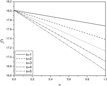
To explicitly see the effects of various parameters like cross viscosity parameter (), couple stress parameter (), suction Reynolds number (Re), magnetic pa-rameter ( ), gyration papa-rameter () and frequency papa-rameter () on the skin
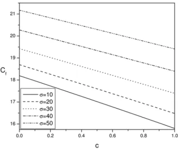
friction (shear stress at the wall), coefficient of skin friction given in Eq. (34) is numerically evaluated and the results are graphically presented in Figs. 3 -7. If 6= 0, then the geometric parameters 1 and 1 are complex which are not conjugate to each other. If one of the values of 1and 2is real, the other value need not be real. Hence the velocity field, microrotation field and skin friction are complex. The real parts of these quantities i.e. when suction is in the form of a cosine oscillation are taken and the skin friction is numerically evaluated. The effect of couple stress parameter on the skin friction is shown in Fig. 3 for = 5 = 04 = 06 = 10 and = 10. It can be observed that as the couple stress parameter increases, the skin friction is decreasing. In the limit as → ∞ (i.e. → 0 and → 0), the governing equations (8-10) reduce to the corresponding equations for a viscous fluid. Hence, viscous fluids have less skin friction compared to that of micropolar fluids. This is expected because of the rotational motion arising from the micromotion of the fluid molecules in micropolar fluids. Similarly as cross viscosity parameter increases the skin friction is decreasing. The variation of skin friction with for different values of is given in Fig. 4 for the values of = 15 = 04 = 06 = 10 and = 10 . It can be seen from this figure that as the gyration parameter increases, the skin friction is decreasing. When increases, radius of the volume element increases or angular velocity of the particle decrease and hence skin friction decreases.
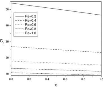
Fig. 5 shows the effect of suction Reynolds number on the skin friction for the values of = 5 = 04 = 15 = 10 and = 10. It is interesting to note that as the suction velocity increases (i.e increases), the skin friction is decreasing. This observation is similar to that of viscous fluids. There is sudden decrease from 58 to 20 in the value of the skin friction when the value of is increased from 02 to 06. Hence the skin friction is very sensitive to the suction Reynolds number.
The effect of the magnetic parameter ( ) on the skin friction is shown in Fig. 6 for the values of = 5 = 04 = 15 = 04 and = 10. It can be noted from this figure that skin friction increases with the increase in magnetic parameter M. This happens because of the imposing of a magnetic field normal to the flow direction. This magnetic field gives rise to a resistive force and slows down the movement of the fluid. The variation of skin friction with frequency parameter is shown in Fig. 7 for = 5 = 04 = 15 = 04 and = 10. It is clear from this figure that the skin friction is increasing with the frequency parameter increases.
7. Conclusions
The flow generated in a circular cylinder due to periodic suction/injection ap-plied on the wall of the tube under a constant magnetic field is considered. It can be noted that applied suction at the surface and the couple stress parame-ter decreases the skin friction. Where as the frequency of suction, the gyration parameter and the magnetic field increases the skin friction.
References
1. Berman A.S., Laminar flow in channels with porous walls, J. App. Phy., Vol 24, pp 1232-1235, 1953
2. Yuan S.W., Finkelstein A.W., Brookyln N.Y., Laminar pipe flow with injection and suction through a porous wall ,Trans ASME, vol.78, pp 719-724, 1956
3. Terril R.M., An exact solution for flow in a porous pipe, ZAMP, Vol.33, pp547-542, 1982,
4. Terril R.M., Laminar flow through a porous tube, J Fluids Eng,Vol.105, pp 303-306, 1983,
5. Tsangaris S., Kondaxakis D., Exact solution for flow in a porous pipe with unsteady wall suction/injection, Comm. in Nonlinear Sci. Num. Simu. Vol. 12 1181—1189, 2007 6. Terril R.M., Shrestha G.M. Laminar flow through channels with porous walls and with an applied transverse magnetic field, Appl. Sci. Res.,vol 11, pp 134-144, 1963 7. Attia H.A., Kotb N.A., MHD flow between two parallel plates with heat transfer. Acta Mech. Vol 17, pp 215-220, 1996
8. El-Sakka A.G., El-Dabe N.T., 1985. Unsteady magnetohydrodynamic flow of elastico-viscous fluid in a circular pipe. Acta Phy. Polonica A 67, 151—158.
9. Moustafa EL-Shahed, MHD of a fractional viscoelastic fluid in a circular tube. Mech. Res. Comm.33 (2006) 261—268
10. Attia H.A., 2003, “Unsteady flow of a dusty conducting non-Newtonian fluid through a pipe”, Can. J. Phys., Vol. 81, pp. 789-795.
11. Khan M., Hayat T, Asghar S., Exact solution for MHD flow of a generalized Oldroyd-B fluid with modified Darcy’s law, Int.J. of Engng Sci. 44 (2006) 333—339 12. Eringen, A. C., 1966,“The theory of micropolar fluids”, J. Math. Mech.,16, 1-16. 13. Kasiviswanathan S.R. and Gandhi M.V., 1992, “A class of exact solutions for the magnetohydrodynamic flow of a micropolar fluid”, Int. J. Engng. Sci.,30,409-417. 14. Ahmadi G. and Shahinpoor M., 1974 ,“Universal stability of magneto-micropolar fluid motions”. Int. J. Engng. Scie., 12, 657-663.
15. Bhargava R., Kumar L.,Takhar H.S.,2003,“Numerical solution of free convection MHD micropolar fluid flow between parallel porous vertical plates”, Int. J. Eng. Sci., 41, 123-136.
Figures
Figure 1. Schematic diagram
(c) (d)
Figure 2. Stream lines above the centre line of the pipe for = 5 = 04 = 15 = 06 = 10 = 10 at time (a) = 4, (b) = 2, (c) = (d) = 32.
Figure 3. Variation of skin friction with couple stress parameter for = 5, = 04, = 06, = 10, = 10
Figure 4. Variation of skin friction with gyration parameter for = 15, = 04, = 06, = 10, = 10
Figure 5. Variation of skin friction with Suction Reynolds number for = 5 = 04 = 15 = 10 = 10
Figure 6. Variation of skin friction with Hartmann number for = 5 = 04 = 06 = 15 = 10
Figure 7. Variation of skin friction with frequency parameter for = 5 = 04 = 06 = 10 = 15