Cognitive-Radio Systems for Spectrum,
Location, and Environmental Awareness
Hasari Ce/ebi1, ismail Giiven�2, Sinan Gezicr, and Hiiseyin Arslan4
1 Department of Electrical and Computer EngineeringTexas A & M University at Qatar
PO Box 23874 Texas A & M Engineering Building Education City, Doha, Qatar Tel: 974-4230455; E-mail: [email protected]
2Wireless Access Laboratory DOCOMO USA Labs
3240 Hillview Avenue, Palo Alto, CA 94304, USA Tel: +1 (650) 496-4781; E-mail: [email protected]
3Department of Electrical and Electronics Engineering Bilkent University
Bilkent, Ankara 06800, Turkey
Tel: +90-312-290-3139; E-mail: [email protected] 4Electrical Engineering Department
University of South Florida
4202 E. Fowler Ave., ENB-118, Tampa, FL 33620, USA Tel: +1 (813) 974-3940; E-mail: [email protected]
Abstract
In order to perform reliable communications, a system needs to have sufficient information about its operational environment, such as spectral resources and propagation characteristics. Cognitive-radio technology has capabilities for acquiring accurate spectrum, location, and environmental information, due to its unique features such as spectrum, location, and environmental awareness. The goal of this paper is to give a comprehensive review of the implementation of these concepts. In addition, the dynamic nature of cognitive-radio systems - including dynamic spectrum utilization, transmission, the propagation channel, and reception - is discussed, along with performance limits, challenges, mitigation techniques, and open issues. The capabilities of cognitive-radio systems for accurate characterization of operational environments are emphasized. These are crucial for efficient communications, localization, and radar systems.
Keywords: Cognitive radio; cognitive positioning system (CPS); cognitive radar; Cramer-Rao lower bound (CRLB); environment mapping; communication channels; propagation channel; spectrum sensing; seamless positioning
1 .
Introduction
C
ognitive radio (CR) is a promising approach for addressing the problems of next-generation wireless systems [ I ] . Although a globally recognized and clear-cut definition of cogni tive radio does not yet exist [2], there are significant efforts towards this goal, such as the formation of the IEEE Standards Coordinating Committee 4 1 [3]. One of the main objectives of this committee is to technically define recent terminologies, such as cognitive radio, software-defined radio, and spectrum-agile radio. In this paper, we adopt a definition that includes the majority of the features of cognitive-radio systems reported in the literature [4] : sensing, awareness, learning, decision, adaptation, reconfigurabil ity, and goal-driven and autonomous operation. It is apparent from the definition that cognitive radio is typically envisioned to have very sophisticated human-like features [5] .IEEE Antennas and Propagation Magazine, Vol. 52, No. 4, August 2010
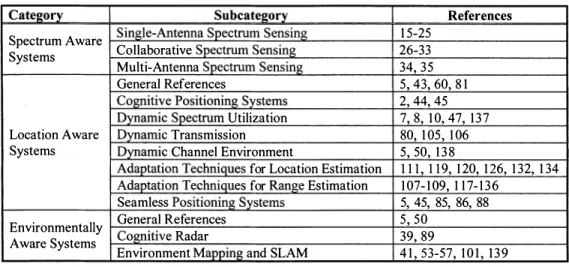
Relying on the fact that spectrum awareness (i.e., sensing, shaping, learning, and optimization) is one of the most crucial features of cognitive-radio systems, a significant portion of the studies in the literature focused on spectrum awareness and related issues [6- 1 2] . Energy detectors, autocorrelation detectors, and cyclic autocorrelation detectors are three common techniques in the literature for detection of spectrum opportunities [ 1 3 , 14]. Various approaches for spectrum sensing in cognitive-radio sys tems have been proposed in the literature. For instance, different single-antenna spectrum-sensing techniques were proposed in [ 1 5-25]. In order to further improve the performance of spectrum sensing, cooperative spectrum-sensing techniques have been developed [26-33 ] . In addition, multiple-antenna spectrum-sensing methods, such as those in [34-38] were proposed to exploit space diversity gain in spectrum-aware systems. More specifically, a spectrum-sensing technique based on an energy-detector receiver
and mUltiple antennas was proposed in [3 5]. Finally, we refer the readers to [7, 8, 1 0- 1 2] for comprehensive surveys on spectrum awareness for cognitive-radio systems.
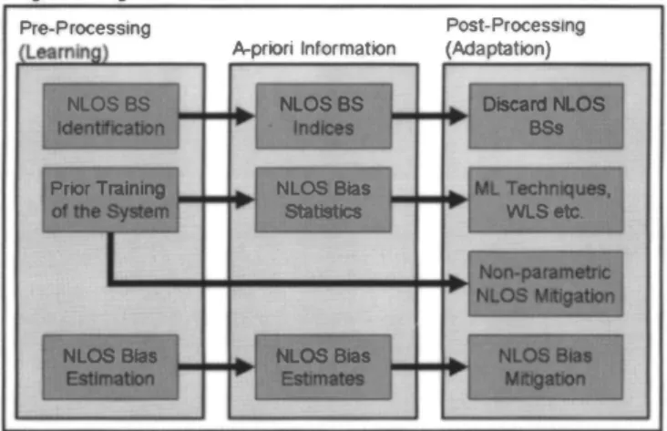
Unlike the spectrum-awareness feature, the other features of cognitive-radio systems, such as location and environmental awareness, have not been thoroughly investigated in the literature. The main milestones towards embodying location and environ mental-awareness features in cognitive-radio systems can be sum marized as follows. Haykin introduced the concept of cognitive radar, which is a way of learning about the surrounding environ ment [39, 40] . In [39], a cognitive radar model that used an intelli gent illuminator on the transmitter side and a radar-scene analyzer and Bayesian target-tracker methods on the receiver side was pro posed. This was followed by the introduction of a radio-environ ment mapping method for cognitive-radio networks [4 1 ] . A joint sequential hypothesis testing and adaptive waveform method for target recognition in cognitive radar was proposed [42] . A con ceptual framework of an environmental-awareness engine for cog nitive-radio systems, along with its main functionalities, were pro posed in [5].
On the other hand, the previous work on location awareness can be summarized as follows. A conceptual framework for the location-awareness engine of cognitive-radio systems was pro posed in [43] . Furthermore, a cognitive positioning system (CPS), which is a step towards realization of cognitive location sensing, was introduced in [2, 44] . In [2], the range-accuracy adaptation featu�e of a cognitive positioning system was introduced without providing its performance analysis. Furthermore, in [45], a high precision ranging algorithm for dynamic-spectrum-access net works was proposed. Theoretical limits on ranging for cognitive radio localization systems in the presence of interference were studied, and an optimal spectrum-allocation strategy that provides the best ranging accuracy was proposed in [46] . The fundamental limits of time-delay estimation in dispersed-spectrum cognitive radio systems were investigated in [47]. In that study, the Cramer Rao lower bounds for known and unknown carrier-frequency off set (CFO) were derived, and the effects of the number of available dispersed bands and modulation schemes were investigated. Also, [48] considered time-delay estimation in dispersed-spectrum cog nitive-radio systems, and proposed two-step approaches for utiliz ing the frequency diversity in such systems. In addition, the per formance comparison of whole and dispersed-spectrum utilization methods for cognitive-radio systems was studied in the context of time-delay estimation in [49]. Finally, the idea of seamless posi tioning as a functionality of the location-awareness engine for cog nitive-radio systems was introduced in [43 , 5] without proposing a specific technique.
In the literature, there exist studies that combine multiple dif ferent concepts for cognitive-radio systems. For instance, a con ceptual model that combines location and environmental-aware ness concepts was proposed by Yarkan et. al. [50], in order to improve the performance of cognitive-radio systems. Haykin introduced the concept of cognitive dynamic systems, in which cognitive radio for communications and cognitive radar for remote sensing were unified [5 1 ] . In addition, a unified framework that combines cognitive radio and cognitive radar was proposed in [52] . The concepts of localization and environmental mapping were merged, which is known as the simultaneous localization and map ping (SLAM) problem in the literature [53, 54] . In addition, in [55-57], an ultra-wideband- (UWB) based simultaneous localization and mapping technique for mobile nodes was proposed for simple two-wall and four-wall scenarios. In that context, a comprehensive unified cognitive-radio-system model that combined spectrum, environmental, and location awareness concepts was proposed at a
42
conceptual level in [5]. Note that [5] introduced that comprehen sive conceptual model without providing the details of how it could be implemented and designed. Therefore, in this paper, we extend the study in [5] by examining the critical implementation issues that need to be addressed for this model in order to move it from concept to reality. In addition, the challenges and efforts for the deployment of this system model are presented in this study.
The main focus of this study is to provide an in-depth discus sion and overview of challenges, efforts, limitations, and imple mentation issues for the realization of a cognitive-radio-system model with spectrum, environmental, and location-awareness capabilities. The paper is organized as follows. The overall system architecture for cognitive-radio systems with spectrum, location, and environmental-awareness capabilities is summarized in Sec tion 2. Section 3 is a brief review of spectrum-aware systems, especially spectrum sensing and utilization techniques, and spec trum regulations. In Section 4, a discussion of location-aware sys tems, along with cognitive positioning systems and seamless posi tioning systems, is presented. In Section 5, the details of environ mentally aware systems are provided by emphasizing cognitive radar and topographical information-estimation functionalities. In Section 6, the dynamic operation of cognitive-radio systems, along with challenges, adaptation techniques, and open issues, are dis cussed in the context of a cognitive-positioning system. Finally, the concluding remarks are presented in Section 7.
2.
System Model
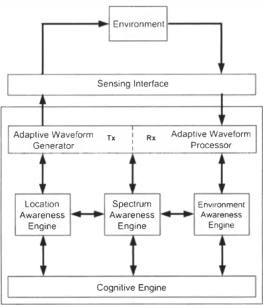
The cognitive-radio architecture [5] in Figure I is considered
to be the system model in this paper. Goal-driven and autonomous operation are two main features distinguishing cognitive radios from legacy radios. Cognitive radios achieve goals by determining
--.. Environment
I
Sensing InterraceJ
I
Adaptive Waveform Txi
Rx Adaptive WaveformI
Generator I I Processor
� j
Location Spectrum Environment
Awareness Awareness . Awareness
Engine Engine Engine
�
I
Cognitive EngineI
Figure 1. A simplified block diagram of the proposed cognitive radio-system model.
the appropriate radio parameters for the perceived, current, dynamic wireless-channel environmental conditions [58]. The goals can be network and node-level goals [59] . Since the focus of this paper is cognitive-radio nodes, node-level goals are consid ered. In addition, a goal can consist of single or multiple obj ec tives. For example, minimization of bit-error-rate (BER), maximi zation of throughput, and minimization of power consumption are three examples of cognitive-radio objectives [58]. These objectives can be achieved by using artificial-intelligence (AI) methods, such as genetic algorithms. For instance, a cognitive engine based on a multiple-objective fitness function using a simple weighted-sum method was proposed in [58] for the achievement of cognitive radio goals. That method was capable of instantly switching oper ating goals by simply modifying the objective weighting factor in dynamic wireless-channel environments.
Goal-driven and autonomous operations are managed by the cognitive engine in the system model shown in Figure 1 . In other words, the cognitive engine maps the final goals to the local goals, and assigns the local goals to the respective specialized engines. Finally, the cognitive engine collects and combines the results of the assigned local goals to achieve the final goals. Note that the cognitive-radio-system model can have many engines, such as policy, interference, and topology engines; however, in this study, we limit the system model to have three engines, which are the spectrum, location, and environmental-awareness engines. The main functionalities of the spectrum, location, and environmental awareness engines are to handle all the tasks related to the spec trum" location, and environmental information of the cognitive radio, respectively. For instance, the spectrum-awareness engine is responsible for performing spectrum-information-related tasks, such as estimation of available bands, carrier frequencies, and bandwidths. S imilarly, the environmental-awareness engine is responsible for handling environmental-information-related tasks, such as recognition of objects in the surrounding environment. Note that the environmental definition proposed in [5] is employed in this study. This is defined with the following entities: topog raphical information, object information, propagation-channel characteristics, and meteorological information. Likewise, the location-awareness engine is responsible for handling location information-related tasks, such as range and position estimation. Once the cognitive engine determines the radio parameters for achieving a final goal, it then adapts the radio parameters using the arbitrary-waveform generator/processor, as well as the sensing interface in the system model [5]. The arbitrary-waveform gen erator/processor is an interface that can generate and process any
type of waveform at the transmitter/receiver side, respectively. The sensing interface consists of different sensors, such as radio sensing, radio-vision, and radio-hearing devices, to send/acquire signals to/from the environment [5] .
Software-defined radio (SDR) i s a key enabling technology
for deploying cognitive-radio systems such as shown in Figure 1.
All the engines can be implemented in microprocessors [60] . How ever, implementing such sophisticated algorithms in microproces sors can require high power consumption, and can generate an excessive amount of heat. Therefore, low-complexity spectrum, location, and environmentally aware algorithms need to be devel oped to in order to address these two issues. In addition, small-size and low-power cooling systems can be designed. Adaptive-wave form generation and processing include performing baseband and
RF operations in the transmitter and receiver, respectively, in an
adaptive manner. Adaptive-waveform generation and processing functionalities can be deployed using reconfigurable digital-radio processors, such as FPGAs (field-programmable gate arrays) and DSPs (digital signal processors) [60] . The evaluation and compari son of reconfigurable digital-radio technologies for cognitive-radio
IEEE Antennas and Propagation Magazine, Vol. 52, No.4, August 201 0
systems was studied in [60] . One of the main challenges In imple':
menting baseband and RF functionalities is the stage of digitizing
the signal. In an ideal software-defined radio approach, the RF sig
nal is digitized right after the antenna, and then the digital RF sig
nal is processed using reconfigurable digital processors. Two main challenges to implementing such architectures are designing high performance data converters that sample the RF signal at multi gigasamples/second (Gsps) rates, and high-performance digital radio processors that run at tens of Gbps data rates. Similarly to general-purpose microprocessors, reconfigurable digital-radio processors have high-power-consumption and overheating prob lems. In the second approach, adaptive-waveform generation and processing is implemented using mixed digital and analog circuit ries. In such an approach, the signal is digitized at the IF stage, and the digital IF signal is processed by reconfigurable digital-radio processors. This relaxes the requirements of the data converters and reconfigurable digital-radio processors. On the other hand, this
approach requires the use of software-tunable RF components,
such as software-tunable filters, power amplifiers, and up/down converters. Additionally, high-performance software-tunable power circuitry, clock-generation circuitry, frequency synthesizers, and impedance-matching synthesizers are required. The further details of the requirements and challenges of implementing adap tive-waveform generation and processing can be found in [60] .
The sensing interface consists of different sensors, such as an antenna, a camera, and an acoustic sensor. The most extensively used air-sensing interface is an antenna, which is the main focus in this study. There are significant efforts towards the development
and design of software-tunable antenna systems and RF front-ends
for software-defined radios. For instance, a reconfigurable antenna was proposed in [6 1 ] that can be tuned electronically to different frequency bands while satisfying both high-efficiency and narrow instantaneous-bandwidth requirements. In addition, a novel FPGA
based RF front-end architecture was proposed in [6 1 ] . The pro
posed novel RF front-end, coupled with the reconfigurable
antenna, is a promising architecture for realizing software-defined radio.
Advanced, comprehensive, and intelligent applications can
be supported by the system model in Figure l. For instance, con
sider a scenario in which a user is employing a cognitive radio in a car, and is moving towards a harsh environment, such as a tunnel in an urban area. Assume that the cognitive-radio user operates in the normal mode before entering to the tunnel. In the normal mode, the main goal is to achieve the best throughput possible while sat isfying a power constraint. In addition, it is assumed that �a high carrier frequency is used, since penetration is not a maj or problem in the normal mode. We -call the operating mode within the tunnel the alert mode. This mode is defined as the mode in which the main goal is to keep the level of the quality of service (QoS) as close as possible to the quality-of-service level provided outside the tunnel. The location-awareness engine tracks the cognitive radio user in order to provide its position information. On the other hand, the environmental-awareness engine acquires the channel environment information within and outside the tunnel, such as the propagation model (path-loss coefficient). Furthermore, the spec trum-awareness engine provides the available bands within and outside the tunnel. The location-awareness engine detects when the cognitive-radio user enters the tunnel, and then the cognitive engine switches the operating mode from the normal to the alert mode. Since signal penetration and propagation are maj or issues for the tunnel environment, the cognitive engine lowers the carrier frequency and maximizes the transmitted power, in order to improve the penetration. In addition, it adapts the coding and modulation to combat the fading. Once the location-awareness engine detects that the cognitive-radio user has exited the tunnel,
the cognitive� engine then switches the mode back to the no-rmal mode. Note that numerous goal-driven and autonomous applica tions can be supported by the system model. Of course, such intel ligence comes with additional complexity. However, recent advances in software-defined radio technology, mobile computing, and processors, such as sophisticated FPGAs, are promising for implementing such system models in the near future [60] . There are significant efforts from academia, industry, and regulatory agencies in the development and design of cognitive-radio sys tems. For instance, a real-time MIMO OFDM (orthogonal fre quency-domain multiplex) test bed for cognitive radio networks was developed in [62], and Mishra et. al. developed a real-time cognitive-radio test bed for the physical and link layers. In addi tion, a biologically inspired cognitive-radio test bed was developed in [63, 64], in order to develop and test genetic algorithms for cog nitive-radio systems.
3.
Spectrum-Aware Systems
Dynamic spectrum utilization is an essential component of cognitive-radio and cognitive-positioning systems. As i llustrated in
Figure I, spectrum sensing is handled through the spectrum
awareness engine in a cognitive-radio system. Its output can be sent to cognitive, location, and environmental-awareness engines. A spectrum-awareness engine may also utilize the information from the other engines in order to improve its own accuracy.
As shown by numerous studies in the literature (see, e.g., [6-1 2]), the spectrum is utilized inefficiently by today's wireless net works. In many scenarios, certain parts of the spectrum are not utilized by any user, which is a waste of spectral resources. In some other scenarios, the interference from other users may be negligible, due to propagation characteristics and signal attenua tion. In such case, some secondary users can have the opportunity to re-use certain parts of the spectrum. However, such opportunis tic spectrum utilization requires reliable spectrum sensing to make sure that the frequency band of interest is not occupied by any pri mary users in a given time interval. If the spectrum is available, it may then be utilized by an opportunistic network for communica tions and/or localization purposes.
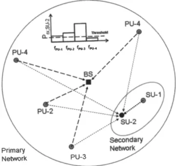
An example of an opportunistic spectrum-utilization approach is illustrated in Figure 2, where several primary users (PUs) are communicating with a base station (8S). Moreover, there is a secondary network (SN), which tries to utilize the spec tral resources of the primary network. The signals of the primary users that are far away from the secondary network are attenuated significantly, and hence their uplink (UL) spectrum may be avail able for reuse in certain regions of the secondary network. For example, SU-2 may reuse the spectrum of PU-4, since the received signal power from PU-4 is very weak at SU-2.
3.1
Spectrum Sensing
Spectrum sensing is one of the most fundamental problems for cognitive radios. Two main issues in spectrum sensing are reli ability and wideband sensing [65]. Reliable detection of the exis tence of primary users is a primary requirement for the minimiza tion of interference to existing communications. Note that a hidden node is major threat for reliable primary-user detection, where a secondary user cannot detect the primary user's signals due to shadowing. We will briefly discus two main approaches that
44
improve the reliability of spectrum sensing: collaboration, and multi-antenna-based spectrum-sensing methods.
Spectrum-sensing techniques for opportunistic spectrum access have been investigated extensively in the literature. Several single-antenna spectrum-sensing techniques were proposed in [ 1 5-25]. As discussed in [ 1 3, 1 4], there are three common techniques for detection of spectrum opportunities: energy detectors, autocor relation detectors, and cyclic autocorrelation detectors. As illus trated in Figure 2, an energy-detector receiver at SU-2 is a com mon spectrum-sensing method for determining the spectrum opportunities. An energy detector sets a threshold, and the fre quency bands with received power below the threshold are labeled as spectrum opportunities. The spectrum-sensing results may be further improved through cooperative techniques, as in [26-33], where multiple closely located receivers exchange information for more-accurately determining spectrum opportunities.
Multiple-antenna spectrum sensing [34-3 8] is a second alternative for improving the reliability of spectrum-sensing results. In Figure 3, spectrum sensing based on an energy-detector receiver and mUltiple antennas is illustrated [3 5]. After the signals arriving at different antennas are processed with a bank of square law devices and integrators, the resulting decision variables are
Primary Network
f ... 1 fP\I.J f� fPU-4
PU-3
Figure 2. An illustration of spectrum opportunities in a secon dary network that arise due to propagation effects in a pri
mary network.
P,.x;SU-2
and fpu_;denote the received signalenergy at SU-2 and the frequency band for primary user i,
resDectivelv. Antenna-1 C) '" c c .-c '" Q) c - Q) coo <t:E � :> a.� :pt) s� :::!:oo
Figure 3. Multiple-antenna spectrum sensing at a cognitive radio receiver (35).
compared with a threshold, followed by a multi-antenna spectrum sensing block. For example, in [35], binary spectrum-sensing deci sions were made corresponding to each of the antennas. The num ber of positive hypotheses (corresponding to the decision that the spectrum is occupied) were then compared with a threshold. If this was larger than the threshold, the spe�trum was occupied, and oth erwise, it was available. On the other hand, [34] coherently com bined the multiple-antenna signals, without any prior information about the primary system, and fed the spectral-correlation function of the combined signal to a feature detector for the final decision. The results in [34] and [3 5] showed considerable improvement when using multiple antennas over the single-antenna spectrum sensing technique.
Another main challenge in spectrum sensing is to sense very wide bandwidths, up to several GHz, in real time, in order to relia bly detect available bands for opportunistic usage [65). It is a
challenging task to develop and design an RF front-end and digital
signal-processing algorithms that satisfy such sensing require ments. Along this line, a multi-band joint-detection method was proposed in [65] for achieving wideband spectrum sensing.
3.2
Utilization of S pectrum Opportunities
After sensing the spectrum and determining the available fre quency bands, a cognitive-radio system needs to efficiently utilize these -spectral resources in order to perform reliable communica tions [9], localization [2, 5], and/or radar [39] functions. In utiliz ing available spectral resources, the main criteria to consider are performance, complexity, and power consumption.
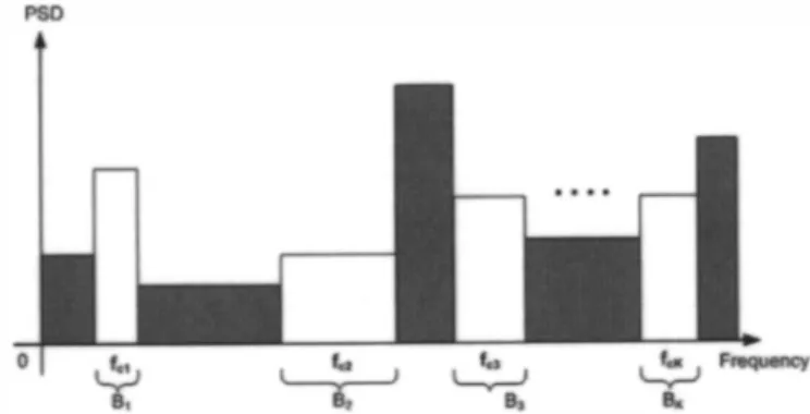
In communications systems, performance can be quantified via throughput, whereas in localization systems, it is related to average position-estimation error [66, 67). On the other hand, the performance of radar systems is characterized by probabilities of detection and false alarm, as well as accuracy of velocity and posi tion estimates (time and Doppler resolution) related to targets [68, 69). In the aforementioned systems, performance improvements can be obtained, such as an increase in system bandwidth and/or signal-to-interference-plus-noise (SINR). The main implication of improved performance with increased bandwidth is to utilize all of the available bands in the spectrum. For example, if a scenario such as in Figure 4 is considered, the best theoretical performance can be obtained when all the available bands around the center fre
quencies fc" . . . , fCK are used. However, in practical scenarios,
utilization of many dispersed bands, such as in Figure 4, can con siderably increase the complexity of the system. For example, simultaneous processing of signals that occupy various dispersed
bands may require antennas and RF components that operate on
extremely large bandwidths, which are difficult to design [67, 70). In addition to increasing complexity, the use of many dispersed frequency bands can significantly increase power consumption, which is not suitable for battery-operated applications. A suitable selection of the available bands and associated power levels should therefore be determined in order to meet performance, complexity, and cost requirements.
The center frequencies of the bands can also be important, in addition to their bandwidths, in selecting an operating spectrum from available bands. As the center frequency increases, more attenuation is expected for the signal occupying that band. Cover age of a system that employs available bands around high carrier frequencies can therefore be reduced, since signal power at a given distance decreases in such a case.
IEEE Antennas and Propagation Magazine, Vol. 52, No.4, August 201 0
"-""'"
Figure 4. An example scenario illustrating available (white) and unavailable (gray) frequency bands.
After a cognitive-radio system determines which spectrum to utilize, the next important issue is to efficiently utilize that selected spectrum. Since there is a limit on the amount of transmitted power, the allocation of the signal power among different fre quency bands, and inside different frequency components in each band, should be optimized in order to maximize system perform ance. For example, water-filling algorithms can be used to maxi mize the capacity of a communications system [7 1 , 72] . Similarly, power can be optimally distributed among available frequency components in order to improve accuracy of a ranging system [46] . Theoretical limits on range-estimation accuracy for dispersed spectrum utilization were also studied in [47]. More details on [47] are presented in Section 4.
3.3
FCC Reg ulations and Experimental
Studies
The Federal Communications Commission (FCC) in the United States has recently announced rules that allow unlicensed devices to communicate in the broadcast television (TV) spectrum, where the spectrum is not used by licensed devices [73). Even though this unused TV spectrum (commonly referred to as "white spaces") presents a significant amount of spectrum to be used by cognitive-radio devices, the FCC provides a set of conservative rules and a framework for the operation of such devices. Some rep resentative restrictions from the FCC 's Second Report and Order on the operation of white-space devices are as follows [73 ] :
"All devices, except personal/portable devices operat ing in client mode, must include a geolocation capabil ity and provisions to access over the Internet a database of protected radio services and the locations and chan nels that may be used by the unlicensed devices at each location. The unlicensed devices must first access the database to obtain a list of the permitted channels before operating."
"Fixed and personal/portable devices must also have a capability to sense TV broadcasting and wireless microphone signals as a further means to minimize potential interference. However, for TV broadcasting the database will be the controlling mechanism." "Devices must adhere to certain rules to further mitigate the potential interference and to help remedy potential interference should it occur. For example, all fixed devices must register their locations in the database. In addition, fixed devices must transmit identifying infor mation to make it easier to identify them if they are found to interfere. "
"All white space devices are subject to equipment certification by the FCC Laboratory. The Laboratory will request samples of the devices for testing to ensur� that they meet all the pertinent requirements."
"The Commission wiJI act promptly to remove any equipment found to be causing harmful interference from the market and wiJI require the responsible parties to take appropriate actions to remedy any interference that may occur."
Several cognitive-radio prototypes and related experimental work have been reported in the literature. For example, the FCC documented a comprehensive report on the performance evaluation
of prototype white-space devices in
[74].
Five devices (providedby Adaptrum, the Institute for Infocomm Research (I2R), Micro soft Corporation, Motorola Inc., and Philips Electronics North America (Philips» have been evaluated in detail for digital TV (DTV) scanning and spectrum-sensing capabilities, and field tests have been performed. In general, all the white-space devices have
been capable of perfectly detecting (with
100%
successful detection performance) clean DTV signals at input DTV powers larger
than - l l O dBm, while some of them achieved
100%
successfuldetection performance at input DTV powers lower than
-125
dBm.As such, the FCC report states that the burden of "proof of con cept" has been met. Authorized spectrum-sensing devices in com bination with geo-location and database access techniques can be used today, and devices relying on sensing alone may be addressed
in the near future
[74].
Several experimental studies specific to spectrum sensing
bave also been reported in the literature
[75-77].
For instance, in[75],
an energy-detector-based wireless test bed was developed to measure the required sensing time needed to achieve the desired probability of detection and false alarm for signals in a low-SNR region. The measurement results showed that a target probabilityof detection of
0.8 (Pd
=0.8)
with the probability of false alarmset to
5% (Pia
=5%)
could be achieved for signals greater than-104
dBm within a170
ms sensing time.4.
Location-Aware Systems
The essential requirements for goal-driven and autonomous location-aware systems are accuracy, continuity, availability, and
integrity
[5, 78].
In order for cognitive radio to support such sys-_
terns, a conceptual model for a location-awareness engine was pro
posed in
[5]
and[43].
The main functionalities of a locationawareness engine are location sensing (or a cognitive positioning system, CPS), adaptation of location-aware systems, seamless positioning and interoperability, security and privacy, statistical learning and tracking, mobility management, location-aware appli cations, and a location-awareness core. The discussion in this sec tion will focus on architectures, fundamental limits, challenges, mitigation approaches, and open issues for cognitive positioning systems and seamless positioning systems.
4.1
Cognitive Positioning Systems
A cognitive positioning system performs location-sensing functionality in a location-awareness engine. In other words, its .main task is to provide the positioning accuracy specified by the cognitive engine. In order to meet various accuracy requirements, range-accuracy adaptation can be achieved by the adaptation of
system parameters
[2].
One way to provide range-accuracy adaptation in cognitive positioning systems involves the use of Cramer-Rao lower bounds
46
(CRLBs) for the optimization of signal parameters. As an illustra tive example, consider a cognitive positioning system that per forms range calculations based on time-of-arrival (TOA) estima tion in a single-path additive white Gaussian noise (A WGN) chan nel environment. In this scenario, the Cramer-Rao lower bound on
the variance of any unbiased range estimator
J
is given by[79]
�
cVar
d
� ,{}
2J27r.JSNRf3
(1)
where
SNR
is the signal-to-noise ratio, c is the speed of light, and13
is the effective signal bandwidth, defined as132
=J:f2lsut df ,
J:ISUtdf
(2)with
SU)
denoting the Fourier transform of the transmitted signal. From Equation (I), it can be observed that the transmitter can
adapt the ranging accuracy by adjusting the SNR and/or the signal bandwidth based on feedback from the receiver. Note that the SNR can be adapted in a number of ways, such as by changing modula tion type and the number of symbols that are transmitted for time of-arrival estimation, i.e., by adjusting the ranging signal duration,
and by changing the signal power
[47].
Let's consider a numerical system design for the range-accu racy adaptation in a cognitive-radio system with the following system parameters. Assume that the cognitive-radio system has a capability to adapt the SNR by changing signal power between the
values of
Ptx,l
andPtx,2'
where�x,1
and Ptx,2 are the minimumand maximum transmitted power levels, respectively. In addition, the cognitive-radio system also has a capability to adapt effective
bandwidth between the values of 131 and
132,
where 131 and132
arethe minimum and maximum available effective bandwidths, respectively. The Cramer-Rao lower bound expression in Equa
tion
(1)
for system parametersPtx,2
=4Ptx,I
and132
=8131
isplot-ted in Figure
5.
(It is assumed thatISU)I
= I for the sake ofsimplicity.) According to the results, the cognitive radio can theo
reticalJy adapt the range accuracy between the bounds of
CRLBI
and
CRLB2•
In other words, a range-accuracy adaptation between58.88
m and0.19
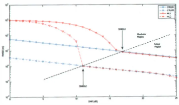
m can be achieved for the given system parame ters. Another observation is that the theoretical operational region is quantified to be 24 dB, which is simply the region between thesetwo bounds. (6 dB is due to power gain
(Ptx,zI Ptx,1
=4
), and18
dBis due to bandwidth gain
(f3i. /f3?
=64
».Note that practical systems cannot always perform very closely to the Cramer-Rao lower bounds. However, it is still rea sonable to use these bounds as a metric for adaptation, by consid ering certain margins between the bounds and the system's per formance. In addition, it is known that maximum-likelihood-(ML) and maximum-a-posteriori- (MAP) based location estimators can asymptotically achieve the Cramer-Rao lower bounds in line-of sight (LOS) and non-line-of-sight (NLOS) environments, respec
tively
[80].
Specifically, for high SNRs and/or large signal bandwidths, the positioning accuracy of a cognitive receiver can get very close to the theoretical limits. As an illustration of this issue, the performance of practical maximum-likelihood range-accuracy adaptation was evaluated for the previous system parameters, and
is compared to the theoretical bounds in Figure
5.
As can be seenfrom the figure, the performance of the practical
hood range-accuracy adaptation depended on tne SNR region [8 1 , 82).
The SNR threshold phenomenon divides the region into two sub-regions. The regions before and after the SNR threshold
(SNRth)
are called the nonlinear and linear regions, respectively. Note that practical maximum-likelihood range-accuracy adaptation asymptotically achieves the Cramer-Rao lower bound in Equation (I) in the linear region. In other words, the operational region
for practical maximum-likelihood range-accuracy adaptation is mainly determined by the SNR thresholds, which are
SNRthl
= I I dB forMLI
andSNRth2
= 1 7 dB forM�,
in this case. In addition, cognitive-radio systems can practically perform range accuracy adaptation between 8.32 m and 0. 1 9 m. Therefore, it is concluded that practical maximum-likelihood range-accuracy adaptation is desirable for operating in this linear region. (Ziv Zakai lower-bound- (ZZLB) based range-accuracy adaptation can perform very closely to practical systems in both nonlinear and lin ear regions [83, 84).) The performance of practical maximum-like lihood range-accuracy adaptation methods can be improved in terms of achieving the Cramer-Rao lower bounds asymptotically in several ways. One approach is to use the dispersed spectrum-utili zation method, which is discussed later, in Section 6. Another approach is to use practically realizable lower bounds, such as the Ziv-Zakai lower bound [83 ], as an optimization criterion for range ,accuracy adaptation methods.The expression in Equation (I) illustrates the possibility of
accuracy adaptation in cognitive positioning systems for single path additive-white-Gaussian-noise channels. However, practical cognitive positioning systems commonly operate in more-compli cated propagation environments. In addition, they have dynamic operational characteristics driven by specific goals of the system. For example, a cognitive positioning system can utilize a number of dispersed frequency bands in the spectrum (Figure 6), and can perform range estimation based on signals received from the dis persed bands. Furthermore, a cognitive-radio channel can be quite dynamic; hence, a cognitive receiver might need to employ certain adaptive-positioning algorithms. Therefore, the dynamic opera tional characteristics of cognitive systems need special attention from the viewpoint of a cognitive positioning system.
4.2
Seamless Positioning Systems
It is well known that the performance of positioning systems can be significantly affected during the transition from one type of propagation environment to another one (e.g., the transition from an outdoor to an indoor environment) [45] . Therefore, seamless positioning is an approach that enables cognitive positioning sys tems to seamlessly operate in any environment. In general, seam less positioning is defined as a system that maintains the accuracy, integrity, continuity, and availability requirements of the cognitive engine, regardless of changes in propagation environment. How ever, the performance metric of interest will be range accuracy in this discussion. Consequently, the main objective of the seamless positioning system is to maintain the range accuracy at a prede fined level in any propagation environment.
In this section, two main approaches for seamless positioning systems are discussed: Environmental-sensing-based methods, and waveform-based methods [5). The main idea behind the first approach is to jointly estimate the range parameters (e.g., the path delay in the time-of-arrival estimation scenario) and the channel parameters, such as the path-loss exponent (n) [85] and the fre
quency-dependence coefficient of the channel (I() [45] . In this
IEEE Antennas and Propagation Magazine. Vol. 52, No. 4, August 201 0
approach, the effects o f the channel environment on the range accuracy are inherently incorporated into the range estimation, since the channel parameter reflects the changes in the propagation environment. In [85], an RSS-based location-estimation method that jointly estimated the [x y] coordinate information and n was proposed. It was shown that the proposed algorithm kept the prede fined position accuracy at a constant level, regardless of different n values. Furthermore, seamless positioning systems based on the
estimation of I( for the channel propagation environment can be
developed. In this line, Qiu et. al. extended the conventional com plex channel model for wireless propagation by including the fre quency-dependent feature of the signal path, which can provide physical insights into the channel environment. The channel's transfer function, including the frequency-dependent feature of signal paths, is defined as [86]
L
H(w)
=LaleN'e-jWTlwVI ,
(3)1=1
where
L
is the number of paths, and ai, ¢JI, TI, and vI are, respectively, the distance-dependent path coefficient, phase, delay, and frequency-dependent path coefficient of the lth path. In [86], sin gular-value decomposition along with the eigen-matrix pencil
method was proposed to jointly estimate the ai, ¢JI, TI, and vI
parameters. Furthermore, according to the results reported from channel-measurement campaigns, each channel environment has
different I( values. For example, the channel parameters for the
IEEE 802. 1 5 .4a channel measurements are tabulated in Table I
[87] . In these results, it was assumed that all the paths had the
same frequency-dependent distortion, i.e., vI = -21(. This implies
that K is one of the characteristic parameters for a channel
environment. Hence, seamless positioning systems based on I(
estimation can be developed.
PSO
Figure 6. An illustration of dispersed spectrum utilization in cognitive-radio systems.
Table 1. The measured I( values of some ultra-wideband
(UWB) channels 187).
Channel Models I(
CM 1 Residential Indoor LOS 1 . 1 2
CM2 Residential Indoor NLOS 1 .5 3
CM3 Office Indoor LOS 0.03
CM4 Office Indoor NLOS 0.7 1
CM5 Outdoor LOS 0. 1 2
CM6 Outdoor NLOS 0. 1 3
CM7 Industrial LOS -1 . 1 03
CM8 Industrial NLOS - 1 .427
Since estimation of a single channel parameter may not give sufficient information regarding the channel's environment, multi ple parameters related to the channel's environment can be esti mated for seamless positioning. This requires development of rapid and low-complexity signal-processing techniques.
The second approach for seamless positioning is the wave form-based method. This method selects the most-appropriate waveforms for given accuracy requirements and environment types
[88].
This requires a cognitive-radio system equipped with multi ple waveforms, such as global positioning system (OPS), Oalileo,30,
ultra-wideband (UWB), wireless local-area-network (WLAN),and Bluetooth systems. The readers are referred to
[88]
for furtherdetails.
5.
Environmentally Awate Systems
Environmental awareness is one of the most crucial functionalities of a cognitive-radio system, since the channel's environment is the bottleneck of wireless-communications sys tems. In order for cognitive-radio systems to interact and learn the surrounding environment, a conceptual model for an environ
mental-awareness engine (c.f. Figure 1 ) was proposed in
[5].
Inessence, the subsystem of the model corresponded to the main entities of an environment, which are topographical information, object recognition and tracking, propagation-channel characteris tics, meteorological information, environmental sensing, environ mentally aware applications, and an environmental-awareness engine core. The environmental-awareness engine core (which acts
like the radio-environment "mapper" in
[41])
collects all the environmental information from each aforementioned subsystem to form the complete radio-environment map at a given time.
In this section, the implementation options and challenges for environmental sensing and mapping using cognitive-radar func tionalities of the environmental-awareness engine are discussed.
5.1
Cognitive Radar
In environmentally aware systems, cognitive radars can be used to provide information related to the objects in an environ ment, which can be considered to be an environmental sensing method. The main task of a cognitive radar is to provide object detection, identification, and tracking capabilities - based on intel ligent signal-processing techniques - and feedback from the
receiver to the transmitter
[39, 89].
Unlike conventional radars, acognitive radar "learns" its environment, and preserves the infor mation content of radar returns by applying Bayesian approaches
[7
9]
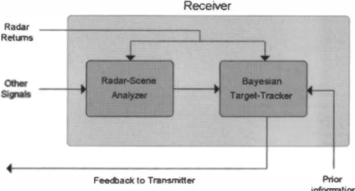
.A generic block diagram of a cognitive radar is illustrated in Figure 7. The transmitter illuminates the environment by sending a specific signal to the environment, and the signal reflections, called radar returns, are collected by the receiver. The radar returns con tain information related to the environment, i.e., to the objects in the environment. In addition to the radar returns, the receiver can collect information-bearing signals that are present in the environ ment, such as temperature and rain intensity (i.e., meteorological
information)
[39].
By having current and forecasted meteorologicalinformation, such as rain intensity and temperature, a cognitive
radio can accordingly adapt itself
[5].
For instance, rain can havesignificant effects on the performance of broadband fixed
wireless-48
Figure 7. A block diagram of a cognitive-radar system.
Radar R et� .� Receiver
J.
J.
RacIIroScene BayeIiIIn "..,.. T.,.T,.. Feedback to Transmitter ...-Prior informationFigure 8. A block diagram of a cognitive-radar receiver.
access links (e.g., fixed WiMAX)
[90],
especially operating athigher carrier frequencies. One of the performance parameters that can be affected by rain is the carrier-to-interference ratio (C/I), and this performance metric depends on the rain intensity along the location of the desired signal path and the interferer signal paths. Some of the representative scenarios showing the rain effects on C/I performance of broadband fixed wireless-access links are given
as follows
[90]:
rain-induced CII degradation, rain-induced C/Iimprovement, and no C/I change. The details of these scenarios
can be found in
[90].
If a cognitive radio or network has a capability to acquire the rain intensity of local regions from a central meteorological server or the Internet, then C/I adaptation can
accordingly be performed
[5].
Furthermore, according to an NSFsponsored study performed by the University of North Texas
[91],
the temperature and humidity affect the received signal strength (RSS). It was observed that higher temperature can lead to a slight
decrease in received signal strength, and there is a
2
to5
dBmreceived signal strength loss as the temperature goes from
25°C
to45°C.
In addition, as humidity increases, the received signal strength becomes stronger. As a result, the cognitive radio can adapt the link according to the temperature and humidity in the operating environment. Note that he main task of the receiver is to use all the incoming signals and the prior information about the environment in order to perform target detection, identification, and tracking.An important property of a cognitive-radar system is the presence of feedback from the receiver to the transmitter. Based on the feedback from the receiver, the transmitter can be adapted for improved performance. In other words, intelligent sig
nal processing is facilitated by the presence of feedback
[39].
Notethat the feedback can be easily provided for monostatic radars, i.e., when the transmitter and the receiver are co-located. However, for bistatic radars, the design of feedback mechanisms can be chal lenging.
The main blocks of a cognitive-radar receiver are the radar scene analyzer and the Bayesian target tracker, as shown in Fig
ure
8.
The radar-scene analyzer is the unit that extracts information�r---�---.---.---r---����� ... ... , . .., �t_< ... _=___:.-... ...�... _ � " -, -- -- ---- --
:
- - --;;
-��.---_+---�.�---!---i • .---iFigure 5. Operational regimes for range-accuracy adaptation .
. . - '-"- . . -, ,- -" " / I / ;" \ , '" / . . . ' . . . . ... . Mirror Imege • • •• � ... oI WeU l • -" W81 1 , I / / , '" / ,-/ '.-" --" '-" . . . ... . , ."'" . ... _ . . _ . . -••• ••• •• • •• ••• i
Figure 9. Two-dimensional indoor mapping without any infra
structure (modified from (54]).
about the environment based on radar returns and other signals obtained from the environment [39] . The Bayesian-target-tracker unit uses the radar returns, the available prior information, and the statistical information provided by the radar-scene analyzer in order to employ Bayesian strategies [79, 92] for object detection and tracking. (The information provided to the Bayesian target tracker by the radar-scene analyzer is commonly in the form of parameters characterizing certain statistical distributions related to various radar returns [39] .) In other words, the Bayesian-target tracker unit updates the prior information about the objects in the environment, based on information provided by the radar-scene analyzer and the observed radar returns. Hence, it basically calcu lates posterior distributions of certain events (e.g., an object to be present at a certain position at a given time) in the environment, based on all the available information.
5.2
Environmental Mapping and
Topographical Information Estimation
UWB technology is capable of providing high-data-rate and robust communications and high-precision positioning, due its numerous attractive features. In addition to the aforementioned applications, UWB technology is traditionally used for radar appli cations [93 ] . Furthermore, UWB technology has been considered an integral part of new emerging technologies, such as cognitive radio systems [52, 60, 94-99]. In other words, the connection between UWB and cognitive-radio systems is in the interest of many studies in the literature, and UWB is considered a part of cognitive-radio systems in those studies. For instance, UWB was considered as a solution for underlay spectrum access [96], control channel [95], and active interference cancellation [97] issues in cognitive-radio systems. In addition, numerous UWB-based cog nitive-radio test beds, such as [3 1 , 52, 99] have been developed for demonstrating different applications. As a result, UWB can be considered to be another waveform type in the waveform library of cognitive-radio systems. Apart from the above applications of UWB positioning and communications in cognitive-radio systems, the UWB radar concept can be applied to cognitive-radio systems towards the realization of environmental awareness, which is con sidered in this study.
It is not an easy task to acquire complete knowledge about the surrounding environment using a single method or technology since the environment consists of different entities: topographical information, object recognition and tracking, channel-propagation characteristics, and meteorological information. Therefore, it is a more-efficient approach to use different methods and technologies to acquire the information about each entity of the environment. For instance, UWB radar technology can be used to detect, iden tify, and track the objects in an environment. Note that UWB can provide such capabilities for short ranges, and extending the range of UWB technology is an open research topic. On the other hand, the topographical information of an environment can be acquired by cognitive radio using digital elevation models (DEMs) and geo graphical-information-system (GIS) databases. The details of this approach can be found in [49].
One of the important characteristics of a cognitive-radio sys tem is that it can learn/map its physical surroundings and topogra phy [5, 4 1 ], even in the absence of any infrastructure. A cognitive radio device can achieve this through listening to the returns of its own transmitted signals, as well as the signals transmitted by other cognitive-radio devices. Having an accurate map of the environ ment may have multiple uses. It can be used for situa tion/environment awareness purposes, where, for example, a
fire-50
fighter can be guided to find his or her way out of a burning building. In fact, the European-Union-funded project EUROPCOM [ 1 00, 1 0 1 ] envisions a scenario where UWB radio is used in emer gency situations (particularly within large buildings) where the locations of the personnel are monitored in a control vehicle. Since the building map may not be available a priori, or it may change
due to damaged walls, etc., RF signals can be used to obtain an up
to-date map of the building.
Having an accurate map of the environment also improves the position-estimation accuracy of the cognitive-radio device. This issue is commonly referred as the simultaneous localization and mapping (SLAM) problem in the literature (particularly, in the robotics-research community), where a mobile node jointly and incrementally builds a map of the environment while simultane ously estimating its own location [53, 54]. In [53], it was proven that the simultaneous localization and mapping problem can be solved in such a way that the mapping uncertainty and the position uncertainty can be improved up to a fundamental limit determined by the initial position uncertainty. If the sensor measurements for a
cognitive-radio device i at time
t
are given by range measurementsdj
and angle measurementsIf/j '
a vectorvt =
{d]
, If/],d2,1f/2,
..., dM , If/M }
can be defined forM
features of the environment. The joint state space of the cognitive device and the environment is then given by [53](4)
where the tuple
(x, y, n)
defines the pose of the cognitive-radiodevice, and
(Xj , yd
is the position of the ith feature of the environment. The simultaneous localization and mapping problem is then defined as the estimation of following posterior distribution [54]
(5)
where
ut
=(!J.dt , !J.(}t )
is the relative transitional and rotational displacement of the cognitive radio device at time
t.
In [55-57], UWB transceivers were used for simultaneous localization and mapping of a mobile node in simple two-wall and four-wall scenarios. The advantage of UWB for simultaneous localization and mapping is that due to their large bandwidths, UWB signals can resolve individual returns from different reflec tions with high timing accuracy. Therefore, the information embedded within distinct multipath components can be extracted, which is not possible with narrowband radios. Moreover, since a small number of dominant echoes corresponds to large flat sur faces such as walls, these dominant components can be captured by an appropriate thresholding method [55]. (Several other less significant multipath components are typically scattered from smaller objects.)
Figure 9 illustrates a simple scenario in which two cognitive radio nodes (CNs) can receive line-of-sight or reflected signals from each other (or reflections of their own signals) [55]. By proc essing different echoes, the mobiles can obtain the distances to each other as well as to the walls. In this scenario, CN- l receives three replicas of its own transmitted signal after reflections from the walls: one from wall- I , another from wall-2, and a third one from around the intersection of wall- l and wall-2, which is a dou ble reflection (not shown in Figure 9). While CN- I cannot distin
guish these, it can obtain three distance measurements,
d],j '
j E
{
1, 2, 3}
. Similarly, CN-2 receives three different echoes of itsown transmitted signal to obtain distance measurements
d2,J'
j
E{
1, 2, 3}
. Note that corresponding to each distance measurement, a position circle can be drawn around a CN, and the tangents to this circle are possible locations of a wall. If the distance between CN- I and CN-2 is known, the common tangents to the two position circles for CN- I and CN-2 yield possible locations for
a wall. For example, for measurements
d\,2
andd2,2'
there are twocommon tangents: one corresponds to wall-2, and the second one is the mirror image of wall-2 with respect to the line passing from CN- l and CN-2. Since there are three measurements for each CN,
this corresponds to 3 x 3 x 2 = 1 8 total hypotheses for the two walls,
including the mirror images [54] . The ambiguity can be resolved by checking if any two wall combinations predict the double reflections with appropriate delays, and can yield the channel impulse response (CIR) from the other CN. As apparent from the above discussion, the key parameter for finding the locations of the walls is the distance between two CNs. This parameter can be estimated by utilizing the channel impulse response between the two CNs, which has four echoes: the line-of-sight signal, two sin gle reflections, and one double reflection. For further details and a discussion for a four-wall scenario, the reader is referred to [55].
6.
Dynamic Operation of
Cognitive-Radio Systems
In this section, the dynamic nature of cognitive-radio systems is discussed in the context of cognitive positioning systems. More specifically, the issues related to the dynamic nature of cognitive positioning systems are considered, and performance limits, chal lenges, mitigation algorithms, and adaptation techniques are dis cussed.
6.1
Dynamic S pectrum Utilization
Cognitive-radio systems facilitate opportunistic use of spec tral resources. In other words, a cognitive-radio system can employ signals with dispersed frequency spectra, as shown in Figure 6. Therefore, the ranging accuracy of cognitive positioning systems depends also on the number of available frequency bands, and the bandwidth and center frequency of each of these bands.
In order to investigate the performance of cognitive position ing systems in dynamic spectrum-access scenarios, consider a cog
nitive-radio system that allocates K different frequency bands, as in
Figure 6 [47] . Assume a cognitive positioning receiver with K dif
ferent branches, each of which processes one of the K frequency
bands: i.e., each branch filters, amplifies, and down-converts the signal according to one of the center frequencies. (Another way to utilize dispersed spectra in cognitive positioning systems is to con sider the received signal as an orthogonal frequency-division mul
tiplexing (OF OM) signal, with zero coefficients at the sub-carriers
corresponding to the unavailable bands [ 1 02- 1 04]. Such an approach can require processing of very large bandwidths when the available spectrum is quite dispersed [47].). Then, the baseband representation of the received signal in the ith branch can be expressed as
(6)
for i = I, . . . , K , where s;
(t)
is the baseband representation of theIEEE Antennas and Propagation Magazine, Vol. 52, No. 4, August 201 0
transmitted signal corresponding to the ith band, a; =
a;eJlPi
andOJ; respectively represent the channel coefficient and the carrier
frequency offset (CFO) for the signal in the ith branch, r is the
time of arrival, and n;
(t)
is complex Gaussian noise withindependent and white components, each having spectral density
2
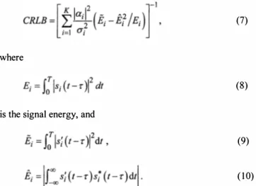
(Y; .In [47], the Cramer-Rao lower bounds were derived for the signal model in Equation (6) for the cases of known and unknown carrier-frequency offsets. As an example, for known carrier-fre quency offsets, the lower limit on the variance of unbiased time delay estimators was expressed as follows:
(7)
where
(8) is the signal energy, and
(9)
( 1 0) In other words, the Cramer-Rao lower bound depends on the SNRs of the available frequency bands, as well as on the properties of the ranging signal. In fact, it can be shown that for linearly modulated ranging signals with constant envelopes, the effects of unknown carrier-frequency offsets and channel coefficients can be mitigated for certain pulse shapes [47] . Therefore, range accuracy can be adapted in cognitive positioning systems by selecting the modula tion type in addition to adjusting the number of ranging symbols, SNR levels, and/or the number of dispersed bands in the spectrum.
As an example, the Cramer-Rao lower bound in Equation (7) was plotted in Figure 1 0 as a function of the number of dispersed bands, where each band was assumed to have the same SNR and bandwidth [47]. Specifically, the received signal in each branch was modeled as a 1 6-PSK modulated sequence of 1 6 symbols. (For
10� .-����r-����r.�.7.7. .
.
� . . �.r.� . . �======�� -SNR-sd8 -&- SNR-1OdB -....- SNR_l 5dB .. . ..
...��
.
.. ...�
.--
�
�
�
��
--
�
' .
-
.
�
.
�
..�
. .�
. .�
.
�
.
�
. .�
. .1
. :.: .. : .. ' : .
r-
::
. .?
:
::
:7
::
:
�
:
. .: ..
�
. ..��
�-l
.....
. .
... ..
.
. ..
....
...
..
.. .... .. .. ... ..
. .. . ..
...
. . . ....
. ..
.. .
. . . :' .. ...
. ..
..
..
... . : .... .... .
.
. , - , -.
.. " . ... .. . . . . . • . • • . • • • .. • . . . ! . . . • . . • . . ;. • • • • • • • • • • • 0 • • 10� L---�---�---7---� 1 2 3 . 5 KFigure 10 .