ELECTROSPINNING OF CYCLODEXTRIN
FUNCTIONALIZED NANOFIBERS AND THEIR
APPLICATIONS
A DISSERTATION SUBMITTED TO
THE GRADUATE SCHOOL OF ENGINEERING AND SCIENCE
OF BILKENT UNIVERSITY
IN PARTIAL FULFILLMENT OF THE REQUIREMENTS FOR
THE DEGREE OF
DOCTOR OF PHILOSOPHY
IN
MATERIALS SCIENCE AND NANOTECHNOLOGY
By Zeynep Aytaç
ii
ELECTROSPINNING OF CYCLODEXTRIN FUNCTIONALIZED NANOFIBERS AND THEIR APPLICATIONS
By Zeynep Aytaç August 2016
We certify that we have read this dissertation and that in our opinion it is fully adequate, in scope and in quality, as a dissertation for the degree of Doctor of Philosophy.
Tamer Uyar (Advisor)
Hilal Türkoğlu Şaşmazel
Engin Durgun
Gülüm Şumnu
Urartu Özgür Şafak Şeker
Approved for the Graduate School of Engineering and Science
Levent Onural
iii
ABSTRACT
ELECTROSPINNING OF CYCLODEXTRIN FUNCTIONALIZED
NANOFIBERS AND THEIR APPLICATIONS
Zeynep Aytaç
Ph.D. in Materials Science and Nanotechnology Advisor: Tamer Uyar
August, 2016
Electrospinning is a widely used versatile method to produce nanofibers with high surface to volume ratio and porous structure. Owing to the unique properties, electrospun nanofibers are of great importance as a carrier matrix for
drugs; antioxidant, and antibacterial agents, flavour/fragrances. Though
polymers are material of choice for producing electrospun nanofibers, it is likely to obtain nanofibers from low molecular weight molecules. Cyclodextrin (CDs) are intriguing molecules having the capability of forming inclusion complex (IC) with numerous guest molecules such as drugs, food additives, flavour/fragrances, antioxidant and antibacterial agents. Therefore, CD-ICs enhance solubility, reduce volatility, and provide controlled release of the guest molecules. Integrating CD-ICs with electrospinning opens a new door to produce remarkable materials.
In this thesis, nanofibers containing CD-ICs of bioactive agents including antioxidant/antibacterial and flavour/fragrance molecules were produced via electrospinning technique. Firstly, CD-ICs of antioxidant/antibacterial compounds (gallic acid, α-tocopherol, quercetin, and thymol) were synthesized and then, added into polylactic acid or zein solutions to produce CD-IC incorporated electrospun polymeric nanofibers. Afterwards, the release behavior, antioxidant and antibacterial activity of these nanofibers were
iv
investigated. In addition, the potential use of these nanofibers as active food packaging and delivery material was revealed by packing meat samples by these nanofibers. Secondly, electrospun nanofibers were developed as a releasing material from CD-ICs of volatile flavour/fragrance molecules (geraniol, limonene, and linalool) without using polymeric matrix. The preservation of volatile compounds is shown to be possible to a great extent with antibacterial CD-IC nanofibers. Furthermore, the shelf life of flavour/fragrance molecules has been enhanced at least 50 days by CD-IC nanofibers. Finally, for the first time in the literature core-shell nanofibers were designed by using CD-IC of curcumin, an antioxidant molecule and polylactic acid solutions as core and shell, respectively. The ability of core-shell nanofibers as a drug delivery carrier was suggested by release and antioxidant activity tests. To conclude, CD-IC incorporated electrospun nanofibers produced by three different approach is shown to be used as efficient material for various applications particularly for food packaging and drug delivery.
Keywords: electrospinning, nanofiber, polylactic acid, zein, core-shell nanofibers, cyclodextrin, inclusion complex, antioxidant, antibacterial, flavour/fragrance, food packaging, drug delivery.
v
ÖZET
ELEKTROEĞİRME YÖNTEMİ İLE ÜRETİLEN
SİKLODEKSTRİN FONKSİYONLU NANOLİFLER VE
UYGULAMA ALANLARI
Zeynep Aytaç
Malzeme Bilimi ve Nanoteknoloji Programı, Doktora Tez Danışmanı: Tamer Uyar
Ağustos, 2016
Elektroeğirme, yüksek yüzey alanına ve gözenekli yapıya sahip nanoliflerin üretimi için sıklıkla kullanılan verimli bir metottur. Bu teknik ile üretilen nanolifler eşsiz özellikleri nedeniyle ilaç; antioksidan ve antibakteriyel maddeler, tat/koku maddeleri için taşıyıcı matriks olarak büyük önem taşımaktadırlar. Bu metotla nanolif üretmek için genellikle polimerler kullanılsa da, polimerik olmayan moleküllerden de nanolifler üretilebilmektedir. Siklodekstrinler (CD’ler) ilaç, gıda katkı maddeleri, tat/koku maddeleri, antioksidan ve antibakteriyel maddeler gibi pek çok molekül ile inklüzyon kompleksi (IC) yapabilme özelliğine sahiptir. Dolayısıyla, CD-IC’ler bu moleküllerin çözünürlüklerinin arttırılması, uçuculuklarının azaltılması ve kontrollü salımlarının sağlanması için kullanılmaktadır. CD-IC’lerin
elektroeğirme tekniği ile birleştirilmesi dikkat çekici malzemelerin
üretilmesinde yeni bir yol açmıştır.
Bu tez çalışması kapsamında, antioksidan/antibakteriyel ve tat/koku maddeler gibi bioaktif maddelerin CD-IC’lerini içeren nanolifler elektroeğirme tekniği ile üretilmiştir. İlk olarak, antioksidan/antibakteriyel moleküllerin (gallik asit, α-tokoferol, kuersetin, timol) CD’ler ile IC’leri sentezlenmiştir. Daha sonra bu CD-IC’ler polilaktik asit ve zein solüsyonlarına eklenerek CD-IC’leri içeren
vi
polimerik nanolifler elektroeğirme yöntemi ile elde edilmiştir. Bu nanoliflerin salım davranışları, antioksidan ve antibakteriyel aktiviteleri de araştırılmıştır. Buna ek olarak, üretilen nanoliflerin aktif gıda paketleme ve ilaç salım malzemesi olarak kullanım potansiyeli, nanolifleri et örneklerine sararak yapılan testlerle gösterilmiştir. Bir sonraki aşamada; geraniyol, limonen, linalool gibi uçucu olan tat/koku moleküllerinin CD-IC’lerinden polimer kullanılmadan elektroeğirme metodu ile nanolifler geliştirilmiştir. Oldukça uçucu bir yapıya sahip olan bu moleküllerin, korunmaları CD-IC nanolifleri ile büyük oranda sağlanmıştır. Ayrıca, tat/koku moleküllerinin raf ömrü en azından 50 güne kadar geliştirilmiştir. Daha sonraki çalışmamızda, antioksidan bir molekülün (kurkumin) CD-IC solüsyonu ve polilaktik asit solüsyonlarının sırasıyla çekirdek ve kabuk olarak kullanıldığı çekirdek-kabuk nanolifleri de elektroeğirme tekniği yardımıyla ilk defa elde edilmiştir. Bu nanoliflerin ilaç taşıyıcı sistemlerdeki potansiyeli salım ve antioksidan aktivite testleri ile gösterilmiştir. Sonuç olarak, CD-IC’lerin katıldığı ve elektroeğirme metodu kullanılarak üç farklı yaklaşımla üretilen nanoliflerin gıda paketlemesi ve ilaç salım sistemleri başta olmak üzere pek çok alanda uygulanabilecek etkili malzemeler oldukları gösterilmiştir.
Anahtar kelimeler: elektroeğirme, nanolif, polilaktik asit, zein, öz-kabuk nanolifleri, siklodekstrin, inklüzyon kompleks, antioksidan, antibakteriyel, esans, tat/koku maddeleri, gıda paketlemesi, ilaç salımı.
vii
ACKNOWLEDGEMENTS
Firstly, I would like to express my deepest gratitude to my supervisor Prof. Tamer Uyar for his knowledge, invaluable guidance, encouragement and support during the course of this research. I would like to thank Prof. Turgay Tekinay and Prof. Engin Durgun for their guidance during my PhD studies, as well as to my jury members Prof. Gülüm Şumnu, Prof. Hilal Türkoğlu Şaşmazel, and Prof. Urartu Özgür Şafak Şeker for their contribution to my thesis.
I would like to give special thanks to Dr. Nalan Oya San Keskin and Dr. Semran İpek Küskü for their fruitful collaboration.
I would like to acknowledge to former and present members of Uyar Research Group Dr. Amaresh Chandra Pradhan, Dr. Ali Demirci, Dr. Anitha Senthamizhan, Dr. Aslı Çelebioğlu, Dr. Brabu Balusamy, Dr. Fatma Kayacı-Şenırmak, Dr. Kugalur Shanmugam Ranjith, Dr. Osman Arslan, Ömer Faruk Sarıoğlu, Dr. Serkan Demirci, Dr. Sesha Vempati, Şefika Eroğlu Özcan, Yelda Ertaş, Zehra İrem Yıldız.
I am also thankful to Fatih Büker, Dr. Gökçe Çelik, Mustafa Doğan, Mustafa Güler, and Zeynep Erdoğan for their technical assistance. I would also like to thank old and present UNAM members Gonca Ünal, Murat Biçici, Suna Temiz and Bilkent University member Nimet Kaya.
I owe special thanks to my friends, Dr. Gözde Uzunallı, Dr. Aslı Çelebioğlu and Özlem Bıkmaz. Thank you for encouragement and support through these years.
viii
I would like to express my dearest gratitude to my mother, father and sister for their love, support and understanding.
I would like to thank The Scientific and Technological Research Council of Turkey (TUBITAK, project #111M459 and #213M185) for funding my research and BİDEB 2211-C for PhD scholarship.
ix
To My grandmothers,
x
CONTENTS
ABSTRACT ... iii ÖZET ... v ACKNOWLEDGEMENTS ... vii CONTENTS ... xLIST OF FIGURES ... xvi
LIST OF TABLES ... xxii
LIST OF ABBREVIATIONS ... xxiii
Chapter 1 ... 1
INTRODUCTION ... 1
1.1 Electrospinning ... 2
1. 2 Cyclodextrins ... 7
1.3 Electrospun nanofibrous webs as carrier for bioactive compounds ... 11
Chapter 2 ... 17
ENCAPSULATION OF CYCLODEXTRIN INCLUSION COMPLEXES IN ELECTROSPUN POLYMERIC NANOFIBERS ... 17
2. Encapsulation of gallic acid/cyclodextrin inclusion complex in electrospun polylactic acid nanofibers: Release behavior and antioxidant activity of gallic acid ... 18
2.1 Introduction ... 18
2.2 Experimental ... 21
2.2.1 Materials ... 21
2.2.2 Preparation of inclusion complex and physical mixture ... 21
2.2.3 Preparation of electrospinning solutions ... 22
2.2.4 Electrospinning ... 22
2.2.5 Characterizations and measurements ... 23
2.2.6 Computational method ... 26
2.3 Results and discussion ... 27
2.3.1 Phase solubility studies ... 27
2.3.2 Structural characterization of inclusion complex ... 28
2.3.3 Thermal analysis of inclusion complex ... 29
xi
2.3.5 Molecular modeling of inclusion complex ... 33
2.3.6 Morphology analysis of nanofibers ... 35
2.3.7 In vitro release study ... 38
2.3.8 Antioxidant activity ... 41
2.4 Conclusion ... 42
3. Developing antioxidant food packaging using α-tocopherol/γ-cyclodextrin-inclusion complex incorporated polylactic acid nanofibers produced via electrospinning ... 44
3.1 Introduction ... 44
3.2 Experimental ... 46
3.2.1 Materials ... 46
3.2.2 Preparation of inclusion complex ... 47
3.2.3 Preparation of electrospinning solutions ... 47
3.2.4 Electrospinning ... 48
3.2.5 Characterizations and measurements ... 48
3.3 Results and discussion ... 51
3.3.1 Structural characterization of inclusion complex ... 51
3.3.2 Thermal analysis of inclusion complex ... 52
3.3.3 The molar ratio of inclusion complex ... 53
3.3.4 Morphology analysis of nanofibers ... 54
3.3.5 In vitro release study ... 55
3.3.6 Antioxidant activity ... 56
3.3.7 Lipid oxidation analysis (TBARS) ... 57
3.4 Conclusion ... 59
4. Antioxidant electrospun zein nanofibers incorporating quercetin/γ-cyclodextrin-inclusion complex ... 61
4.1 Introduction ... 61
4.2 Experimental ... 63
4.2.1 Materials ... 63
4.2.2 Preparation of inclusion complex ... 63
4.2.3 Preparation of electrospinning solutions ... 63
4.2.4 Electrospinning ... 64
xii
4.3 Results and discussion ... 66
4.3.1 Structural characterization of inclusion complex ... 66
4.3.2 Thermal analysis of inclusion complex ... 67
4.3.3 The molar ratio of inclusion complex ... 68
4.3.4 Morphology analysis of nanofibers ... 69
4.3.5 Antioxidant activity ... 70
4.4 Conclusion ... 71
5. Antibacterial packaging material designed by encapsulation of thymol/cyclodextrin-inclusion complex in electrospun zein nanofibers ... 72
5.1 Introduction ... 72
5.2 Experimental ... 74
5.2.1 Materials ... 74
5.2.2 Preparation of inclusion complex ... 74
5.2.3 Preparation of electrospinning solutions ... 74
5.2.4 Electrospinning ... 75
5.2.5 Characterizations and measurements ... 76
5.3 Results and discussion ... 79
5.3.1 Structural characterization of inclusion complex ... 79
5.3.2 Thermal analysis of inclusion complex ... 80
5.3.3 The molar ratio of inclusion complex ... 81
5.3.4 Morphology analysis of nanofibers ... 82
5.3.5 Release study ... 83
5.3.6 Antibacterial activity ... 85
5.4 Conclusion ... 88
Chapter 3 ... 89
ELECTROSPINNING OF POLYMER-FREE CYCLODEXTRIN INCLUSION COMPLEX NANOFIBERS ... 89
6. Electrospinning of polymer-free cyclodextrin/geraniol-inclusion complex nanofibers: enhanced shelf-life of geraniol with antibacterial and antioxidant properties ... 90
6.1 Introduction ... 90
6.2 Experimental ... 93
xiii
6.2.2 Preparation of electrospinning solutions ... 94
6.2.3 Electrospinning ... 94
6.2.4 Characterizations and measurements ... 95
6.3 Results and discussion ... 100
6.3.1 Phase solubility studies ... 100
6.3.2 Morphology analysis of nanofibers ... 102
6.3.3 The molar ratio of inclusion complex ... 105
6.3.4 Thermal analysis of nanofibers ... 107
6.3.5 Structural characterization of nanofibers ... 111
6.3.6 Release study ... 113
6.3.7 Antibacterial activity ... 118
6.3.8 Antioxidant activity ... 120
6.4 Conclusion ... 123
7. Fast-dissolving, prolonged release and antibacterial cyclodextrin/limonene-inclusion complex nanofibrous webs via polymer-free electrospinning ... 125
7.1 Introduction ... 125
7.2 Experimental ... 127
7.2.1 Materials ... 127
7.2.2 Preparation of electrospinning solutions ... 127
7.2.3 Electrospinning ... 128
7.2.4 Characterizations and measurements ... 128
7.2.5 Computational method ... 132
7.3 Results and discussion ... 133
7.3.1 Phase solubility studies ... 133
7.3.2 Molecular modeling of inclusion complex ... 134
7.3.3 Morphology analysis of nanofibers ... 137
7.3.4 The molar ratio of inclusion complex ... 140
7.3.5 Thermal analysis of nanofibers ... 143
7.3.6 Structural characterization of nanofibers ... 148
7.3.7 Release study ... 149
7.3.8 Antibacterial activity ... 152
xiv
8. Fast-dissolving delivery membranes produced from electrospun polymer-free cyclodextrin/linalool-inclusion complex nanofibers with prolonged release and
antibacterial activity ... 155
8.1 Introduction ... 155
8.2 Experimental ... 157
8.2.1 Materials ... 157
8.2.2 Preparation of electrospinning solutions ... 157
8.2.3 Electrospinning ... 158
8.2.4 Characterizations and measurements ... 158
8.3 Results and discussion ... 161
8.3.1 Morphology analysis of nanofibers ... 161
8.3.2 The molar ratio of inclusion complex ... 164
8.3.3 Thermal analysis of nanofibers ... 167
8.3.4 Structural characterization of nanofibers ... 171
8.3.5 Release study ... 171
8.3.6 Antibacterial activity ... 175
8.4 Conclusion ... 176
Chapter 4 ... 177
ELECTROSPINNING OF CORE-SHELL NANOFIBERS FROM CYCLODEXTRIN INCLUSION COMPLEXES ... 177
9. Core-shell nanofibers via electrospinning for drug delivery application ... 178
9.1 Introduction ... 178
9.2 Experimental ... 180
9.2.1 Materials ... 180
9.2.2 Preparation of electrospinning solutions ... 180
9.2.3 Electrospinning ... 181
9.2.4 Characterizations and measurements ... 182
9.3 Results and discussion ... 184
9.3.1 Morphology analysis of nanofibers ... 184
9.3.2 Structural characterization of nanofibers ... 185
9.3.3 Thermal analysis of nanofibers ... 186
9.3.4 Antioxidant activity ... 188
xv
9.3.6 In vitro degradation test ... 190
9.4 Conclusion ... 191
Chapter 5 ... 193
CONCLUSION AND FUTURE PERSPECTIVES... 193
LIST OF PUBLICATIONS ... 198
xvi
LIST OF FIGURES
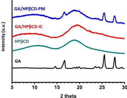
Figure 1. Schematic view of the electrospinning set-up. ... 3 Figure 2. Electrospinning set-up at UNAM. ... 3 Figure 3. The photograph of core-shell nozzle and schematic representation of electrospinning of core-shell nanofibers. ... 5 Figure 4. Application areas of electrospun nanofibers. ... 7 Figure 5. Chemical structure and schematic view of α-CD, β-CD, and γ-CD [56]. ... 9 Figure 6. (a) Chemical structure of HPβCD, MβCD, and HPγCD, (b) schematic representation of the primary and secondary rim of CD molecules. ... 10 Figure 7. Schematic view of IC formation between guest and CD molecule. ... 11 Figure 8. Chemical structure of (a) GA, (b) HPβCD; schematic representation of (c) HPβCD, (d) formation of GA/HPβCD-IC, and (e) electrospinning of nanofibers from PLA/GA/HPβCD-IC solution. (Copyright © 2016, Elsevier. Reprinted with permission from Ref. [117]) ... 20 Figure 9. Phase solubility diagram of GA/HPβCD system in water. (Copyright © 2016, Elsevier. Reprinted with permission from Ref. [117]) ... 28 Figure 10. XRD patterns of GA, HPβCD, GA/HPβCD-IC, and GA/HPβCD-PM. (Copyright © 2016, Elsevier. Reprinted with permission from Ref. [117]) ... 29 Figure 11. TGA thermograms of GA, HPβCD, IC and GA/HPβCD-PM. (Copyright © 2016, Elsevier. Reprinted with permission from Ref. [117]) ... 30
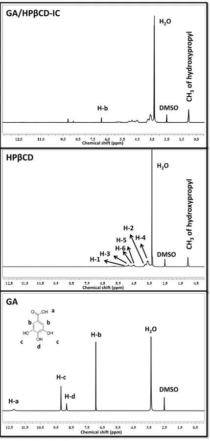
Figure 12. 1H-NMR spectra of GA, HPβCD and GA/HPβCD-IC. (Copyright ©
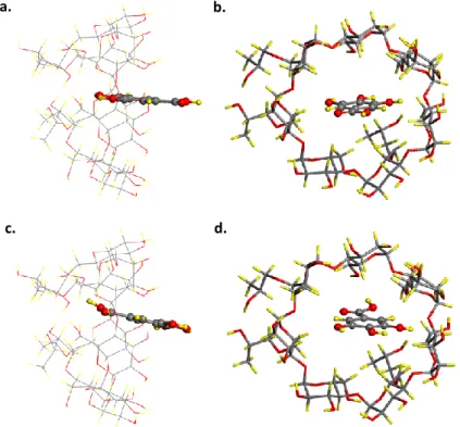
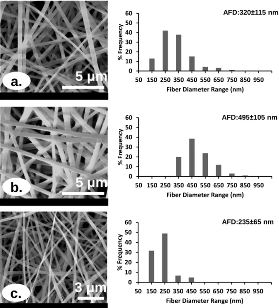
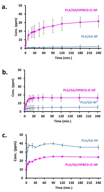
2016, Elsevier. Reprinted with permission from Ref. [117]) ... 32 Figure 13. Top and side view of GA/HPβCD-IC for (a)-(b) head and (c)-(d) tail orientation of GA. Gray, red, and yellow spheres represent carbon, oxygen, and hydrogen atoms, respectively. (Copyright © 2016, Elsevier. Reprinted with permission from Ref. [117]) ... 34 Figure 14. SEM images and fiber diameter distributions with average fiber diameter (AFD) of electrospun nanofibers obtained from solutions of (a) PLA, (b) PLA/GA, and (c) PLA/GA/HPβCD-IC. (Copyright © 2016, Elsevier. Reprinted with permission from Ref. [117]) ... 36 Figure 15. The cumulative release of GA from PLA/GA-NF and PLA/GA/HPβCD-IC-NF into (a) water, (b) 10% ethanol, and (c) 95% ethanol (n = 3). The error bars in the figure represent the standard deviation (SD). (Copyright © 2016, Elsevier. Reprinted with permission from Ref. [117]) ... 40 Figure 16. The photographs of (a) DPPH solution (before reaction); DPPH solutions in which (b) PLA-NF, (c) PLA/GA-NF and (d) PLA/GA/HPβCD-IC-NF was immersed (after reaction). (Copyright © 2016, Elsevier. Reprinted with permission from Ref. [117]) ... 42
xvii
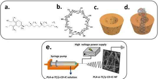
Figure 17. Chemical structure of (a) α-TC, (b) γ-CD; schematic representation of (c) γ-CD, (d) formation of α-TC/γ-CD-IC, and (e) electrospinning of
nanofibers from PLA/α-TC/γ-CD-IC solution. ... 45
Figure 18. The photographs of raw beef samples and raw beef samples packed with nanofibers in polyethylene zip bags. ... 51
Figure 19. XRD patterns of γ-CD and α-TC/γ-CD-IC. ... 52
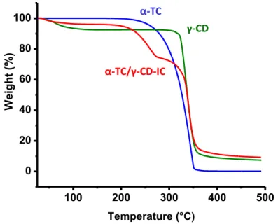
Figure 20. TGA thermograms of α-TC, γ-CD, and α-TC/γ-CD-IC. ... 53
Figure 21. 1H-NMR spectra of α-TC/γ-CD-IC. ... 54
Figure 22. SEM images of PLA-NF, PLA/α-TC-NF, and PLA/α-TC/γ-CD-IC-NF. ... 55
Figure 23. The cumulative release of α-TC from TC-NF and PLA/α-TC/γ-CD-IC-NF. ... 56
Figure 24. The photographs of (a) DPPH solution; DPPH solutions in which (b) PLA/α-TC/γ-CD-IC-NF, (c) PLA/α-TC-NF was immersed (after reaction). .... 57
Figure 25. Change of TBARS overtime during storage for raw beef meat sample (control), PLA/α-TC/γ-CD-IC-NF and PLA/α-TC-NF packed raw beef meat. . 58
Figure 26. The photographs of raw beef meat samples (control), raw beef meatsamples packed with PLA/α-TC/γ-CD-IC-NF and PLA/α-TC-NF for 28 days. ... 59
Figure 27. Chemical structure of (a) QU, (b) γ-CD; schematic representation of (c) γ-CD, (d) formation of QU/γ-CD-IC, and (e) electrospinning of nanofibers from zein/QU/γ-CD-IC solution. ... 62
Figure 28. XRD patterns of QU, γ-CD, and QU/γ-CD-IC. ... 67
Figure 29. TGA thermograms of QU, γ-CD, and QU/γ-CD-IC. ... 68
Figure 30. 1H-NMR spectra of QU/γ-CD-IC. ... 69
Figure 31. SEM images of zein-NF, zein/QU-NF, and zein/QU/γ-CD-IC-NF. . 70
Figure 32. The photographs of (a) DPPH solution; DPPH solutions in which (b) zein/QU-NF, (c) zein/QU/γ-CD-IC-NF was immersed (after reaction). ... 71
Figure 33. Chemical structure of (a) THY; (b) γ-CD; schematic representation of γ-CD, (d) formation of THY/γ-CD-IC (1:1), and (b) electrospinning of nanofibers from zein/THY/γ-CD-IC (1:1) solution. ... 73
Figure 34. XRD patterns of THY, γ-CD, IC (1:1), and THY/γ-CD-IC (2:1). ... 79
Figure 35. TGA thermograms of THY, γ-CD, CD-IC (1:1), and THY/γ-CD-IC (2:1). ... 81
Figure 36. 1H-NMR spectra of THY/γ-CD-IC (1:1) and (d) THY/γ-CD-IC (2:1). ... 82
Figure 37. SEM images of electrospun nanofibers obtained from the solutions of (a) zein, (b) zein/THY, (c) zein/THY/γ-CD-IC (1:1), (d) zein/THY/γ-CD-IC (2:1). ... 83 Figure 38. The cumulative release of thymol from (a) zein/THY-NF, (b) zein/THY/γ-CD-IC-NF (1:1), and (c) zein/THY/γ-CD-IC-NF (2:1) at 37ºC,
xviii
50ºC, 75ºC (n = 3). The error bars in the figure represent the standard deviation (SD). ... 84 Figure 39. The growth inhibition rate (%) of E. coli and S. aureus colonies in zein/THY-NF, zein/THY/γ-CD-IC-NF (1:1), and zein/THY/γ-CD-IC-NF (2:1) (n = 3). The error bars in the figure represent the standard deviation (SD). ... 86 Figure 40. The photographs of the raw meat samples; raw meat samples packed with zein/THY-NF, zein/THY/γ-CD-IC-NF (1:1), and zein/THY/γ-CD-IC-NF (2:1) and the photographs of petri dishes at the end of 1, 2 and 5 days of storage at 4°C. ... 87 Figure 41. The chemical structure of (a) HPβCD, (b) MβCD, (c) HPγCD; the schematic representation of (d) CD/geraniol-IC formation, and (e) electrospinning of nanofibers from CD/geraniol-IC aqueous solution. (Copyright © 2016, Royal Society of Chemistry. Reprinted with permission from Ref. [127]) ... 92 Figure 42. Phase solubility diagram of (a) HPβCD/geraniol, (b) MβCD/geraniol, (c) HPγCD/geraniol systems in water (n = 3). (Copyright © 2016, Royal Society of Chemistry. Reprinted with permission from Ref. [127]) ... 101 Figure 43. SEM images of electrospun nanofibers obtained from the aqueous solutions of (a) HPβCD, (b) MβCD, (c) HPγCD, (d) HPβCD/geraniol-IC, (e) MβCD/geraniol-IC, and (f) HPγCD/geraniol-IC; the photographs of (g) HPβCD-NF, (h) MβCD-HPβCD-NF, (i) HPγCD-HPβCD-NF, (j) HPβCD/geraniol-IC-HPβCD-NF, (k) MβCD/geraniol-IC-NF, and (l) HPγCD/geraniol-IC-NF webs. (Copyright © 2016, Royal Society of Chemistry. Reprinted with permission from Ref. [127]) ... 102 Figure 44. SEM image of PVA/geraniol-NF. (Copyright © 2016, Royal Society of Chemistry. Reprinted with permission from Ref. [127]) ... 103
Figure 45. 1H-NMR spectra of (a) HPβCD/geraniol-IC-NF, (b)
MβCD/geraniol-IC-NF, and (c) HPγCD/geraniol-IC-NF dissolved in d6-DMSO. (Copyright © 2016, Royal Society of Chemistry. Reprinted with permission from Ref. [127]) ... 106 Figure 46. TGA thermograms of (a) geraniol, HPβCD-NF, HPβCD/geraniol-IC-NF; (b) geraniol, MβCD-NF, MβCD/geraniol-IC-HPβCD/geraniol-IC-NF; (c) geraniol, HPγCD-NF, HPγCD/geraniol-IC-NF. (Copyright © 2016, Royal Society of Chemistry. Reprinted with permission from Ref. [127]) ... 109 Figure 47. DSC thermograms of HPβCD-NF, HPβCD/geraniol-IC-NF, MβCD-NF, MβCD/geraniol-IC-MβCD-NF, HPγCD-MβCD-NF, and HPγCD/geraniol-IC-NF; (Copyright © 2016, Royal Society of Chemistry. Reprinted with permission from Ref. [127]) ... 110 Figure 48. XRD patterns of HPβCD-NF, MβCD-NF, HPγCD-NF, HPβCD/geraniol-IC-NF, MβCD/geraniol-IC-NF, and HPγCD/geraniol-IC-NF. (Copyright © 2016, Royal Society of Chemistry. Reprinted with permission from Ref. [127]) ... 111
xix
Figure 49. FTIR spectra of geraniol, HPβCD-NF, MβCD-NF, HPγCD-NF, HPβCD/geraniol-IC-NF, MβCD/geraniol-IC-NF, and HPγCD/geraniol-IC-NF. (a) Exemplary images of Escherichia coli (E. coli), Staphylococcus aureus (S. aureus) colonies. (Copyright © 2016, Royal Society of Chemistry. Reprinted with permission from Ref. [127]) ... 112 Figure 50. The cumulative release of geraniol from (a) HPβCD/geraniol-IC-NF, (b) MβCD/geraniol-IC-NF, and (c) HPγCD/geraniol-IC-NF at 37ºC, 50ºC, 75ºC (n = 3). The error bars in the figure represent the standard deviation (SD). (Copyright © 2016, Royal Society of Chemistry. Reprinted with permission from Ref. [127]) ... 114 Figure 51. TGA of geraniol, PVA-NF, NF-1day, PVA/geraniol-NF-25day, and PVA/geraniol-NF-50day. (Copyright © 2016, Royal Society of Chemistry. Reprinted with permission from Ref. [127]) ... 116 Figure 52. (a) Exemplary images of Escherichia coli (E. coli), Staphylococcus aureus (S. aureus) colonies. The growth inhibition rate (%) and exemplary images of E. coli and S. aureus colonies treated by (b) HPβCD/geraniol-IC-NF, (c) MβCD/geraniol-IC-NF, and (d) HPγCD/geraniol-IC-NF (n = 3). (Copyright © 2016, Royal Society of Chemistry. Reprinted with permission from Ref. [127]) ... 119 Figure 53. The antioxidant activity (%) of geraniol, HPβCD-NF, MβCD-NF,
HPγCD-NF, HPβCD/geraniol-IC-NF, MβCD/geraniol-IC-NF, and
HPγCD/geraniol-IC-NF and the photographs of DPPH solutions in which geraniol, HPβCD-NF, MβCD-NF, HPγCD-NF, HPβCD/geraniol-IC-NF, MβCD/geraniol-IC-NF, HPγCD/geraniol-IC-NF were immersed, respectively. (n = 3). The error bars in the figure represent the standard deviation (SD). (Copyright © 2016, Royal Society of Chemistry. Reprinted with permission from Ref. [127]) ... 123 Figure 54. The chemical structure of (a) HPβCD, MβCD, and HPγCD, (b) the chemical structure of limonene, the schematic representation of CD and CD/limonene-IC, (c) the schematic representation of electrospinning of nanofibers from CD/limonene-IC solution. ... 126 Figure 55. Phase solubility diagram of (a) HPβCD/limonene, (b) MβCD/limonene, (c) HPγCD/limonene systems in water (n = 3). ... 134 Figure 56. (a) The chemical structure of limonene; top view of ICs of (b) HPβCD, (c) MβCD, (d) HPγCD; side view of ICs of (e) HPβCD, (f) MβCD, and (g) HPγCD with limonene in aqueous medium. Gray and yellow spheres represent carbon and hydrogen atoms, respectively. ... 136 Figure 57. SEM images of electrospun nanofibers obtained from the solutions of (a) HPβCD/limonene-IC, (b) MβCD/limonene-IC (c) HPγCD/limonene-IC; the photographs of (d) HPβCD/limonene-IC-NF, (e) MβCD/limonene-IC-NF, (f) HPγCD/limonene-IC-NF. ... 138
xx
Figure 58. The presentation of the solubility behaviour of pure limonene and HPβCD/limonene-IC-NF, MβCD/limonene-IC-NF, and HPγCD/limonene-IC-NF in water. ... 140
Figure 59. 1H-NMR spectra of (a) HPβCD/limonene-IC-NF, (b)
MβCD/limonene-IC-NF, and (c) HPγCD/limonene-IC-NF. ... 142 Figure 60. TGA thermograms of (a) limonene, HPβCD-NF, HPβCD/limonene-IC-NF; (b) limonene, MβCD-NF, MβCD/limonene-HPβCD/limonene-IC-NF; (c) limonene, HPγCD-NF, HPγCD/limonene-IC-NF. ... 146 Figure 61. DSC thermograms of HPβCD-NF, HPβCD/limonene-IC-NF, MβCD-NF, MβCD/limonene-IC-MβCD-NF, HPγCD-MβCD-NF, and HPγCD/limonene-IC-NF. ... 147 Figure 62. XRD patterns of HPβCD-NF, MβCD-NF, HPγCD-NF, HPβCD/limonene-IC-NF, MβCD/limonene-IC-NF, and HPγCD/limonene-IC-NF. ... 148 Figure 63. The cumulative release of limonene from (a) HPβCD/limonene-IC-NF, (b) MβCD/limonene-IC-HPβCD/limonene-IC-NF, and (c) HPγCD/limonene-IC-NF at 37°C, 50°C, and 75°C (n = 3). The error bars in the figure represent the standard deviation. ... 150 Figure 64. The amount of limonene in HPβCD/limonene-IC-NF, MβCD/limonene-IC-NF, and HPγCD/limonene-IC-NF at RT for 100 days. .. 151 Figure 65. Exemplary images of E. coli, S. aureus colonies. The growth inhibition rate (%) and exemplary images of E. coli and S. aureus colonies treated by limonene, HPβCD/limonene-IC-NF, MβCD/limonene-IC-NF, and HPγCD/limonene-IC-NF (n = 3). ... 153 Figure 66. (a) The chemical structure of HPβCD, MβCD, HPγCD; (b) the schematic representation of CD/linalool-IC formation, and (c) electrospinning of nanofibers from CD/linalool-IC aqueous solution. ... 156 Figure 67. SEM images of electrospun nanofibers obtained from the aqueous solutions of (a) HPβCD/linalool-IC, (b) MβCD/linalool-IC, and (c) HPγCD/linalool-IC; the photographs of (d) HPβCD/linalool-IC-NF, (e) MβCD/linalool-IC-NF, and (f) HPγCD/linalool-IC-NF webs. ... 162 Figure 68. The presentation of the solubility behaviour of pure linalool and HPβCD/linalool-IC-NF, MβCD/linalool-IC-NF, and HPγCD/linalool-IC-NF in water. ... 164
Figure 69. 1H-NMR spectra of (a) HPβCD/linalool-IC-NF, (b)
MβCD/linalool-IC-NF, and (c) HPγCD/linalool-IC-NF dissolved in d6-DMSO. ... 166 Figure 70. TGA thermograms of (a) linalool, HPβCD-NF, HPβCD/linalool-IC-NF; (b) linalool, MβCD-NF, MβCD/linalool-IC-HPβCD/linalool-IC-NF; (c) linalool, HPγCD-NF, HPγCD/linalool-IC-NF. ... 169 Figure 71. DSC thermograms of HPβCD-NF, HPβCD/linalool-IC-NF, MβCD-NF, MβCD/linalool-IC-MβCD-NF, HPγCD-MβCD-NF, and HPγCD/linalool-IC-NF. ... 170 Figure 72. XRD patterns of HPβCD-NF, MβCD-NF, HPγCD-NF, HPβCD/linalool-IC-NF, MβCD/linalool-IC-NF, and HPγCD/linalool-IC-NF.171
xxi
Figure 73. The cumulative release of linalool from (a) HPβCD/linalool-IC-NF, (b) MβCD/linalool-IC-NF, and (c) HPγCD/linalool-IC-NF at 37ºC, 50ºC, 75ºC (n = 3). The error bars in the figure represent the standard deviation (SD). .... 173 Figure 74. The amount of linalool in HPβCD/linalool-IC-NF, MβCD/linalool-IC-NF, and HPγCD/linalool-IC-NF at RT for 50 days. ... 174 Figure 75. Exemplary images of E. coli, S. aureus colonies. The growth inhibition rate (%) and exemplary images of E. coli and S. aureus colonies treated by HPβCD/linalool-IC-NF, MβCD/linalool-IC-NF, and HPγCD/linalool-IC-NF (n = 3). ... 175 Figure 76. Chemical structure of (a) curcumin; schematic representation of (b) HPβCD, (c) formation of CUR/HPβCD-IC, and (d) electrospinning of nanofibers from cCUR/HPβCD-IC-sPLA solution. ... 179 Figure 77. SEM images of electrospun nanofibers obtained from solutions of (a) PLA-CUR, (b) PLA/CUR-HPβCD-IC, (c) cCUR/HPβCD-IC-sPLA-CS; the
photographs of PLA-CUR-NF, (b) PLA/CUR-HPβCD-IC-NF, (c)
cCUR/HPβCD-IC-sPLA-CSNF. ... 185 Figure 78. (a) TEM and (b) CLSM images of cCUR/HPβCD-IC-sPLA-CSNF. ... 185 Figure 79. XRD patterns of CUR, HPβCD, PLA-NF, PLA-CUR-NF, PLA/CUR-HPβCD-IC-NF, and cCUR/HPβCD-IC-sPLA-CSNF. ... 186 Figure 80. TGA thermograms of CUR, HPβCD, PLA-NF, PLA-CUR-NF, PLA/CUR-HPβCD-IC-NF, and cCUR/HPβCD-IC-sPLA-CSNF. ... 187 Figure 81. Time dependent antioxidant activity of PLA-CUR-NF, PLA/CUR-HPβCD-IC-NF, cCUR/HPβCD-IC-sPLA-CSNF and the release of CUR from PLA-CUR-NF, PLA/CUR-HPβCD-IC-NF, cCUR/HPβCD-IC-sPLA-CSNF. 189 Figure 82. Concentration dependent antioxidant activity of PLA-CUR-NF, PLA/CUR-HPβCD-IC-NF, cCUR/HPβCD-IC-sPLA-CSNF. ... 190 Figure 83. SEM images of (a, d) PLA-CUR-NF, (b, e) PLA/CUR-HPβCD-IC-NF, (c, f) cCUR/HPβCD-IC-sPLA-CSNF after 4 (a-c) and 28 (d-f) days in vitro degradation in PBS. ... 191
xxii
LIST OF TABLES
Table 1. General properties of native CDs [56]………..………..9 Table 2. The properties of the solutions used for electrospinning and morphological characteristics of the resulting nanofibers. (Copyright © 2016, Elsevier. Reprinted with permission from Ref. [117])………37 Table 3. The composition of the solutions used for electrospinning…………...48 Table 4. The composition of the solutions used for electrospinning……...64 Table 5. The composition of the solutions used for electrospinning…………...75 Table 6. The properties of the solutions used for electrospinning and morphological characteristics of the resulting nanofibers. (Copyright © 2016, Royal Society of Chemistry. Reprinted with permission from Ref. [127])…..104 Table 7. The amount of geraniol in CD/geraniol-IC-NFs and PVA/geraniol-NF at room temperature for 50 days. (Copyright © 2016, Royal Society of
Chemistry. Reprinted with permission from Ref.
[127])……….117
Table 8. Complexation and solvation energies of limonene within HPβCD,
MβCD, and HPγCD………...137
Table 9. The properties of the solutions used for electrospinnig and morphological characteristics of the resulting nanofibers……….139 Table 10. The properties of the solutions used for electrospinning and morphological characteristics of the resulting nanofibers……….163
xxiii
LIST OF ABBREVIATIONS
1H NMR Proton nuclear magnetic resonance
ACN Acetonitrile
CD Cyclodextirn
CHCl3 Chloroform
CLSM Confocal laser scanning microscopy
CUR Curcumin
d6-DMSO Deuterated dimethylsulfoxide
DCM Dichloromethane
DMF Dimethylformamide
DPPH 2,2-diphenyl-1-picrylhydrazyl
DSC Differential scanning calorimetry E.coli Escherichia coli
FTIR Fourier transform infrared spectrometer
GA Gallic acid
HPLC High performance liquid chromatography
HPβCD Hydroxypropyl-β-cyclodextrin
HPγCD Hydroxypropyl-γ-cyclodextrin
HS GC-MS Head space gas chromatography-mass spectrocopy
IC Inclusion complex
MeOH Methanol
MβCD Methyl-β-cyclodextrin
NF Nanofiber
PBS Phosphate buffered saline
PLA Polylactic acid
xxiv
RT Room temperature
S.aureus Staphylococcus aureus
SEM Scanning electron microscopy
TEM Transmission electron microscopy
TGA Thermal gravimetric analysis
THY Thymol
XRD X-ray diffraction
1
Chapter 1
2
1.1 Electrospinning
Electrospinning has attracted considerable attention in recent years after Reneker revived attraction in 1990s [1] as a versatile method to produce nanofibers having high surface to volume ratio and highly porous structure [2, 3]. Unlike other fiber production methods it is not limited with a particular material range, thus electrospinning approach has been acknowledged universally to produce fibers from variety of materials including polymers, inorganic materials, and composites [4]. Electrospinning is capable of forming fibers in nanoscale diameters in contrast to other spinning methods including
wet spinning, dry spinning, melt spinning, and gel spinning [5]. Moreover,it is
also superior to other fiber production techniques in terms of cost, simplicity of set-up and production rate [6]. In addition to these features, design flexibility is of great significance for electrospun nanofibers [4].
Syringe pump, high voltage power supply, and grounded collector are the three main components of electrospinning set-up. The schematic view of electrospinning and our electrospinning set-up in our laboratory at UNAM is shown in Figure 1 and Figure 2, respectively. Polymer solution or melt is fed through the grounded collector at a constant rate via syringe pump. After applying high voltage from high voltage power supply, the drop in the outlet of the syringe is electrified. Due to the electrostatic repulsion and Coulombic force, the drop is transformed into a cone-shaped distortion called Taylor cone. When the electrostatic forces are high enough to overcome the surface tension of the polymer solution, jet is ejected. While jet elongates towards the grounded collector, stretching and whipping processes causes the formation of thin and
3
long fiber. As the solvent evaporates, fibers are produced in random fashion as a nanofibrous web on the collector [2, 3, 7].
Figure 1. Schematic view of the electrospinning set-up.
Figure 2. Electrospinning set-up at UNAM.
In order to obtain bead-free and uniform electrospun nanofibers, the parameters need to be optimized are divided into three groups: polymer solution parameters
High voltage power supply
Syringe pump
Electrospinning solution
15 kV
4
(type and molecular weight of the polymer; conductivity, viscosity and surface tension of polymer solution), process parameters (feed rate, applied voltage, distance between syringe and collector, diameter of the needle, collector type) and enviromental conditions (temperature and humidity) [2, 5, 8]. First of all, molecular weight and concentration of the polymer solution must provide high enough viscosity to form the chain entaglement [3]. So, if the viscosity is not sufficient to produce bead-free nanofibers, increasing the concentration may help to produce bead-free nanofibers due to the increment in the viscosity. Conductivity is another significant parameter affecting the system. If the conductivity of the polymer solution is not enough, the stretching of the solution will not be at required level to obtain nanofibers [3, 9]. Process parameters like voltage, distance, and feed rate has also an effect on the electrospinning system. High voltage is necessary for the process. Applying higher voltage results in greater stretching of the solution owing to the higher coulombic forces and electric field. Therefore, thinner diameter of fibers are obtained. Optimizing the feed rate is a critical issue for solvents to evaporate. If the feed rate is too high, solvent will remain in the nanofibers because of the lack of time. Distance between the syringe and collector has an influence on the flight time and electric field applied. Thus, when the distance is not long enough solvent will remain and cause nanofibers to merge. If the distance is too long electric field might not be enough to accelerate the jet. Lastly, temperature and humidity is of vital importance for some of the solutions. Since they are known to affect the evaporation rate of the solvent. Additionally, temperature also reduce the viscosity of the polymer solution which is a critical parameter having
5
importance for electrospinning process. On the other hand, humidity is used to achieve porous nanofibers via electrospinning [3].
In addition to basic electrospinning, it is also possible to obtain nanofibers with different morphology such as aligned, core-shell, hollow and porous nanofibers. In an electrospinning set-up, nanofibers are collected randomly on a fixed grounded collector. However, using a cylindrical rotating collector instead of a fixed one enables to yield aligned nanofibers [10, 11]. Employing core-shell nozzle (Figure 3) will result in formation of core-shell nanofibers [12, 13]. Furthermore, it was also reported the production of core-shell nanofibers by using electrospinning and atomic layer deposition [14]. In order to obtain hollow nanofibers, the core part of the core-shell nanofibers is removed [15, 16]. Electrospun nanofibers have intra-fiber pores, however achieving the nanofibers having pores on the nanofiber is also possible via electrospinning [17, 18].
Figure 3. The photograph of core-shell nozzle and schematic representation of
electrospinning of core-shell nanofibers. core-shell nanofibers shell solution
6
Electrospun nanofibers can be used in many areas in which high surface to volume ratio is a significant characteristic desired. Highly porous structure is another advantage of electrospun nanofibers which makes them excellent candidate for many other applications. As mentioned above, flexibility of the system is also important for universality since nanofibers having different morphology might be obtained using electrospinning with slight modifications [19, 20]. Other than the exceptional characteristics of electrospun nanofibers, its ease of functionalization with number of molecules further extends its application areas [4]. For example, nanoparticles [21, 22], inorganic precursors [23, 24], drugs [25, 26], antioxidant [27, 28] and antibacterial agents [29, 30], food additives (essential oils, flavour/fragrance) [31-33] can be incorporated in electrospun nanofibers in one step. Consequently, electrospun nanofibers find application in filtration [34-36], biomedical [29, 37-41], food and agriculture [42-45], enzyme and catalyst [46-49], sensor [50-52], energy and electronics [53-55] (Figure 4).
7
Figure 4. Application areas of electrospun nanofibers.
1. 2 Cyclodextrins
Cyclodextrins (CDs) are nontoxic cyclic oligosaccharides composed of six, seven, eight or more glucopyranose units and linked by α-(1,4) bonds [56, 57]. When Villiers first discovered CDs in 1891, he named them as “cellulosine” due to their structural resemblance to cellulose [56]. Since Schardinger has a significant role to elucidate the chemistry of CDs in the early 1900s, CDs are also called as Schardinger dextrins [56, 57]. CDs are produced from starch or its derivates by using CD glycosyltransferase (CGTase) of various microorganisms including Bacillus macerans, Klebsiella oxytoca, Bacillus circulans, and Alkalophylic bacillus [56]. However, isolation needs to be done to obtain each CD from the mixture obtained at the end of the enzymatic degradation. For
Food/Agriculture Filtration Enzyme/Catalyst Energy/Electronics Biomedical Sensor
8
instance, if toluene is used β-CD is produced due to the formation of inclusion complex (IC) between toluene and β-CD [56]. The three major and most widely used CDs are α-CD, β-CD, γ-CD and consist of 6, 7, and 8 glucopyranose units, respectively (Figure 5) [56-58]. The properties of native CDs are summarized in Table 1. The volume of the cavity is increasing from α-CD to γ-CD. The solubility of β-CD is quite low compared to α-CD and γ-CD, due to the complete secondary belt formation via hydrogen bonds. α-CD can only form four hydrogen bond instead of six because of the distorted position of one glucopyranose unit. The higher solubility of γ-CD is most likely owing to its noncoplanar and more flexible structure [56]. Native CDs (α-CD, β-CD, and γ-CD) can also be modified to obtain CD derivatives. According to the type of functional group substituted to hydroxyl groups in native CDs, hydrophilic or hydrophobic derivatives are achieved. While producing CD derivatives, the main purpose is increasing the solubility, complexation ability and stability against light or oxygen compared to native CDs [56, 57]. In addition to the changes in the solubility, the cavity volume of native CDs are also being modified in CD derivatives [57].
9
Figure 5. Chemical structure and schematic view of α-CD, β-CD, and γ-CD
[56].
Table 1. General properties of native CDs [56].
As seen from the chemical structure of CDs in Figure 6, there exist two types of hydroxyl groups (primary and secondary) in the structure. Primary hydroxyl
Properties α-CD β-CD γ-CD
Number of glucopyranose units 6 7 8
Molecular weight (g/mol) 972 1135 1297
Outer diameter (Å) 14.6 15.4 17.5
Cavity diameter (Å) 4.7-5.3 6.0-6.5 7.5-8.3
Height of torus (Å) 7.9 7.9 7.9
Approximate cavity volume (Å3) 174 262 427
10
groups (C6) are in the narrower edge, whereas secondary hydroxyl groups (C2 and C3) are located in the wider edge of CDs. Due to the steric arrangement CDs has truncated-cone shape structure with hydrophilic outside surface and relatively hydrophobic cavity in which apolar C3 and C5 hydrogens and ether-like oxygens are present [56-58]. The distinct character of CDs is related with their relatively hydrophobic cavity residing various types of molecules in appropriate polarity and dimension [56-58]. Thus, they are capable of making non-covalent host-guest ICs with solid, liquid, and gaseous compounds [56-58].
Figure 6. (a) Chemical structure of HPβCD, MβCD, and HPγCD, (b) schematic
representation of the primary and secondary rim of CD molecules.
Complex formation is occurred when there is a dimensional and polarity fit between host and guest molecules (Figure 7). The main driving force of this phenomena is the replacement of enthalpy-rich water molecules from cavity by the apolar guest molecules. So, repulsive forces between water molecules and cavity and bulk water and guest molecule are main components of the driving force. So, CD-ICs decrease the ring strain of CDs and more stable lower energy state is obtained. Weak forces, such as van der Waals interactions, dipole-dipole interactions, hydrophobic interactions and hydrogen bonding play role in the formation of the complexes. Among several methods of producing CD-ICs
co-R=CH2CH(OH)CH3 or H R=CH3or H 8 7 7 R=CH2CH(OH)CH3 or H secondary rim primary rim HPβCD MβCD HPγCD a. b.
11
precipitation, slurry, paste, and dry mixing are the most widely used methods. However, co-precipitation is a common technique in laboratory scale [58]. In the simplest case, one guest molecule is held by one host (CD) molecule. However, two or more CD molecules might host one guest molecule or one CD molecule might reside two or more guest molecules [56, 57].
Figure 7. Schematic view of IC formation between guest and CD molecule.
Inclusion complexation leads to various modifications in the properties of the guest molecule such as converting liquid molecules to powder form [59-61], enhancement the solubility [62-64], stabilization against light [65, 66], oxygen [67], etc., reducing the volatility [68-71], controlling fluorescence and light absorption [72, 73]. Therefore, CDs find a broad application areas in filtration [74-78], pharmaceutical [79-82], food [83-88], cosmetic [89, 90], and personal care [91] industries.
1.3 Electrospun nanofibrous webs as carrier for
bioactive compounds
Bioactive compounds used in pharmaceutical and food industry have some limitations. The majority of these substances is problematic in terms of their low aqueous solubility, poor bioavailability, and sensitivty against various means
12
such as light, oxygen, temperature etc. These limitations increase the required dose and reduce the shelf life of these molecules [92, 93]. In addition, degradation of these products might produce off-flavors, off-colors, or carcinogenic compounds that is also not a desired feature of the products [92]. Therefore, encapsulation methods are used to overcome the limitations of these active agents with maintaining their biological activity [92]. Among several encapsulation methods, complexation with CDs is an effective approach. Since CD-ICs improve the solubility of bioactive molecules to reduce the required concentration for showing the biological effect and protect them from light, oxygen, temperature to prolong the shelf life of products [93].
On the other hand, electrospinning has gained interest as a universal method to produce functional nanofibers for applications in food packaging and drug delivery as mentioned previously. Since electrospun nanofibers offer advantages over films, they are superior to films. First, electrospinning system enables to produce nanofibers at room temperature in contrary to polymeric films which are usually produced at high temperatures. Therefore, encapsulation of essential oils and flavour/fragrances which are mostly volatile into electrospun nanofibers are a better alternative [31]. Secondly, nanofibers are responsive to changes such as relative humidity and temperature which enables tunable release of the active agents incorporated. Additionally, various compounds including drugs [25, 26], antioxidant [27, 28] and antibacterial agents [29, 30], and food additives [31-33] might be incorporated into electrospun nanofibers in one step.
Combinining the synergetic effect of CD-ICs of bioactive agents with electrospun nanofibers is a new approach [94]. This approach has been applied
13
by our group in order to use several bioactive agents in a more efficient way
[95-105].There are also other studies in the literature following our approach in
which IC of various molecules and CD types are included in many types of polymeric nanofibers [106-116]. Contribution of this thesis (Chapter 2) in “CD-IC incorporated polymeric nanofibers” area is the investigation of application of these nanofibers as packaging and delivery material [117].
In general, polymers have been taken as a material/matrix for the fabrication of nanofibers owing to the chain entanglement and overlapping between the polymer chains [118]. However, Celebioglu and Uyar successfully demonstrated the electrospinning of polymer-free nanofibers from various native and modified CDs without using any polymeric carrier matrix [119-123]. The self-assembly and aggregation characteristics of CD molecules in concentrated solutions via the formation of intermolecular hydrogen bonding enables the production of nanofibers in the absence of polymer matrix. Further, CD-IC nanofibers of triclosan was produced by our group [124, 125]. But, these studies were mostly focused on the production of CD-IC nanofibers except investigating antibacterial activity. Our research group also produced CD-IC incorporated polymeric nanofibers successfully as mentioned above [95-105, 117]. Yet, sometimes the necessity of using organic solvents which generally have environmental hazards might not suitable for applications including pharmaceutical and food packaging. However, usage of organic solvents might be unavoidable in the fabrication of some nanofibers. Therefore, water soluble molecules like CDs could be an alternative molecule to produce nanofibers. In addition, electrospinning of polymer-free CD-IC nanofibers having much higher
14
loading capacity of guest molecules (up to ~ 10-15%, w/w) as compared to CD-IC incorporated polymeric nanofibers were quite successfully and electrospinning was performed in aqueous solution [124, 125]. Therefore, polymer-free CD-IC nanofibers may open up new possibilities for various
applications including cosmetic, biomedical, food packaging, and
flavour/fragrance releasing. Recently, CD-IC nanofibers of vanillin was also produced by electrospinning [126]. Contribution of this thesis (Chapter 3) in “Electrospinning of CD-IC nanofibers” research is the application of these concept to flavour/fragrances and investigating of these nanofibers as a releasing nanoweb [127].
Production of core-shell nanofibers can be done in two step [14, 128]. However, core-shell nanofibers obtained via electrospinning system having a special nozzle (Figure 3) is a one step process and it is one of the most interesting structure which can be produced by using electrospinning. Core and shell solutions could be both miscible and immiscible depending on the solvents used [129]. The solution can be fed through to colllector by two separate syringe pumps or pressurized gas [129]. The parameters which affect the monoaxial electrospinning is of importance for coaxial electrospinning as well. But in this case, the miscibility of the solvents used in core and shell solutions is a critical issue that must be considered. For example, using chloroform and water may result in formation of pendant droplets in the edge of the nozzle. However, using an intermediate solvent like methanol or ethanol might be helpful due to their miscibility with both of the solvents and low surface energy [129]. Flow rate ratio of core and shell solutions is of significance as well. Thus, if the flow rate
15
ratio less than 1:2 (core:shell) shell solution might not encapsulate the core solution; whereas if the ratio is high there will be a risk of producing nanofibers composed of only shell solution [129]. Core-shelll nanofibers is of particular interest for non-spinnable systems, if one uses non-spinnable solution or even a powder and polymer solution in the core and shell, respectively. This is regarding with the internal (viscous and viscoelastic) stresses and Maxwell stresses present in such kind of a system [12, 130]. It was reported that core-shell nanofibers can be employed in order to protect sensitive bioactive agents against light and organic solvents caused by the direct contact with these means, and produce electrospun nanofibers which has unique properties such as high surface to volume ratio and porous structure. Furthermore, core-shell nanofibers developed for drug delivery might provide a better control over the release of the drug. Since the shell acts as an additional barrier for the release of drugs. It is also facile to play with the type of the polymer used, thickness of the shell and core fibers, encapsulated drug which can be both hydrophilic and hydrophobic. Lastly, the system is also available for encapsulation of more than one drug to the nanofibers for in-situ applications. On the other hand, there exist some limitations about the coaxial electrospinning. Common drawbacks of the system can be the difficulty in concentricity of the core and shell parts of the nanofibers and production of hollow nanofibers due to the non-continuous core entrainment [131]. In the literature, coaxial electrospinning is used in many application areas including delivery of growth factors [132], gene [133], protein [134], living organisms such as cell [135], virus [136], bacteria [137] in biomedical; food packaging [138, 139], enzyme/catalyst [140, 141], filtration [142, 143], sensor
16
[144, 145], and lithium-ion batteries [146], supercapacitors [147], [148] in energy/electronics. However, there is no study on the fabrication of core-shell nanofibers by using CD-IC solution in the shell. So, core-shell nanofibers obtained by CD-IC and polylactic acid serve as a leading study for the electrospinning literature. Contribution of this thesis (Chapter 4) to “core-shell nanofibers“ area is the production of new generation of core-shell nanofibers from CD-ICs for the first time.
In this thesis, electrospinning of cyclodextrin functionalized nanofibers were produced according to three different methods. Firstly, the studies are focused
on the incorporation of CD-ICs of bioactive compounds
(antioxidant/antibacterial agents) into electrospun polylactic acid or zein nanofibers for packaging and delivery applications (Chapter 2). Then, the production of electrospun nanofibers from CD-ICs of flavour/fragrances without using a polymer matrix was achieved and the release and shelf life of these molecules were investigated (Chapter 3), and finally, core-shell nanofibers were obtained by using CD-IC solution of an antioxidant (curcumin) in the core and polylactic acid solution in the shell for the first time (Chapter 4).
17
Chapter 2
ENCAPSULATION OF CYCLODEXTRIN
INCLUSION COMPLEXES IN
ELECTROSPUN POLYMERIC
NANOFIBERS
(Parts of this study was published as “Encapsulation of gallic acid/cyclodextrin inclusion complex in electrospun polylactic acid nanofibers: Release behavior and antioxidant activity of gallic acid”, Zeynep Aytac, Semran Ipek Kusku, Engin Durgun, Tamer Uyar*, Materials Science and Engineering C, June 1, 2016 (Web), Reproduced (or 'Reproduced in part') from Ref. [117] with permission from Elsevier doi:10.1016/j.msec.2016.02.063)
18
2. Encapsulation of gallic acid/cyclodextrin inclusion
complex in electrospun polylactic acid nanofibers:
Release behavior and antioxidant activity of gallic acid
2.1 Introduction
Phenolic compounds are the most common primary antioxidants to readily scavenge free radicals by donating hydrogen atom or an electron [149]. Gallic acid (GA) (Figure 8a) is a hydroxybenzoic acid and considered as a natural phenolic antioxidant and antimicrobial agent. GA and its derivatives including tannins and catechin are especially found in berries, citrus fruits, cereals, tea, wine and herbs [150]. Since it has antioxidant and antimicrobial activity, it is used as an additive in food, cosmetics and pharmaceutical industry [151-154]. However, it might easily oxidize which further leads to degradation. In order to protect GA against degradation and maintain its bioactivity against external and environmental factors, cyclodextrin (CD) (Figure 8b-c) inclusion complex (CD-IC) has been synthesized and considered to be an efficient system in recent years [155, 156]. Therefore stabilization of GA might be improved by an encapsulation technique, inclusion complexation.
Flexibility of electrospinning process enables to obtain nanofibers containing active agents which have potential to be used in diverse application areas. Therefore, active agent encapsulated polymeric films and electrospun nanofibers have been studied previously [151, 153, 157]. CD-ICs can be incorporated into polymeric films and then CD-IC functionalized polymeric films might be used in food packaging and pharmaceutical applications [158, 159]. However, designing delivery systems for food packaging and drug delivery applications by
19
using nanofibers is advantageous over films owing to the high surface area and highly porous structure. In one of our previous study, sulfisoxazole (SFS)/CD-IC incorporated hydroxypropyl cellulose (HPC) nanofibers (HPC/SFS/CD-(SFS)/CD-IC- (HPC/SFS/CD-IC-NF) and films (HPC/SFS/CD-IC-film) were produced. The release of SFS was much more but slower from HPC/SFS/CD-IC-NF as compared to HPC/SFS/CD-IC-film. Low surface area of HPC/SFS/CD-IC-film and close location of SFS to the surface in HPC/SFS/CD-IC-film was stated the reason of less amount and quick release of SFS from HPC/SFS/CD-IC-film [103].
Polylactic acid (PLA) is biodegradable aliphatic polyester produced from lactic acid and well suited for food packaging and drug delivery applications owing to its biocompatibility, biodegradability; carbon dioxide, oxygen and water permeability, and light barrier properties [160]. Leading studies related to incorporation of CD-IC of various guest molecules into electrospun nanofibers were reported by our research group [95-105, 117].
20
Figure 8. Chemical structure of (a) GA, (b) HPβCD; schematic representation
of (c) HPβCD, (d) formation of GA/HPβCD-IC, and (e) electrospinning of nanofibers from PLA/GA/HPβCD-IC solution. (Copyright © 2016, Elsevier. Reprinted with permission from Ref. [117])
In this part, inclusion complex of GA and HPβCD (GA/HPβCD-IC) (Figure 8d) was formed and then it was incorporated into PLA nanofibers (PLA/GA/HPβCD-IC-NF) by electrospinning technique (Figure 8e). The prepared GA/HPβCD-IC was characterized by using phase solubility, X-ray diffraction (XRD), thermal gravimetric analysis (TGA), and proton nuclear
magnetic resonance (1H-NMR). Computational modeling studies were also
performed to investigate complexation in vacuum and in aqueous system. GA incorporated PLA nanofibers without HPβCD (PLA/GA-NF) were taken as a control sample. The morphological characterization of PLA/GA-NF and PLA/GA/HPβCD-IC-NF were carried out by scanning electron microscope (SEM). The release of GA from PLA/GA/HPβCD-IC-NF and PLA/GA-NF was determined in aqueous solution, 10% ethanol, and 95% ethanol by high
b.
R=CH2CH(OH)CH3a.
R=CH2CH(OH)CH3c.
d.
Syringe pump
High voltage power supply
PLA/GA/HPβCD-IC solution PLA/GA/HPβCD-IC-NF
21
performance liquid chromatography (HPLC). The antioxidant activity of the GA present in PLA/GA/HPβCD-IC-NF and PLA/GA-NF was evaluated using 2,2-diphenyl-1-picrylhydrazyl (DPPH) radical scavenging method.
2.2 Experimental
2.2.1 Materials
Polylactic acid (PLA) was donated by Natureworks (product code 6252D). Gallic acid (GA, ≥97.5-102.5%, Sigma Aldrich), hydroxypropyl-beta-cyclodextrin (HPβCD, Wacker Chemie AG, Germany), methanol (extra pure, Sigma Aldrich), ethanol (99.8%, Sigma Aldrich), dichloromethane (DCM, extra pure, Sigma Aldrich), N,N-dimethylformamide (DMF, ≥99%, Sigma Aldrich), acetonitrile (ACN, chromasol, Sigma Aldrich), deuterated dimethylsulfoxide (DMSO-d6, deuteration degree min 99.8% for NMR spectroscopy, Merck), 2,2-diphenyl-1-picrylhydrazyl (DPPH, Sigma Aldrich) were purchased and used as-received without any further purification. Distilled-deionized water was supplied from Millipore milli-Q ultrapure water system.
2.2.2 Preparation of inclusion complex and physical mixture
The formation of solid GA/HPβCD-IC was prepared according to slurry method. Initially, GA was dissolved in aqueous solution; then HPβCD was added and the mixture was stirred for 2 hours at 70°C. The mixture was kept in hood for 2 days and the resulting white powder was crashed in agate mortar. The molar ratio of GA:HPβCD was used as 1:1. GA/HPβCD-PM was obtained by mixing GA and HPβCD in a glass mortar at a molar ratio of 1:1.22
2.2.3 Preparation of electrospinning solutions
Free GA and GA/HPβCD-IC incorporated PLA nanofibers (PLA/GA-NF and PLA/GA/HPβCD-IC-NF) were produced via electrospinning technique. For this purpose, Free GA (5%, w/w, with respect to polymer) was dissolved in DCM:DMF (7:3) at room temperature (RT). Then, 10% PLA (w/v) was added and PLA/GA solution was stirred for 2 hours before electrospinning. With regards to PLA/GA/HPβCD-IC-NF; GA/HPβCD-IC (5% GA, w/w, with respect to polymer) was dispersed in DCM:DMF (7:3) at RT. Afterwards, 10% PLA (w/v) was added, PLA/GA/HPβCD-IC solution was stirred 2 hours prior to electrospinning. The vials were covered with a piece of aluminum foil during stirring to avoid any potential light effect for GA. As a reference sample, we have also electrospun 10% PLA solution (w/v) prepared in DCM:DMF (7:3). Table 2 summarizes the composition of the PLA, PLA/GA and PLA/GA/HPβCD-IC solutions and the morphological findings of PLA-NF, PLA/GA-NF and PLA/GA/HPβCD-IC-NF.
2.2.4 Electrospinning
PLA, PLA/GA and PLA/GA/HPβCD-IC solutions loaded into 3 ml plastic syringe with a needle inner diameter of 0.8 mm were placed horizontally on the pump. The solutions were sent towards to the collector at 1 ml/h rate by syringe pump (KD Scientific, KDS101). 15 kV was applied from a high voltage power supply (AU Series, Matsusada Precision Inc.). Cylindrical metal covered with aluminum foil was used as a collector. Distance between needle tip and collector was 10 cm. Experiments were performed at 24-25°C, 17-18% humidity.
23
2.2.5 Characterizations and measurements
Phase solubility measurements were performed in aqueous solution according to the method of Higuchi and Connors [161]. Excess amount of GA was added to 10 mL of water containing HPβCD (ranging from 0 to 0.016 M). The equilibrium was achieved by stirring the solutions for 12 hours at RT, the suspensions were filtered through 0.45 µm membrane filter to remove undissolved solid. GA concentration was determined spectrophotometrically at 259 nm (Varian, Cary 100). The stability constant (KS) of the complex was
calculated from the phase solubility diagram according to the following equation:
Ks=slope/S0(1-slope) (Equation 1)
where S0 is the solubility of GA in the absence of HPβCD. The phase diagram is
a plot of the molar concentration of GA versus molar concentration of HPβCD.
The crystalline structure of powder of GA, HPβCD, GA/HPβCD-IC and GA/HPβCD-PM were recorded via X-ray diffraction (XRD, PANalytical X’Pert powder diffractometer) applying Cu Kα radiation in a 2θ range 5°-30°.
Thermal gravimetric analysis (TGA, TA Q500, USA) was used to investigate the thermal properties of GA, HPβCD, GA/HPβCD-IC and GA/HPβCD-PM in high resolution TGA mode (dynamic rate). The measurements were carried out under nitrogen atmosphere, and the samples were heated up to 500°C at a constant heating rate of 20°C/min.
24
The proton nuclear magnetic resonance (1H-NMR) spectra were recorded on
Bruker DPX-400 at 400 MHz. 10 mg of GA, HPβCD and GA/HPβCD-IC was dissolved in 0.5 mL of d6-DMSO to evaluate the molar ratio of GA/HPβCD-IC. Integration of the chemical shifts (δ) given in parts per million (ppm) was calculated by using Mestrenova software.
In order to investigate how the solution parameters affect the diameter of nanofibers, viscosity and conductivity measurements were done at RT. The viscosity of PLA, PLA/GA and PLA/GA/HPβCD-IC solutions were analyzed via Anton Paar Physica MCR 301 rheometer equipped with a cone/plate accessory (spindle type CP40-2) at a constant shear rate of 100 1/sec and the conductivity of the above-mentioned solutions was measured with Inolab 720-WTW.
The morphology of PLA-NF, PLA/GA-NF and PLA/GA/HPβCD-IC-NF was investigated by scanning electron microscopy (SEM, FEI-Quanta 200 FEG). Samples were mounted on metal stubs with double-sided adhesive copper tape and coated with 5 nm Au/Pd (PECS-682). Average fiber diameter (AFD) of the nanofibers was calculated from the SEM micrographs. At least 100 fibers were measured for each sample, and their averages and standard deviations were reported.
The cumulative amount of released GA from PLA/GA-NF and
PLA/GA/HPβCD-IC-NF were measured via high performance liquid chromatography (HPLC, Agilient, 1200 series) equipped with VWD UV detector and the detection was accomplished at 259 nm. Nanofibers (20 mg)
25
were individually immersed in 30 ml of aqueous solution, 10% ethanol and 95% ethanol and the solutions were stirred at RT at 50 rpm for 4 hours. The three medium were used to observe the release of GA in mediums having different polarity. 0.5 ml of sample solution was withdrawn at specified time intervals and an equal amount of fresh medium was refilled. The diol column (250 mm x 4.6 mm i.d., 5μm, Inertisil GL Sciences Inc.) operating at 1 ml/min with ACN:water (50:50) eluent was used for chromatographic separation. The calibration curves were obtained by dissolving GA in aqueous solution, 10% ethanol and 95% ethanol. The cumulative amount of GA released from nanofibers was converted to concentration (ppm) according to the calibration curves. The experiments were performed in triplicate and the results were reported as average values±standard deviation. The loading efficiency (LE) (%) of PLA/GA-NF and PLA/GA/HPβCD-IC-NF were determined by dissolving certain amount of nanofiber in DCM:DMF (7:3) and the amount of GA in the nanofiber was determined by HPLC using the calibration curve obtained in DCM:DMF (7:3) in triplicate. Finally, loading efficiency (%) was calculated according to the following equation:
Loading efficiency (LE) (%) = Ce/Ct x100 (Equation 2)
where Ce is the concentration of encapsulated active compound and Ct is the
total concentration of active compound.
Antioxidant tests for PLA-NF, PLA/GA-NF and PLA/GA/HPβCD-IC-NF were performed via 2,2-diphenyl-1-picrylhydrazyl (DPPH) radical scavenging assay.
The nanofibers having equivalent amount of GA were immersed in 3 ml of 10-4
![Figure 5. Chemical structure and schematic view of α-CD, β-CD, and γ-CD [56].](https://thumb-eu.123doks.com/thumbv2/9libnet/5688514.114826/33.892.263.694.130.413/figure-chemical-structure-schematic-view-cd-cd-cd.webp)