Slow Plasmons in Grating Cavities
Atilla Aydinli
a*, Ertugrul Karademir
b, Sinan Balci
c, and Coskun Kocabas
aa
Department of Physics, Bilkent University, 06800 Ankara, Turkey
b
School of Physics and CRANN, Trinity College Dublin, College Green, Dublin 2, Ireland
cDepartment of Astronautical Engineering, University of Turkish Aeronautical Association,
06790 Ankara, Turkey
*[email protected]
Keywords: Surface Plasmon Polaritons, Plasmonic Cavities, Slow Light, Plasmon-Exciton Coupling,
Plasmonic Laser, Light Matter Interaction
ABSTRACT
Recent research on surface plasmon polaritons and their applications have brought forward a wealth of information and continues to be of interest to many. In this report, we concentrate on propagating surface plasmon polaritons (SPPs) and their interaction with matter. Using grating based metallic structures, it is possible to control the electrodynamics of propagating SPPs. Biharmonic gratings loaded with periodic Si stripes allow excitation of SPPs that are localized inside the band gap with grating coupling, [1]. The cavity state is formed due to periodic effective index modulation obtained by one harmonic of the grating and loaded Si stripes. More complicated grating structures such as metallic Moiré surfaces have also been shown to form a localized state inside the band gap when excited with Kretschmann configuration, [1-6].
1. INTRODUCTION
Surface plasmon polaritons (SPPs), arising from coupling of electromagnetic incident waves to plasma oscillations in metals, are electromagnetic surface waves propagating at the interface between a metal and a dielectric air interface with an exponentially decaying electric field intensity into both dielectric and metal films. On flat metal surfaces, the SPPs show propagating properties whereas on metal nanoparticles or nanostructured metal thin films, for example plasmonic cavities, they demonstrate localized behaviors and thus they are called localized SPPs on these structures. SPPs show slow group velocities on plasmonic cavities. Decreasing group velocity of SPPs is appealing because, in this way, variety of optical processes at the nanoscale dimension are enhanced and hence performance of the plasmonic devices can be greatly boosted. Finding a suitable plasmonic structure with an optimized optical properties is always the goal of plasmonic field. In order to achieve this goal, variety of plasmonic nanostructures using bottom up and top down approaches have been fabricated and extensively studied. In this study, we demonstrate that metallic Moiré surfaces containing plasmonic coupled cavities are very good candidate for this aim and we propose that it can be a model nanostructure for achieving this goal.
Invited Paper
Slow Light, Fast Light, and Opto-Atomic Precision Metrology IX, edited by Selim M. Shahriar, Jacob Scheuer, Proc. of SPIE Vol. 9763, 97630Z · © 2016 SPIE
CCC code: 0277-786X/16/$18 · doi: 10.1117/12.2220199 Proc. of SPIE Vol. 9763 97630Z-1
The Moiré surfaces were fabricated by using holographic Interference Lithography (IL). 170 μm thick glass substrate was firstly coated with an anti-reflection coating BARLI (Microchem) and then uniformly coated with a photosensitive polymer S 1800-4 (Microchem). The fabricated samples were exposed in IL set up using a collimated He-Cd laser beam of 325 nm wavelength. Interference fringes were formed on the photoresist thin film. Subsequently, the exposed photoresist layer was developed in a solution of AZ 400 K (developer). In IL set up, sequential exposure at slightly different illumination angles creates Moiré surface pattern on the photoresist polymer surface, see Figures 1(a) and 1(b) for the atomic force microscopy and scanning electron microscopy images of the Moiré surfaces, respectively. The Moiré surface was coated with a thin Ag film layer, e.g. 50 nm, to support excitation of SPPs. Polarization dependent optical reflection as a function of the incidence angle and wavelength measurements were performed in the TM mode using spectroscopic ellipsometer-WVASE32 (J. A. Woolam Co., Inc., USA) in the visible and near infrared spectra. It is noteworthy to mention here that reflection measurements with TE mode did not yield SPPs on the thin metal films. The optical measurements were performed in the Kretschmann configuration by attaching the metallic Moiré surfaces onto a prism using index matching fluid where the reflection losses were eliminated with the help of index matching fluid. All finite difference time domain (FDTD) simulations were done by using commercial software (Lumerical). We used a cyanine dye [5,5 ,6,6 -tetrachloro-di-(4-sulfobutyl) benzimidazolocarbocyanine, TDBC, from Few Chemicals to study plasmon-exciton coupling on flat and nanostructured metal films. At high concentration, TDBC dye molecules forms J-aggregate nanostructures which is identified by narrowing and redshifting of the monomer absorption spectrum. TDBC molecules were dissolved in an aqueous solution of polyvinyl alcohol (PVA) and the solution was then spin coated at 3000 rpm onto the metal thin films. The details about the plasmonic laser measurements were reported in our previous work, [5].
3. RESULTS AND DISCUSSION
Polarization dependent spectroscopic reflection measurements revealed that group velocity of SPPs on plasmonic coupled cavities can be tuned by adjusting: i) grating groove depth, ii) cavity size, iii) thickness of the metal film, and iv) dielectric loading, [2, 6]. When the cavity size is large, the SPPs are localized (standing waves resonators) inside the plasmonic cavities and the group velocity of the SPPs approaches to zero. Conversely, when the cavity size is very small the group velocity of SPPs is very large and they are propagating (travelling wave resonators). The plasmonic coupled cavities on metallic Moiré surfaces can be considered to be an analog of coupled resonator optical waveguides (CROWs), [6]. The dispersion of the SPP cavity mode can be described as
( ) = [1 + cos ( )]
where Ω, κ, and D are the plasmon resonance frequency of the cavity, coupling coefficient, and cavity size, respectively. The group velocity of the SPP modes can be expressed as
( ) = ( )= − sin ( ) 2. EXPERIMENTAL
(a)
(b)
(C) 0.30 0.25 0.20 -U co 0.15J
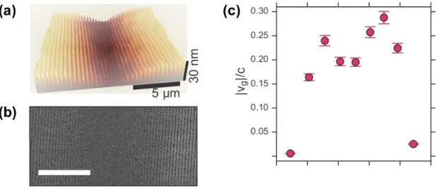
0.10 0.05-Figure 1. (a) AFM image of a Moiré 250+256 nm cavity. (b) SEM image of the same cavity. (c) Group velocity dispersion of the SPP mode inside the cavity.
It is obvious from the above equation that the group velocity of the SPPs strongly depends on the cavity size, and coupling coefficient. Thus, the group velocity of SPPs can be calculated from the slope of the dispersion curve, Figure 1(c). Additionally, at the band edges the group velocity of SPPs are greatly reduced. We then turned our attention to the tuning plasmon-exciton coupling on plasmonic coupled cavities and flat
metal surfaces. SPPs of plasmonic cavities and flat meta l surfaces and excitons of J-aggregate TDBC molecules
are combined in order to investigate coupling between them in the weak and strong coupling regimes.
5 μm
1.21 1.22 1.23 1.24 1.25 1.26
0.00
Wave Number (m
-1)
x10 7
'SC ioa Figure 2. experime n The con c energy i n to the sq u the stud y aggregat e enabled u [3]. (a) Thickness n t. (d) FWHM o c entration of t h n plasmon-ex c u are root of t y , the thickne s e molecules h u s to probe t h tuned reflecti o o f splitting. h e J-aggregat c iton couplin g t he dye conce s s of the met a h as been ext e h e plasmon-e x o n maps. (b) C ed TDBC mo g . The results ntration whic a l film has be e e nsively inve s x citon coupli n C oupling energ y lecules are v a have showe d h is supporte d e n varied and s tigated. Cont r n g from wea k y as a functio n a ried in order t that Rabi sp l d by analytic a the coupling r olling the pl k ly coupling r n of silver thic k t o observe va r l itting energy a l calculation s between the S asmonic loss r egime to str o k ness, simulat i r iation of Ra b is linearly pr o s . In the seco n S PPs and exc i in thin meta l o ngly coupli n i on and (c) b i splitting o portional n d part of i tons of J-l fiJ-lm has n g regime,
(x`i55ti` , í#P
41,~04,071~4
tmemomemo (a) io os E 30o T13:1=
4141mmm~6e - ó -0.5 00 05 x(pm) 10 (b) 90° 135° .i.i.i. 45. .
.. . .. 180 225 .: :. \41. r'%
r ' . 4 .,'.t.4
270° 15° Plexcitonic Region Bare Excitonic Region- Exciton Line
Lower Band Edae
0° (c) 75 Ñ E 60 >. rT c 45 W co c 30
ñ
1n 15 0 5 10 15 20 25 Azimuth Angle ( °) 30Figure 3. (a) SEM micrograph of a square lattice plexcitonic crystal, the inset is mathematical model. Periodicity of the
crystal is 280 nm in both directions. (b) Directional coupling and uncoupling dependenc e of the same crystal with band edge wavelengths. The crystal shows, square rotational symmetry. (c) Splitting energy, related to the coupling strength between
excitons and SPPs. At 15° ex citons and SPPs are uncoupled.
Using IL technique, it is possible to fabricate 2-dimensional plasmonic crystals. These structures have been characterized using variety of techniques, Figure 3. Another way of studying plasmon-exciton coupling is
locating self-assembled TDBC molecules in PVA matrix on 2-dimensional plasmonic crystals. Without altering the composition of the plasmonic thin film or the J-aggregated TDBC molecules in PVA polymer it is possible
to tune plasmon-exciton coupling on this crystals and henc e we called this crystal as plexcitonic crystals, [1, 4].
Plexcitonic Region Bare Excitonic Region Exciton Line Upper Band Edgeoe addge
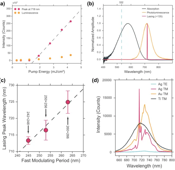
Figure 4. Demonstration of plasmonic lasing. (a) shows the intensity of the peak at 718 nm for various pump energy densities. In (b) absorption and photoluminescence of the gain medium, LDS750 solution are presented, together with lasing spectrum on 250+256 nm Moiré cavity before and after the lasing threshold. The lasing spectrum has a dramatic spectral narrowing. (c) shows the proportional shift due to the cavity shape change in detail. For all three samples, cavity size is around 10 μm, hence it is the fast modulating period that determines the peak wavelength of the cavity state. In (c) spectra of the Moiré cavity (242+248 nm) with different material coatings and light polarizations are compared. We observe that the lasing peak only in Ag coated sample output is highly TM polarized.
The slow SPPs on plasmonic coupled cavities are appealing and they can enhance light matter interaction. As an application, we have demonstrated plasmonic lasing in plasmonic coupled cavities [5], Figure 4. It is clear here that the lasing frequency can be adjusted with the frequency of the plasmonic cavity, Figure 4c.
4. CONCLUSIONS
In conclusion, plasmonic coupled cavities fabricated on metallic Moiré surfaces decrease the group velocity leading to slow plasmons and thus enhance light matter interaction significantly. Plasmonic cavities on Moire surfaces demonstrate high quality factors (greater than 100) due to the suppression of radiative losses. The metallic Moiré surfaces containing plasmonic coupled cavities have been fabricated by using interference
660 680 700 720 740 760 780 800 0 5000 10000 15000 20000 Ag TE Ag TM Au TM Ti TM Wavelength (nm) Intensity (Counts) Pump Energy (mJ/cm²) 0 1 2 3 4 5 0 50 100 150 200 250 300 350 x103 Peak at 718 nm Luminescence Intensity (Counts) Wavelength (nm) Normalized Amplitude 400 500 600 700 800 532 0.0 0.2 0.4 0.6 0.8 1.0 1.2 1.4 Absorption Photoluminescence Lasing (÷135) 240 245 250 255 260 265 270
Fast Modulating Period (nm)
710 715 720 725 730
Lasing Peak Wavelength (nm)
242+248
260+266
250+256
(a)
(b)
(c)
(d)
lithography where the size of the plasmonic cavity and thus the coupling between the plasmonic cavities is easily controlled. Therefore, the resonance frequency of the plasmonic cavity can be tunable from visible to near infrared parts of the electromagnetic spectrum. Polarization dependent spectroscopic reflection measurements in the Kretschmann configuration reveal the optical properties of the coupled cavities. In addition, Moire surfaces present a flexible platform to study light matter interaction at nanoscale dimension. For example, plasmonic lasing can be achieved in plasmonic cavities when combined with a suitable dye molecules thanks to the slow SPPs on the Moire surface. It is clearly showed that lasing frequency is controlled with the plasmon resonance frequency of the plasmonic cavity. When J-aggregate dyes embedded in polyvinyl alcohol thin film are loaded on the metallic surface, plasmon-exciton coupling can be extensively studied from the weak coupling regime to strong coupling regime. Rabi splitting energies can be tunable by varying the concentration of the dye molecules in the thin film or by varying the thickness of the metal film. Rabi splitting energy increases with the square root of the dye concentration. The experimental results supported with analytical calculations and theoretical simulations indicate that Moire surfaces could be model structures for plasmonics.
5. ACKNOWLEDGEMENTS
This work has been supported by Scientific and the Technological Research Council of Turkey (TUBITAK) (Grants Numbers. 110T790, and 110T589).