PROCEEDINGS OF SPIE
SPIEDigitalLibrary.org/conference-proceedings-of-spieMagneto-optical studies of CdSe/
CdMnS/CdS core/multi-shell colloidal
nanoplatelets
Athos Petrou, Thomas A. Scrace, Joseph R. Murphy,
Peiyao Zhang, Tenzin Norden, et al.
Athos Petrou, Thomas A. Scrace, Joseph R. Murphy, Peiyao Zhang, Tenzin
Norden, Tianmu Zhang, Tim Thomay, Alexander N. Cartwright, Savas
Delikanli, Mehmet Zafer Akgul, Himli Volkan Demir, "Magneto-optical studies
of CdSe/CdMnS/CdS core/multi-shell colloidal nanoplatelets," Proc. SPIE
Magnet
Athos Pe
Zhang
a, T
aState U
We studied platform to polarization shell. The PL time-resolved the high (lowKeywords: n time-resolved Semiconduct During the la chemical vap solution-base control at the that quantum variety of II-also been su follows: (a) N (c) NPLs exh Figure 1 of CdMn (b). 2.1 Sam The nanoplat controlled wh 1 petrou@buff
to-optical
etrou
1,a, Thom
im Thomay
aUniversity of
bBilkent Un
the photolumi study the inte in the applied L consists of a d PL (trPL) sh w) energy PL co nanoplatelets, d spectroscopy tor nanocrystal ast 40 years, 2D por deposition ed methods. T e monolayer (M m confinement -VI semicondu uccessfully syn NPL emission hibit high photo
1: Schematic dia nS and terminat
mples
telets used in t hile the lateral falo.edu; phone:
l studies
mas A. Scrac
a, Alexander
f New York,
niversity (Tu
inescence (PL) erplay of optic magnetic field a higher and aows a red shift omponent. A m diluted magne y, magneto-opti ls exhibit char D structures we (CVD) 3 tech These colloidal ML) level and w
effects are neg uctor materials nthesized9-12. Z
is spectrally na oluminescence
agram of a core/ ting with a mono
this study are s l size (x- and y (716) 645-8183
of CdSe/
nan
ce
a, Joseph R
r N. Cartwrig
Volk
University a
urkey);
cNan
AB ) from CdSe/C cal properties d. Our measure a lower energy ft as function o model is propos etic semicondu ical spectrosco1. IN
racteristics tha ere grown as q hniques; in con l quantum we with lateral dim gligible in thehave been syn Zero-dimension arrower13 but s e quantum yield /multi-shell NPL olayer of CdS (a
2.
synthesized su y-axes) distribu ; www.acsu.buff/CdMnS/
noplatelet
R. Murphy
a,
ght
a, Savas D
kan Demir
b,cat Buffalo, 2
nyang Techno
BSTRACT CdMnS/CdS c and nanomagn ement detects component; th of time delay. A sed to interpret uctors, sp-d ex opyNTRODUCT
at are strongly quantum wells b ntrast, the 2D ells, or nanopl mensions that a lateral plane. S nthesized by se nal colloidal n still tunable14, ( ds13. L structure with a) and a CdSe coMETHOD
ch that the thic ution is reasona ffalo.edu/~petrou
/CdS cor
ts
Peiyao Zhan
Delikanli
b,c, M
c239 Fronczak
ological Uni
core/multi-shel netism. The p the presence o he latter exhib At early (later) t these results. xchange interacTION
y dependent on by either using structures disc latelets (NPLs are large comp Single material everal groups4-nanocrystals di (b) NPLs have
a CdSe core fol ore followed by
DS
ckness, normal ably uniform15 u/re/multi-s
ng
a, Tenzin
Mehmet Zaf
k Hall, Buffa
iversity (Sin
l colloidal nan photoluminesce of even a singl bits a circular p times the trPL ction, core/she n both their co g molecular be cussed in this p s), are synthes pared to the de l nanoplatelet -8; nanoplateletiffer from coll reduced fluore llowed by a sing y a shell of two m l to the NPL p 5. The dimensi
shell coll
Norden
a, Tia
fer Akgul
b,c,
falo, NY, 142
ngapore)
noplatelets, a ence (PL) exh le magnetic mo polarization pe L spectra coinc ll, photolumin omposition an am epitaxy (M paper are grow sized with a t Broglie wavel core structures t heterostructu loidal nanopla escence blinkin gle monolayer sh monolayers of C plane (z-axis), i ons along the zoidal
anmu
Hilmi
260;
versatile hibits σ+ onolayer eak. The cide with nescence, d size 1. MBE) 2 or wn using hickness length so s using a ures have atelets as ng12, and hell CdS is highly z-axis in Invited PaperSpintronics IX, edited by Henri-Jean Drouhin, Jean-Eric Wegrowe, Manijeh Razeghi, Proc. of SPIE Vol. 9931, 99311W · © 2016 SPIE · CCC code: 0277-786X/16/$18 · doi: 10.1117/12.2239725
NPLs are com confinement characteristic properties of preparing a N are given by based NPLs magnetic ion heterostructu control of the design, the o specific magn Table 1: of the N The samples Delikanli et. colloidal atom deposition on side of the C cycle of shel schematic of reference sam between the s Figure 2 sample 2 mparable to tho effects as the cs by controllin f colloidal quan NPL solution in y Delikanli et. to explore th ns17. The effe ure composition e thickness of t overlap of the neto-optical pr : List of samples NPLs. discussed in al.17 by first
mic layer depo n either 5 ML ( dSe core surfa ll growth, a to f the NPL hete mple for the ma spins of Mn2+ i
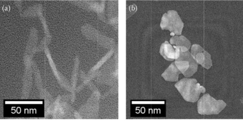
2: High-angle an 2 (b).
ose of QWs gr latter. The con ng the number ntum dots are c n a way simila
al.17. Magnetic
e effects of sp ects of excha n and the dime the component carrier wave fu roperties, such
s used in this stu
Sample 1 2 3 this paper, sum
synthesizing osition (c-ALD (sample 1, sam ce was coated otal thickness erostructures u agnetic sample ions and those
nnular dark-field rown by conve nfinement in th r of monolaye controlled by a ar to that used f c ions (in our
p-d exchange ange interactio ensions (confin t layers or (b) t functions with as PL circular
udy, the values i
mmarized in ta the NPL core D). In this work mple 3) or 3 ML with 1 ML of of 2 MLs wa used in this w es 1 and 2. The of the carriers d transmission e ntional epitaxi he z-direction in ers in each pla
adjusting their for colloidal qu
case, mangane interactions b ons can be ta nement and late the deposition the magnetic r polarization an in parentheses in Com CdSe (5) / Cd CdSe (3) / Cd CdSe ( able 1, were fa es and envelop k, core/shell N L (sample 2) se shell material ( s deposited (1 work is shown e latter were stu
.
electron microsc
ial methods and n NPLs allows atelet; this is an
size16. Nanopl
uantum dots; d ese) can be int etween the sp ailored throug eral). Wave fun
of one or more regions can be nd Zeeman spl
ndicate the numb
mposition dMnS (2) / CdS dMnS (2) / CdS (5) / CdS (2) fabricated acco
ping this core PL structures w eed CdSe cores
(either Cd0.985M
ML on each Figure 1. Non udied for the in
copy (HAADF-T
d therefore the s for the tailori nalogous to th latelets are syn details of the sy
troduced into t pins of the car gh the precise nction engineer e magnetic lay e controlled so litting. ber of monolaye S (2) S (2) ording to the p e with success were prepared s. During the c Mn0.015S or Cd of the top an n-magnetic sam nvestigation of TEM) images of e former exhibi ing of photon e he way that the nthesized colloi
ynthesis of the the layers of o rriers and thos e control of b
ring is achieve ers. Through s o that the NPLs
ers along the z-a
procedure desc sive shell laye by performing -ALD depositi S); as a result, nd bottom surf mple 3 was u f exchange inte f sample 1 (a), a it similar emission e optical idally by ese NPLs our II-VI se of the both the ed by: (a) structural s exhibit axis ribed by ers using g c-ALD ion, each for each faces). A used as a eractions and
2.00 2.0!5 2.10 2. Energy (eV) 15 2.20 I. 2.25 2.30 700 600 500 400 300 200 (a) 100 (b) 1.95 High-angle a are shown in rectangular s of sample 2, concentration spectroscopy 2.2 Experim For the PL a laser emitting geometry in w σ+ (left circu and linear an Figure 3 Gaussian and (ii), (ii) also In the upper p spectrum has functions cen energy (ii)) f same conditi This spectrum (iii) at 2.233 subband17. W comparison o heavy hole s transitions. annular dark-fi n panels of (a) shapes with ave
on the other ha n of the mag y (EDS) measur mental Meth and magneto-P g at 405 nm w which the appl ularly polarized nalyzer placed b
3: (a) The zero-f n functions that respectively. (b marked, the hig
panel of figure s a pronounced ntered at 2.036 feature. To pro ons. In figure m has two dist 3 eV; this featu We note that of panels (a) a ubband and PL ield transmissio ) and (b) of fig erage lateral di and, are difficu gnetic shell la rements, assum ods PL measuremen ith a maximum lied magnetic f d) and σ– (right
before the spec
field PL spectra represent a low b) The correspon ghest energy tran
e 3 we show th d asymmetry o 6 meV and 2.0 obe the origin
3b we plot the tinct features: f ure has been i PL feature (i and (b) in figur L feature (i), h on electron mi gure 2. The 5 imensions of 5 ult to determin ayers in samp ming uniform m nts, the NPLs m power densit field is parallel t circularly pol ctrometer entra
3.
of the magnetic w-energy (green nding derivative nsmission feature e zero-field PL on the low-ene 077 meV 18. W of these featu e spectral deriv feature (ii) at 2 identified as th i) has no corr re 3, we attribu having no corre icroscopy (HA ML CdSe see 55 ± 6 nm × 10 e as they tend ples 1 and 2 manganese ion were excited u ty of 0.2 W/cm l to the directio larized) compo ance slit.RESULT
c sample is show line) and a highof the transmiss e (iii) is attribute
L spectrum from ergy side; for We use a gree ures, we have a vative of the tr 2.036 eV coinc he excitonic tr responding sig ute feature (ii) esponding feat
AADF-TEM) im ed NPLs used
0 ± 2 nm. The to fold and hav
was determi distribution w
using the linea m2. The experim
on of the emitte onents using a
TS
wn as grey poin h-energy (blue lin
sion data is show ed to recombinat m sample 1 (gr this reason, it en (blue) line t also recorded ansmitted inten cides with the c
ansition involv gnature in the ) to an exciton
ture in the tran
mages of magn as cores of sam dimensions of ve more irregu ned using en with each CdMn arly polarized ments were con ed light. The PL
combination o
ts, result of fitti ne) component a wn in magenta p tion involving lig
rey points) rec was fit to the to indicate the the transmissio nsity as a func corresponding ving the first c e transmission nic transition th nsmission spec netic samples mple 1 exhibit f the 3 ML Cd ular shapes. Ma nergy-dispersiv nS shell. output of a so nducted in the L was analyzed of a quarter-wa ng this data to t are indicated by points with featu
ght holes. orded at T = 10 e sum of two G e low-energy ( on spectrum u ction of photon PL feature and confinement li n spectrum. F hat involves th ctrum, to non-e 1 and 2, t regular dSe cores anganese ve X-ray olid state Faraday d into its ave plate two y (i) ures 0 K. The Gaussian i) (high-under the n energy. d feature ight hole From the he lowest excitonic
a (b) 1.90
r
1.95 E 2.00 :nergy (eV) .95 2 i E 00 2.0 Energy (eV) 2.05 )a 2.11 - 0.05 ouskt0.00 -0.05 -0.10 c -0.15.S - 0.05 R - 0.00 00410. -0.05 -0.10 - -0.15 o a ( ) 0.10 0.05 0.05 0.00 2.10 Figure 4 (black) p the uppe the resul In figure 4a ( K. Red poin circular polar PL compone asymmetric s which is nea exchange int has a maxim recombinatio Figure 5 red (blac In the up are the r The PL line the two circu4: PL spectra fro points indicate σ er panel, the app
lt of a fitting tha
(4b) we show t nts indicate the rization at a pa ent. The spect shape of the PL ar zero at
zero-teraction betwe mum that coin on occurs in the
5: PL spectra fro ck) points indica pper panel, the a result of a fitting asymmetry is ularly polarized om magnetic sam σ+(σ-) circularly plied magnetic fi at uses two Gaus
the two circula e σ+ (LCP) PL
articular photo tral dependenc L emission per -field, becomes een the spins o ncides with th e vicinity of th
om non-magnetic ate σ+(σ-) circula
applied magnetic g that uses two G
also observed d PL compone mple 1 using an polarized PL co eld is 0 T and in sian functions to arly polarized P L component, w n energy is giv ce of the calc rsists in the pr s positive as th of the carriers he intensity m e manganese io c sample 3 using arly polarized PL c field is 0 T and Gaussian function in the non-ma ents at B = 0 T excitation wave omponents. The n the lower pane o the asymmetric
PL component while the blac ven by P = (I+ culated circula resence of an a he applied mag and those of th maximum of fe ons located in g an excitation w L components. T d in the lower pa ns to the asymm agnetic sample T (B = 7 T) rec elength of 405 nm cyan line is the l it is 7 T. The g c PL spectra. ts from sample k points denot -I-)/(I++I-) whe ar polarization applied magnet gnetic field is he Mn2+ ions19
eature (i) whic the CdMnS sh
wavelength of 40 The cyan line is t anel it is 7 T. Th metric PL spectra 3 as shown in corded at 7 K. m at a temperatu calculated circu green and blue li
e 1 at B = 0 T ( te the σ- (RCP
ere I+(I-) is the
n is shown as tic field. The c increased, indi 9. The polariza ch indicates th hells. 05 nm at a tempe the calculated ci he green and blu
.
n figure 5. In f Red points ind
ure of 7 K. The ular polarization nes in panel (a)
(B = 7 T) recor P) PL compon
intensity of th s the cyan lin circular polariz icating the pre ation peak in f hat the corres
erature of 7 K. T ircular polarizati ue lines in panel figure 5a (5b) w dicate the σ+ (L red . In are rded at 7 nent. The he σ+ (σ-) nes. The zation P, esence of figure 4b sponding The ion. (a) we show LCP) PL
0.20 0.15 0.10 0.05 0.00 -0.05 -0.10 -0.15
s=
o00
1 2 1.5 1.0 0.5 i 0.0 -1.oH
.5 -2.0 A04
--2.5 O 1 ,6 6, A AA A I_ 2'
3 magnetic field A A0 0 0
.
. . . . I
0Q..'
3 4 magnetic field (T'
1 5 (T) AA L A A A A M E r) component, emission from Figure 6 the mag In figure 6 t components, squares) and polarization CdMnS shell vanish by ap magnetizatio the polarizati The circular of the circula Figure 7 magenta The origin o distribution o imbalance is is defined as dependence o defined abov lower energy is true for th circular polarwhile the blac m sample 3 is n
6: Circular polar enta squares; sam
the net PL cir is plotted as a d 2 (cyan diam saturation valu l17. The polariz pproximately n we conclude ion for non-ma polarization of ar polarization 7: Zeeman splitti a squares; sampl of the PL circ of the ±1/2 elec
due to the ind ΔEZ = E+ – E -of ΔEZ in figu ve, is compatib y than the σ- co e non-magneti rization (P < 0 ck points deno negative; furth rization of PL pl mple 2 is indicat rcular polarizat a function of ap monds), P initia ue is larger th zation saturatio 25 K. Since e that the CdM agnetic sample f sample 3 is ne for sample 3 is ing of PL plotted e 2 is indicated b cular polarizati ctrons and the dividual Zeema
- where E+(E-)
ure 7 is similar ble with the sig omponent resul ic sample 3 wh ). ote the σ- (RC hermore, unlike otted as a functi ted by cyan diam
tion, determin pplied magneti ally increases w han that of sam on values of b
the circular p MnS shells exhi
e 3 (yellow tri egative and ha s due to the int
d as a function o by cyan diamond ion in magnet ±3/2 holes am an splitting in th is the “center-r to the depend gn of the pola lting in I+ > I
-here the σ- com
CP) PL compo e sample 1, it is
ion of magnetic monds; and samp
ned by spectral c field at a tem with field and mple 1 due to both samples 1 polarization fo bit Brillouin p angles) is disti as a nearly linea trinsic conducti of magnetic field ds; and sample 3 tic samples 1 mong the condu he conduction -of-mass” ener dence of P on B arization; for m and therefore mponent has a
onent. The ove s spectrally fea field at T = 7 K ple 3 is indicated lly integrating mperature of 7 saturates befo increased car and 2 decreas ollows the sam
aramagnetism1
inctly different ar dependence ion and valenc
d at T = 7 K. Da 3 is indicated by
and 2 is due uction and valen
and valence b rgy of the σ+(σ B shown in fig magnetic sampl positive circul lower energy erall circular p atureless.
K. Data for samp d by yellow trian
the intensitie K. For magnet ore 4 T. In the rrier wave func se dramatically me dependence 19. The magnet t from that of on magnetic f ce band g-facto
ata for sample 1 y yellow triangles
to the differe nce band spin ands. The net Z
σ-) PL compone
gure 6. The alg les 1 and 2, th lar polarization and thus I- > I polarization of le 1 is indicated ngles. s of the σ+ an tic samples 1 ( e data of samp ction overlap y with increasin e on B and T tic field depen
the magnetic field. The nega ors of CdSe20. is indicated by s. ence in the po states. This po Zeeman splitti ent. The magne
gebraic sign o he σ+ compone n (P > 0). The I+ resulting in f the PL d by nd σ- PL (magenta le 2, the with the ng T and T as the dence of samples. ative sign the opulation opulation ng, ΔEZ, etic field f ΔEZ as ent has a opposite negative
à 2.6 2.4 2.2 2.0 1.8
i
(a) r ONo*. 50 terI.
too 150 nperatu re (K) shell (i) shell 0.9 0.6J(
}
_+ -1 200 0.00V
(b) b r 0.02 0.04 0.06 inverse tempera! shéII ì 0.08 0.10 ture (K-1) Figure 8 The val tempera dashed l The depende interactions b PL features temperatures sharply with Eloc/kBT we process of tra presence of a equal to 4.2 m Figure 9 represen light gre the gree Based on th associated w hand involve This is strong 2 in the prese of holes and8: (a) The evolut lue of ln(Iii/Ii) ature regions are
line. ence of P and Δ between the ca identified in f s between 10 K increasing tem extract values ansition (i). Fo a band of close meV. 9: A diagram of nts energy and th ey lines indicate
n and blue arrow
he results of f with PL feature es recombinatio gly supported b ence of an exte d the spins of
tion of the ratio I is plotted versu identified and l
ΔEZ on magne
arrier spins and figure 3 is plo K and 90 K; ho mperature. In fi of Eloc, the lo
or the low temp ely spaced ener
the recombinati he horizontal ax es the thickness o ws marked (i) an
figure 8, we c s (i) and (ii). A on of delocaliz by the large po ernally applied Mn2+ ions is Iii/Ii as a functio us 1/T; here, Ii linear fits to the
etic field and te d those of the M
otted as a fun owever, for the
igure 8b we pl ocalization ene perature region rgy levels. In c
ion scheme of o xis, the position of single monol nd (ii) correspond construct a mo As mentioned zed electrons w ositive circular d magnetic fiel stronger (by a on of temperatur and Iii represen e high (low) tem
emperature for Mn2+ ions in th nction of temp temperature re ot the ln[Iii/Ii] ergy associated n (10 K ≤ T ≤ 9 contrast, Eloc in our core/multi-sh along the z (ver ayers. The two p ding to the corre
odel of the ba earlier, feature with hole states polarization as ld. Given the f a factor of 5) re for sample 1 i nt the respectiv mperature data ar r samples 1 an he CdMnS shel perature in figu egion between as a function o d with the car 90 K), the valu n the high-temp hell nanoplatelet rtical) dimension proposed recom esponding PL fea and structure e (ii) is exciton localized at th ssociated with fact that the ex than the corre
is indicated by th ve fitted PL pea re indicated by t
nd 2 shows the lls. The intensi ure 8a. This r n 90 K and 200 of 1/T; using th rriers involved ue of Eloc is ver perature region heterostructure n. The spacing b mbination channe atures identified
and the recom nic in nature; f he CdSe/CdMn feature (i) in m change interac esponding e-M he black points. ak intensities. T the cyan (magen
e presence of e ity ratio Iii/Ii of ratio changes 0 K, this ratio i he equation ln[ d in the recom ry small, indica n (90 K ≤ T ≤ 2 s. The vertical a between the grid els are indicated
in figure 3. mbination mec feature (i) on t nS core/shell in magnetic sampl ction between t Mn2+ interactio (b) Two nta) exchange f the two little for increases [Iii/Ii] = -mbination ating the 200 K) is axis d of d by chanisms the other nterfaces. les 1 and the spins n 19, we
o 5 o 2. 0.5 0.0 560 57 O IIILCIIILy tKIL/bi IJ P O O O Intensity (norm 70 580 59( wave) 0 1.95 2.00 2.05 2.10 Energy (eV) 0.6 0.9 1.2 Time (ns) I 2.15 ) 300 200 100 NNE
0
1.5 0.0 620 630 I Ê1.0 -ó x 168 c T0.5 . c 0 95 2.00 Eni 0.3 0.6 0.9 Time (ns; I. . 2.05 2.10 ergy (eV) 1.2 1.5 conclude tha magnetic ion discussed abo blue region i interfaces. Figure 1 the horiz the arriv To determine spectroscopy time slice (δ magnetic) sa energy in eV points) and 3 of the PL. Figure 1 magneti using do the inset spectra indicate The two PL shown in fig processes, i. at the localized ns and that tho ove in connect is the variation10: The intensity zontal axis corre val of the excitat
e the origin of y and in figure
δt = 10 ps), th
ample are show V and the vertic 3.5 ns (green p
11: The temporal c sample is sho otted green and ts represent time have been norm the magnificatio emission comp gure 9. An ana e., with no in d carriers invol ose carriers mu tion to figure 8 n of the locali y of the PL is re esponds to wave ion pulse. f these two PL 10 we show a he spectra are wn in the inset
cal is the norm oints). We not
l evolution of th own in panel (b) dashed blue line e slices of the tr malized and dark on factor for the
ponents labele alysis using a nter-channel e
lved in the rec ust be holes. T 8b. A possible ized holes stat
epresented by th elength in nm an L features, we 2D time-wave fit to a Gaus t of figure 11a malized intensit te that these trP he PL intensity fr ) using black po es, respectively. rPL spectra at Δ k count-correcte spectra at Δt = 3
d (i) and (ii) in bi-exponential nergy transfer combination pr The localization source of the tes energy in he color of this s nd the vertical ax studied the re elength map of ssian function; a (figure 11b). ty. The spectra PL spectra do
rom the magneti oints. The calcu The sum of the Δt = 0 ns (blue po ed so as to have 3.5 ns. n figure 3 corr l decay functio r. Instead, we rocess of featu n energy, Eloc, localized state the xy-plane o streak image, wh xis corresponds t ecombination d f the PL intensi examples of In these inset a shown as ins not exhibit the
ic sample is show ulated intensities
se intensities is oints) and at Δt = e the same peak
respond to the on to fit the P constructed a
ure (i) must be of the holes i s band shown of the nanopla
hich is mapped i to the time delay
dynamics in o ity for the mag these slices fo s, the horizont ets correspond e same degree wn in panel (a) a of features (i) indicated by red = 3.5 ns (green p k intensity, and two distinct re PL spectra assu a rate equatio e in the vicinit is equal to 4.2 in figure 9 as atelets at the c in two dimensio y as measured fr ur samples us gnetic sample. F for the magnet
tal axis corresp d to times of 0
of asymmetry
and that of the n and (ii) are sho d lines. The data points). These in the green numb
ecombination c umes two inde on-based mode ty of the meV as the light ore/shell ons; rom ing trPL For each tic (non-ponds to ns (blue as those on-own a of nset bers channels ependent el which
V CB 'í'_ \ dN; (t) dt
---(t) dt Nil (t) = CAN11 (-ßi-ßi
Nil (t) =R__,
(t) Nil (t) + C si N11 (t) ,811 e + Cf3iiNii incorporated assumptions: carriers; ther associated w high-energy because the e experiment w excitonic, is channel (ii) a Figure 1 excitatio Based on the Here, Ni(t) is associated w and C is a pa The analyticaUsing the ass
The value of solutions to t were constrai
a coupling of : First, the tim refore, we trea with excitation, channel (ii) to energy differen was conducted initially popul as indicated in 12: Schematic di on from the excit
ese assumption
s the number o with channel (ii) arameter that de al solutions to t sumption that t f Nii(0) was set the experiment ined to be with
f the two proc me resolution at the excitatio it is substanti the low-energy nce of those tw d. And third, ated and chann figure 13.
iagram of the re tonic channel (ii
s, we construct
of carrier pairs ), βi is the lifet
escribes the co this model are
the state associ
t to the PL inte tally obtained hin the interval
cesses. To sim of the streak on of electron-ially shorter th y channel (i); t wo processes is the result of nel (i) is empty
ecombination cha i) to the interface t the following at time t asso time associated upling between :
iated with chan
ensity at t = 0 a data. Values fo l [0,1].
mplify the solu measurements hole pairs to b han the resolut
transfer in the s much greater photo-excitati y at t = 0. The annels shown in e-related channe g system of cou ociated with ch d with channe n the two chan
nnel (i) is initia
and the remain or βi and βii we utions of these in this study be instantaneo tion. Second, e opposite direct r than kBT, giv ion is that pr e latter become n figure 4. In thi el (i) indicated by upled differenti hannel (i), Nii(t l (i), βii is the nnels. ally unpopulate ning parameter ere constrained rate equation y exceeds the us. While ther energy transfer tion, i.e., from en the low tem imarily only c es populated vi
s figure, we incl y the yellow arro
ial equations:
t) is the numbe
lifetime associ
ed, the solution
rs: βi, βii and C d to be non-ne ns, make the fo excitation tim re is a finite ti r occurs only f (i) to (ii), is ne mperature at wh channel (ii), w ia energy trans
lude the transfer ow.
er of excitons iated with chan
ns simplify to:
C were used to
gative and valu ollowing me of the imescale from the egligible hich this which is sfer from r of (1) (2) at time t nnel (ii), (3) (4) (5) (6) fit these ues of C
The results of the fit for the magnetic (non-magnetic) sample are summarized in figure 11. In the main panels of figure 11a and 11b, we plot the following: calculated PL intensity of channel (i) using dotted green lines; calculated PL intensity of channel (ii) using dashed blue lines; calculated PL intensity of both channels using red lines (sum of green and blue lines); and the experimental PL intensities integrated over all recorded wavelengths using black points.
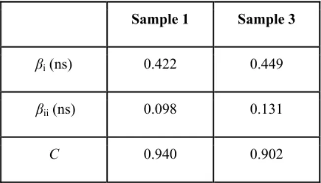
The resulting fit parameters are summarized in table 2.
Table 2: Fit parameters of the time-resolved PL intensity using the solutions of our rate equation model.
Sample 1 Sample 3
βi (ns) 0.422 0.449
βii (ns) 0.098 0.131
C 0.940 0.902
Our approach is to fit the solutions to the spectrally integrated intensity over all recorded wavelengths as shown in figure 11a and figure 11b. The difference in the values obtained for βi and βii is compatible with the fact that channel (ii) is
excitonic while channel (i) is due to recombination between free electrons with localized holes. We note that the values of the extracted lifetimes (in particular that of the slow process, (i)), while sensitive to the underlying assumptions, always result in two distinct timescales. Of the lifetimes associated with these processes the lower-energy process is significantly slower than that of the high-energy process. We identify the parameters βi and βii listed in table 2 as the
lifetimes associated with the respective channels.
4. CONCLUSIONS
We have studied the magneto photoluminescence of solution-grown nanoplatelets that consist of CdSe cores, followed by CdMnS shells and are terminated with CdS shells. In the presence of an externally applied magnetic field, the net PL emission becomes predominantly left circularly polarized (σ+) indicating the presence of exchange interaction between
the spins of the carriers and those of the Mn2+ ions. The sign of the Zeeman splitting is compatible with the circular
polarization of the PL emission, i.e., E+ < E-, where E+ (E-) is the energy associated with the recombination of -1/2 (+1/2)
electrons with +3/2 (-3/2) holes. Both the circular polarization and the Zeeman splitting have a Brillouin-like dependence on magnetic field and temperature. The photoluminescence emission is asymmetric and can be decomposed into two Gaussian features. The circular polarization maximum coincides with the intensity peak of the low-energy feature. Using the Mn2+ ions as a marker, we identified this low-energy feature as due to recombination of delocalized electrons with
holes localized at the CdSe/CdMnS interface. The high-energy feature is excitonic in nature and involves recombination of delocalized electrons with holes confined in the CdSe core. The presence of two distinct lifetimes, βi and βii,
determined from the analysis of trPL experimental results further support this suggested model.
ACKNOWLEDGEMENTS
The authors would like to thank EU-FP7 Nanophotonics4Energy NoE, and TUBITAK EEEAG 109E002, 109E004, 110E010, 110E217, and 112E183, and NRF-RF-2009-09, NRF-CRP-6-2010-02, and A*STAR of Singapore for the financial support. H.V.D. acknowledges support from ESF-EURYI and TUBA-GEBIP. Work at the University at Buffalo was supported by NSF DMR 1305770.
REFERENCES
[1] A. P. Alivisatos, “Perspectives on the Physical Chemistry of Semiconductor Nanocrystals,” The Journal of Physical Chemistry, 100(31), 13226-13239 (1996).
[2] R. Dingle, [Confined carrier quantum states in ultrathin semiconductor heterostructures] Springer Berlin Heidelberg, (1975).
[3] R. D. Dupuis, P. D. Dapkus, N. Holonyak et al., “Room‐temperature laser operation of quantum‐well Ga(1−x)AlxAs‐GaAs laser diodes grown by metalorganic chemical vapor deposition,” Applied Physics Letters, 32(5), 295-297 (1978).
[4] S. Ithurria, and B. Dubertret, “Quasi 2D Colloidal CdSe Platelets with Thicknesses Controlled at the Atomic Level,” Journal of the American Chemical Society, 130(49), 16504-16505 (2008).
[5] S. Ithurria, M. D. Tessier, B. Mahler et al., “Colloidal nanoplatelets with two-dimensional electronic structure,” Nature Materials, 10(12), 936-941 (2011).
[6] J. Joo, J. S. Son, S. G. Kwon et al., “Low-Temperature Solution-Phase Synthesis of Quantum Well Structured CdSe Nanoribbons,” Journal of the American Chemical Society, 128(17), 5632-5633 (2006).
[7] Z. Li, H. Qin, D. Guzun et al., “Uniform thickness and colloidal-stable CdS quantum disks with tunable thickness: Synthesis and properties,” Nano Research, 5(5), 337-351 (2012).
[8] C. Schliehe, B. H. Juarez, M. Pelletier et al., “Ultrathin PbS Sheets by Two-Dimensional Oriented Attachment,” Science, 329(5991), 550-553 (2010).
[9] S. Ithurria, and D. V. Talapin, “Colloidal Atomic Layer Deposition (c-ALD) using Self-Limiting Reactions at Nanocrystal Surface Coupled to Phase Transfer between Polar and Nonpolar Media,” Journal of the American Chemical Society, 134(45), 18585-18590 (2012).
[10] Y. Kelestemur, M. Olutas, S. Delikanli et al., “Type-II Colloidal Quantum Wells: CdSe/CdTe Core/Crown Heteronanoplatelets,” The Journal of Physical Chemistry C, 119(4), 2177-2185 (2015).
[11] B. Mahler, B. Nadal, C. Bouet et al., “Core/Shell Colloidal Semiconductor Nanoplatelets,” Journal of the American Chemical Society, 134(45), 18591-18598 (2012).
[12] M. D. Tessier, P. Spinicelli, D. Dupont et al., “Efficient Exciton Concentrators Built from Colloidal Core/Crown CdSe/CdS Semiconductor Nanoplatelets,” Nano Letters, 14(1), 207-213 (2014).
[13] M. D. Tessier, B. Mahler, B. Nadal et al., “Spectroscopy of Colloidal Semiconductor Core/Shell Nanoplatelets with High Quantum Yield,” Nano Letters, 13(7), 3321-3328 (2013).
[14] S. Delikanli, B. Guzelturk, P. L. Hernandez-Martinez et al., “Continuously Tunable Emission in Inverted Type-I CdS/CdSe Core/Crown Semiconductor Nanoplatelets,” Advanced Functional Materials, 25(27), 4282-4289 (2015).
[15] B. Guzelturk, M. Olutas, S. Delikanli et al., “Nonradiative energy transfer in colloidal CdSe nanoplatelet films,” Nanoscale, 7, 2545-2551 (2015).
[16] C. B. Murray, D. J. Norris, and M. G. Bawendi, “Synthesis and characterization of nearly monodisperse CdE (E = sulfur, selenium, tellurium) semiconductor nanocrystallites,” Journal of the American Chemical Society, 115(19), 8706-8715 (1993).
[17] S. Delikanli, M. Z. Akgul, J. R. Murphy et al., “Mn2+-Doped CdSe/CdS Core/Multishell Colloidal Quantum Wells Enabling Tunable Carrier-Dopant Exchange Interactions,” Acs Nano, 0(ja), null-null (2015).
[18] J. R. Murphy, S. Delikanli, T. Scrace et al., “Time-resolved photoluminescence study of CdSe/CdMnS/CdS core/multi-shell nanoplatelets,” Applied Physics Letters, 108(24), 242406 (2016).
[19] J. K. Furdyna, “Diluted magnetic semiconductors,” Journal of Applied Physics, 64(4), R29-R64 (1988).
[20] G. Long, B. Barman, S. Delikanli et al., “Carrier-dopant exchange interactions in Mn-doped PbS colloidal quantum dots,” Applied Physics Letters, 101(6), 062410-062410 (2012).