1O.1109/ULTSYM.2012.0248
Electrically Unbiased Driven Airborne Capacitive
Micromachined Ultrasonic Transducer Design
Asli Unlugedik, Abdullah Atalar, Coskun Kocabas*, H. Kagan Oguz and Hayrettin Koymen
Bilkent University, Electrical and Electronics Engineering Department, *Physics Department, Ankara, Turkey
e-mail: [email protected]
Abstract-
We present a design method for airborne capacitive micromachined ultrasonic transducers (CMVT). We use an equivalent lumped element circuit to model both electrical and mechanical properties of CMUT and analyze it in frequency domain using harmonic balance approach. We use this method to design CMUTs for large transmitted power generation at low drive voltage amplitude. We determine the dimensions of an airborne CMUT using the proposed method that works at30
kHz with 5 rum radius,240
11m membranethickness and
11.8
11m effective gap height. The CMUT is designed such that an atmospheric depression of70%
of effective gap height is maintained.I. INTRODUCTION
Airborne CMUTs offer high efficiency and wider bandwidth due to their low characteristic impedance. This property makes CMUT advantageous over the other transduction mechanisms
[1].
CMUT design has several challenges. CMUTs are designed and designs are tested using finite element method (FEM). This process is computationally very intensive. Moreover, the design space is prohibitively large due to large number of physical design variables.In this work, we provide a systematic design technique to optimize CMUTs with respect to a performance parameter using a computationally feasible method. We use a circuit model of the CMUT to model both mechanical and electrical domains. We perform a frequency domain analysis using harmonic balance (HE) approach in our design and optimization. We demonstrate our method by designing a CMUT structure for power transmission at
30
kHz.II. METHOD
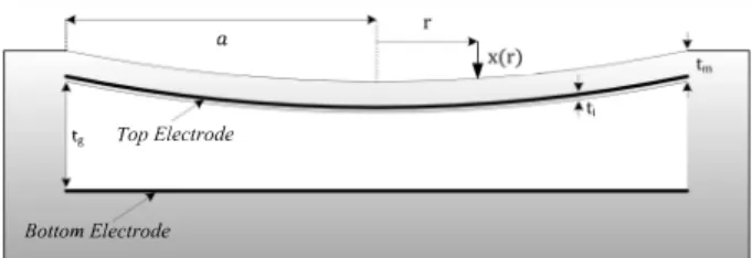
A cross sectional view of a circular airborne CMUT and its important parameters are shown in Figure
1,
wherea
is the diameter of the CMUT,tge
is the effective gap height,t;
is the insulating layer thickness, andtm
is the membrane thickness, F is the total force exerted on the membrane.978-1-4673-4562-0/12/$31.00 m012 IEEE 991
.�I--->
a
x(rl. __ _
___ -'--_.---L
-I�-
t... Top Electrode,
Bottom Electrode
Fig.
1.
Cross sectional view of circular airborne CMUT. CMUTs have two electrodes as shown in Figure1.
The top electrode is in the movable plate and the bottom electrode is placed on the substrate. The downward movement of top plate is limited with gap height. Driving this capacitive structure with an electrical input signal moves the top plate and generates acoustic waves. Power and the other important performance parameters of the generated waves such as center frequency and bandwidth depends on the device geometry.We use the lumped element model
[2]
of CMUT, shown in Figure2.
The model consists of an electrical input port, and a mechanical output port. Mechanical section of the lumped model is terminated by an acoustic port loaded by radiation impedance. The radiation impedance in the air is low and therefore the mechanical side has narrow bandwidth characteristics.Fig.
2.
Equivalent circuit model of CMUT.CMUT's mechanical section elements are linear. They remain unchanged for high power operation since the membrane displacement is very limited. Therefore, we have essentially a linear LC section.
Lm
represents the mass and c'n represents the compliance of CMUT membrane[2].
The radiation impedance is also linear. Hence the only nonlinear component in the mechanical section is the generated force[2]
given in equation
(1)
(1)
where C
o
=co
7fa
2/tg is the input capacitance of CMUT,co
is thefree space permittivity, tge = tg+t/f.r is the effective gap height,
V(t) is the applied input voltage. The mechanical section is a narrowband system centered around the resonance frequency of the mechanical section. As far as the mechanical section is concerned, the only significant displacement components are at DC and at
w,
when it is in the vicinity of the resonance frequency of mechanical section. On the other hand, many harmonics are generated by the controlled force term. The DC component determines the total charge on c'm which corresponds to a static plate deflection. Hence we can assume,Xp(t) '" X DC + xac cos(ax)
()
tanh-,(-Fu
)g u
=.Ju
g'(u)
=_1
(
_1
__ g (U»
)
2u 1
-
u
(2)
(3)
(4)
We employ HE to analyze the circuit given in Fig.
2.
We expandedg'(u)
in terms of Fourier series to obtain (5).(5)
where, Gil'S are the Fourier coefficients. Vet) is given by
Vet) =Vm
cos(
�
+B)
(6)1
V2[1
]
X -� G +-G 3 V2 02
'
cos(2B)
+F: bll =� t r ge where, F bll =1ltl2p 0 Cpm t ge(8)
(9)and Vr is the collapse voltage of a CMUT in vacuum
[1], Po
is the atmospheric pressure, XDC is the DC component of the center displacement, CPm is the compliance in the peak velocity circuit. In Eq.(8),
the fIrst term corresponds to the DC part of generated force, the second term corresponds to atmospheric pressure and the last term corresponds to restoring force of the spring.We use a numerical method to solve Eq.
(8).
This enables us to generate a dependency between xa!tge, XDC/tge V mlVr ande. Note that the number of unknowns is greater than the number of equations. Therefore, we obtain a large solution set. We narrow our solution set by imposing the design constraints.
We balance the
w
term to fInd the resonance frequency in order to maximize power transmission. This is given byIV2
[
1
]
-� G, + Go
cos(2
B) + -G2 cos(2
B) =3 Vr
2
Xac
(1-OJ2LIIlCm -OJCIIlXr)
t ge
(10)
where, Xac is the center displacement's AC part, Xr is the susceptance of the radiation impedance that depends on frequency. Note that, there is a nonlinear dependency between V 2
V2(t) = _
m
_[
l +COS(OX
+2B)]
2
(7)
voltage amplitude and frequency.where, e is the phase of the input signal.
The generated force is proportional to the square of the input signal. In order to have a fundamental component at
w
at the mechanical part, we must drive the electrical section atwl2.
Conventionally, the membrane depression is set by using the DC term of the input signal. We avoid using the DC bias component of the input signal by exploiting the depression due to atmospheric pressure. The depression level depends on atmospheric pressure and DC tone generated by the force.
A. Harmonic Balance Approach
When
w
is in the vicinity of the resonance frequency, the signal at the output acoustic port is large. We employ HB technique to determine DC and the fundamental component in the mechanical section. Initially, the static force balance can be put into the following form992
We reformulate Eq.
(10)
to show a/tm dependency by substituting the equations given in(11),
2
OJr
1
(11)
We use the values of components
[2]
of peak velocity equivalent circuit(12)
(
13
) Hence we obtainwhere, and c 2 = 9
(
1-0.2)p
80Y, o (14) (15) (16) Now we can also findw/wr
anda/tm
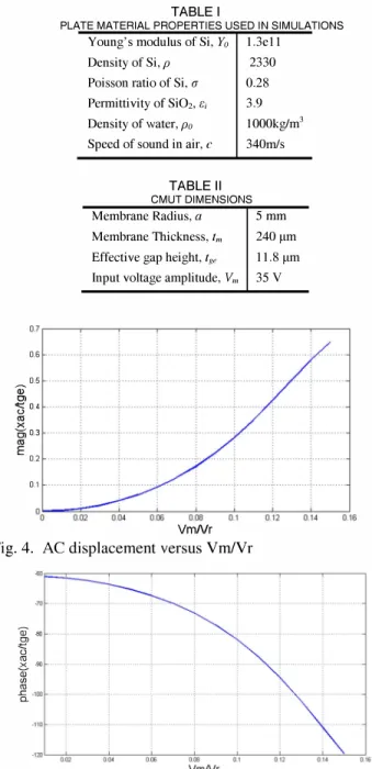
dependency. Table I lists the material properties used in the simulations.We selected
ka
as 3 to ensure that the real part of radiation impedance is near its maximum and Fbll=O.l to maximize the swing. Our goal in this example is to achieve maximum swing with the lowest input voltage level. We plotxa/tge
versus V"IVr as shown in Fig. 4. We observe that the achievable peak displacement amplitude is very close to the gap height, 0.7 of effective gap height of the membrane. This corresponds to the maximum swing.We use sinusoidal input signal without any DC bias voltage. Applying a DC bias reduces membrane swing to 0.5 of
tge
[2], after this point membrane is collapsed. We overcome this limitation by avoiding a DC bias. It is desirable to find a point which ensures the maximum swing and a reasonable voltage level. The maximum membrane displacement is 0.7 oftge'
We would like to maximize membrane displacement for a low collapse voltage.Fig. 5 shows the phase of AC displacement of the membrane. The device resonates at V,,/V FO.l and yields a normalized membrane swing of 0.3 (Fig. 4), where VF18720V. Therefore, a drive voltage amplitude (V m) of l872V is required, which is not practical. This voltage can be significantly reduced for large Fbll.
A. Membrane with large static depression
One of the important parameters in CMUT design is the external pressure. In the above example, the initial static depression of membrane due to the atmospheric pressure is set to Fbll =0.1. The membrane displacement almost reaches the effective gap height with this static depression. However, this results in a high collapse voltage [2]. Increasing Fbll is advantageous since it reduces the collapse voltage. However, we cannot depress the membrane indefinitely as over depression may result in permanent collapse. We select device parameters to maintain the desired depression for a given atmospheric pressure level.
993
TABLE I
PLATE MATERIAL PROPERTIES USED IN SIMULATIONS Young's modulus of Si, Yo l.3ell
Density of Si, p 2330 Poisson ratio of Si, (J 0.28 Permittivity of Si02, Ii; 3.9 Density of water, po
Speed of sound in air, c
TABLE II 1000kglm3 340mls CMUT DIMENSIONS Membrane Radius, a 5 mm Membrane Thickness, 1m 240 !lm Effective gap height, Ig, 11.8 !lm Input voltage amplitude, Vm 35 Y
O.7 r--"--�---'--�--�--'--�---' 0.6 0.5 Q) Cl '5 0.4 '" >< CiO.3 '" E 0.2 0.1 °0���=-�-��-0�.re�����-�-�0.·16 YmNr
Fig. 4. AC displacement versus VrnlVr
.lOc · ·;· · · (j) .oo CD '5 '" x .", ill (/) '" -a. .1oof- ·;· · · . . · · · ·;· · · ·;·
Fig. 5. Phase of AC displacement versus Vm/Vr
We explain this through an example and show that Vr can be reduced for a high initial static depression. We design a CMUT with 30 kHz operation frequency and use an initial static depression due to atmospheric pressure of Fbn=0.7. We choose this value in order to achieve the highest depression with small Vr while avoiding the collapse of the membrane. The other input parameters used in this example are ka=3 and
a/tm
=22.5Using the circuit model given in [2, 3], we obtain the important dimensions for maximum output power and collapse voltage value of a CMUT that works near its resonance frequency. Fig. 6 and Fig. 7 show the normalized swing and phase of membrane with respect to Vn/Vr. Fig. 7 reveals that the device resonates at V m/Vr=0.035 and yields a normalized membrane swing of 0.13 (Fig. 6). Moreover,
a
is found to be 5 mm,tm
is 240f..lm,tge
is 1 1. 8 f..lm , and Vr is approximately 35V.The designed CMUT has Vr=1000 V. Hence, the required driving voltage is 35 V. O.J5,--�----'---,---.-�-�----r----.---�---, 0.3 0.25 0.05
Fig. 6. Ac displacement versus VrnlVr
4>"100 '" '5 '"
�-1�
� 0.·140Fig. 7. Phase of ac displacement versus Vm/Vr III. FABRICATION
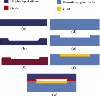
The fabrication process of the designed CMUT consists of
three steps. The fabrication steps are shown in Fig. 8. In the
first step, a silicon wafer with a thickness of 250 �m is etched by 11 �m using inductively coupled plasma (lCP) to obtain the required membrane thickness. We use an isotropic silicon etching procedure to avoid pillars due to photoresist residues.
In the second step, we prepare the bottom electrode on a borosilicate substrate. The borosilicate wafers are etched about 100 nm using reactive-ion-etching followed by evaporation of 100 nm gold to form the bottom electrode.
In the third step, the silicon membrane and the borosilicate substrate are bonded to each other. The bonding procedure is performed in Applied Microengineering Ltd., Oxfordshire,UK. We have not finished this step yet.
Required collapse voltage is a strong function of Fbn Increasing Fbll relaxes V m constraint (Section II-B). However,
large Fbll may result a permanent collapse. Selection of Fbn is limited by fabrication accuracy. For our process we choose Fbll=0.7.
994
•
Highly-doped siliconIII
Borosilicate glass wafer•
Oxide•
Gold -(b) (e)-
(c) (1) (g)Fig. 8. Fabrication steps: (a) conductive silicon wafer, (b) silicon etching for cavities, (c) thermal oxidation, (d) borosilicate glass wafer, (e) lithography and glass etching for bottom electrode, (f) Til Au evaporation, (g) anodic bonding.
IV. CONCLUSIONS
We used an analytic model for efficient airborne CMUT design. In solution the frequency components only at DC and
w are balanced, because the system is high-Q. A higher swing
is achieved with no DC bias voltage in input signal. Results show that atmospheric pressure helps reduce driving voltage level. Using the model, an airborne cMUT that works at 30
kHz is designed.
ACKNOWLEDGEMENT
This work is supported in part by Turkish Scientific and Research Council (TUBIT AK) under project grants I1OE2I6. Authors would like to thank ASELSAN for providing material resources. Work was performed in UNAM, NANOT AM and ARL, all at Bilkent University.
REFERENCES
[I] I. O. Wygant, et aI., "50-kHz capacitive micromachined ultrasonic transducers for generating highly directional sound with parametric arrays," in 2007 IEEE Ultrasonics Symposium, 2007, pp. 519-522. [2] Koymen, H., Atalar, A, Aydog;du, E, Kocaba�, C, Og;uz, H.K., Ol"um, S,
Ozgtirltik, A., Unltigedik, A., "An improved lumped element nonlinear circuit model for a circular CMUT cell," IEEE Trans. Ultrason. Ferroelectr. Freq. Control, vol. 59, no. 8, pp. l791-1799, August 2012. [3] H. K. Oguz, et aI., "Analysis of Mutual Acoustic Coupling in cMUT
Arrays Using an Accurate Lumped Element Nonlinear EquivalentCircuit Model in 2012 IEEE Ultrasonics Symposium, Dresden, October, 2012.