Inter-Numerology Interference Analysis for 5G and
Beyond
Abuu B. Kihero
∗, Muhammad Sohaib J. Solaija
∗, Ahmet Yazar
∗and H¨useyin Arslan
∗†∗
Department of Electrical and Electronics Engineering, Istanbul Medipol University, Istanbul, 34810 Turkey
†Department of Electrical Engineering, University of South Florida, Tampa, FL 33620 USA
Email: {abkihero, msolaija}@st.medipol.edu.tr,{ayazar, huseyinarslan}@medipol.edu.tr
Abstract—One of the defining characteristics of 5G is the flexibility it offers for supporting different services and com-munication scenarios. For this purpose, usage of multiple nu-merologies has been proposed by the 3rd Generation Partnership Project (3GPP). The flexibility provided by multi-numerology system comes at the cost of additional interference, known as inter-numerology interference (INI). This paper comprehensively explains the primary cause of INI, and then identifies and describes the factors affecting the amount of INI experienced by each numerology in the system. These factors include subcarrier spacing, number of used subcarriers, power offset, windowing operations and guard bands.
Index Terms—5G New Radio, inter-numerology interference, multi-numerology systems.
I. INTRODUCTION
5G is expected to act as a platform enabling wireless connectivity to all kinds of services. The different service classes defined for 5G include enhanced mobile broadband (eMBB), massive machine type communications (mMTC), and ultra-reliable and low latency communications (URLLC) [1]. These scenarios have their own specific demands causing 5G to have a wide range of requirements which dictates the need for a high degree of flexibility in the radio and network designs [2].
One of the steps taken towards achieving the required flex-ibility in 5G systems is the introduction of multi-numerology concept under the umbrella of 5G New Radio (5G-NR). The term numerology in 5G refers to a set of parameters like subcarrier spacing, symbol length and cyclic prefix in Orthog-onal Frequency Division Multiplexing (OFDM). The diverse requirements for the different service classes in 5G cannot be supported by the uniform time/frequency resource allocation provided by 4G Long Term Evolution (LTE). This renders the use of multiple numerologies imperative in providing the flexibility required for optimized individual services in 5G. Table I provides a summary of the properties of different NR numerologies as presented in [3] and [4]. Usage of multiple numerologies significantly affects the performance of the system. These effects include spectral efficiency, scheduling complexity, computational complexity, and signaling overhead [5]. Employing multiple numerologies also introduces non-orthogonality into the system, causing interference between users belonging to different numerologies.
Interference in multi-numerology systems, also called inter-numerology interference (INI) has garnered increasing
atten-TABLE I: Numerology structures for data channels in 5G [3]
∆f (kHz) TCP (µs) Slot Duration (ms) 15 4.76 1 30 2.38 0.5 60 1.19 | 4.17 0.25 120 0.6 0.125
tion in recent times. An INI model is presented in [6] which describes INI as a function of frequency response of the interfering subcarrier, frequency offset between the interfering and the victim subcarriers, and the overlap in transmitter and receiver windows of the interferer and victim, respectively. Though detailed, this model is limited to windowed-OFDM system. Similarly, [7] uses adaptive windowing to minimize the interference and [8] tries to optimize the guard band and time keeping in view the power offset and requirements of the users. While these works have shed some light on the phenomenon of INI, a study which accounts for and individually explains all the factors contributing to INI is still lacking. Such a study is imperative as it would enable the development of efficient interference cancellation techniques for multi-numerology systems in 5G and beyond. In this paper, we attempt to address the above mentioned gap in the present literature by contributing the following:
• An extensive discussion on synchronization and
orthog-onality issues of multi-numerology systems is provided.
• The factors that affect INI are identified and their effects are explained in light of simulation results.
• This work also presents research opportunities regarding interference in multi-numerology systems.
The rest of the paper is organized as follows: Section II describes the system model used in this study and the assumptions that form its basis. Section III discusses the effects of multiple numerologies from orthogonality and syn-chronization perspective. This is followed by highlighting the parameters that govern INI, accompanied by simulation results and intuitive interpretation of each of them in Section IV. Section V summarizes our findings and indicates the possible future direction of research.
II. SYSTEMMODEL ANDASSUMPTIONS
Multi-numerology is a key concept of the 5G-NR frame structure. Our system model considers two numerologies
N-po nt IFFT f1 Subcarr er Spac ng S/P X P 1 OFDM Symbol CP Add t on for Each
Symbol (N/2k)-po nt IFFT 2k x f1 Subcarr er Spac ng S/P Xj Pj 1 2 .... 2k CP Add t on for Each
Symbol 2kOFDM Symbols P/S P/S Transm tter Compos te S gnal CP Removal S/P CP Removal S/P N-po nt FFT f1 Subcarr er Spac ng (N/2k)-po nt FFT 2k x f1 Subcarr er Spac ng Rece ver To Detect on To Detect on
Fig. 1: Block diagram of the conventional multi-numerology implementation [9]
which is the base case for multi-numerology systems. It can be generalized to any number of numerologies by consider-ing one pair at a time. Each numerology block consists of multiple user equipments (UEs) which are non-overlapping in the frequency domain. It is assumed that the UEs have gone through a numerology selection process based upon the user and service requirements which may lead to different power levels amongst the users. This may be achieved by algorithms such as the one presented in [5]. In our model each numerology is assumed to cater to three users where the users of a particular numerology occupy equal bandwidth. The data generated consists of binary phase shift keying (BPSK) symbols. Since choice of modulation scheme is not our primary concern for the time being, we have limited ourselves to BPSK because of its simplicity. Fig. 1 shows the block diagram of the multi-numerology implementation used in this paper. Xi and Xj are complex modulated symbols for
users i and j of numerology-1 (N U M1) and
numerology-2 (N U M2), respectively. The users indices are defined as
i = 1, 2, ..., Q and j = 1, 2, ..., R, where Q and R are number of users scheduled in the corresponding numerologies. Pi and Pj are power ratios for ith and jth users in each
numerology. The first numerology employs subcarrier spacing ∆f1 and N-point inverse Fourier transform (IFFT) while the
second numerology’s subcarrier spacing and IFFT size are scaled by a factor of 2k and 1/2k respectively, where k is a positive integer. Similarly, the number of OFDM symbols for the second numerology is upscaled by 2k as compared to first numerology. The IFFT operation is followed by addition of cyclic prefix (CP) with a certain ratio, CPR, at the beginning
of each symbol. In this study, we have narrowed down our focus on the factors affecting INI without considering noise or a wireless channel. The receiver removes CP before taking N -point and N/2k-point Fast Fourier Transform (FFT) for
first and second numerology, respectively. We have employed Monte Carlo method to observe and analyze the interference statistics for each used subcarrier over 500 independent trials for each scenario discussed in following sections.
III. INTERNUMEROLOGYSYNCHRONIZATION AND
ORTHOGONALITY
Symbol lengths among numerologies tend to vary due to the usage of different subcarrier spacing (ScS) which in turn
makes the whole system unsynchronized in the time domain. Difficulty in achieving synchronization of OFDM symbols of different numerologies is one of the major drawbacks of multi-numerology systems. However, if ScS of one multi-numerology is integral multiple of the ScS of the other numerology, syn-chronization can be achieved over the so called least common multiplier (LCM) symbol duration [10]. For instance, if ScS of N U M1, ∆f1, and that of N U M2, ∆f2, are such that ∆f2
= 2k · ∆f1, then, 2k symbols of N U M2 can be perfectly
synchronized with 1 symbol of N U M1, i.e 2k·T2= T1, where
T is the symbol duration. In this case, T1 is the LCM symbol
duration. Synchronization over LCM symbol duration can be achieved in two ways:
By using individual CPs: This is the conventional way of creating a synchronous composite signal of N U M1 and
N U M2 in 5G where CPs are added to each symbols of each
numerology before the creation of the composite signal, as shown in Fig. 2(a). In this case, duration T of the synchronous symbols can be written as
T = T1+ T1CP = 2k· (T2+ T2CP). (1)
By using common CP: In this approach, multi symbols encap-sulated OFDM (MSE-OFDM) is adopted in the numerology with shorter symbol duration (i.e N U M2 in our case), which
allows one CP to be used for 2kconcatenated OFDM symbols
[11], [12]. CP size of N U M2, T 0CP
2 , is then determined from
the resultant length of the concatenated 2k symbols, which
makes T20CP = 2k· TCP
2 . In this case, a common CP can be
used for both numerologies as shown in [13]. The common CP of length TcCP = T1CP = T
0CP
2 , is appended after creation
of the composite signal of N U M1 and N U M2 as show in
Fig. 2(b). The duration T in this case is given by T = T1+ TcCP = 2
k· T
2+ TcCP. (2)
However, due to the adoption of MSE-OFDM in N U M2,
extra FFT and IFFT blocks are required at N U M2receiver to
facilitate proper equalization and data detection as discussed in [11] and [12].
To understand how INI affects multi-numerology signal synchronized by either of the above discussed approaches, let us first understand the coexistence of N U M1 and N U M2
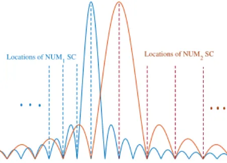
subcarriers at the transmitter side before creation of the composite signal. We observe from Fig. 3 that N U M1 causes
(a) Synchronization with individual CP
(b) Synchronization with common CP
Fig. 2: Synchronizing Symbols of N U M1 and N U M2 for k
= 1
no interference at any of the N U M2subcarriers, while N U M2
imparts some interference on one out of every two subcarriers of N U M1. Number of N U M1 subcarriers affected by INI
from N U M2 depends on the ratio ∆f1/∆f2 of the two
numerologies.
Locations of NUM1 SC Locations of NUM2 SC
Fig. 3: Multiplexed subcarriers of N U M1(∆f1= 15 kHz) and
N U M2 (∆f2 = 30 kHz) at the transmitter (before composite
signal) with guard band = ∆f1.
At the receiver, users of each numerology concentrate on capturing and decoding their own symbols from the composite signal depending on the numerology specification (Fig. 4). Common CP case: Fig. 4(a) summarizes what happens at N U M1 and N U M2 receivers when common CP is used for
synchronization. FFT window at N U M1 receiver captures a
full N U M1symbol from the composite signal as well as two
full symbols of N U M2 as shown in Fig. 4(a) (blue window).
The N -point FFT (corresponding to 2k∗(N/2k)-point FFT for
N U M2) at N U M1receiver does not disturb N U M2samples
present in the composite signal (i.e N U M2 subcarriers do
not lose their orthogonality due to FFT process at N U M1
receiver). Therefore N U M2 subcarriers do not create any
extra interference to N U M1 at the receiver. On the other
hand, when FFT window at N U M2 receiver captures one
symbol of N U M2 from the composite signal, it also captures
a “portion” of N U M1symbol (Fig. 4(a) (red window)). Thus,
the FFT operation at N U M2 receiver causes disturbance on
the N U M1samples contained in the composite signal (i.e loss
of orthogonality between subcarriers of N U M1 at N U M2
receiver), leading to interference from sidelobes of N U M1 to
each subcarrier of N U M2. The zero interference from N U M1
to each location of N U M2subcarriers (shown in Fig. 3) will
no longer be the case. Interference analysis at the receiver was done and error vector magnitude (EVM) of each subcarrier of N U M1 and N U M2 was observed (Fig. 5). From Fig.
5(a), for common CP case, we observe that one out of every two subcarriers of N U M1 has zero EVM. This shows that
interference on N U M1is the only one that was created at the
transmitter (Fig. 3) while all the subcarriers of N U M2 are
affected by INI even though they were interference-free at the transmitter.
(a) Common CP case
(b) Individual CP case
Fig. 4: Illustration of FFT-window at the receiver of each numerology (for k = 1)
Individual CP case: From Fig. 4(b), we observe that FFT window at the receiver of each numerology captures a portion of the symbol (not the full symbol) of the other numerology contained in the composite signal. Therefore FFT process at N U M1 receiver causes interference from N U M2 to all
subcarriers of N U M1, and FFT process at N U M2 receiver
causes interference from N U M1 to N U M2. This is revealed
by Fig. 5(b) where all subcarriers for each numerology are in error due to INI.
According to the above discussion, we can say that the common CP case renders the multi-numerology system par-tially orthogonal while in the individual CP case, the system is totally non-orthogonal. However, the rest of simulations results presented in this study are based on the conventional individual CP case.
IV. FACTORSAFFECTINGINI A. Inter-Numerology Subcarrier Spacing Offset
Subcarrier spacing (ScS), ∆f , is one of the most crucial parameters in the multi-numerology concept. According to 3GPP 5G specification [3], four options of ∆f are provided as shown in Table I. Therefore, a numerology is free to utilize any of the standardized ∆f that suits its requirement. In this section we investigate how the choice of ∆f among coexisting
NUM1: f1 = 15kHz
NUM2: f2 = 30kHz
(a) Common CP case
NUM1: f1 = 15kHz NUM2: f2 = 30kHz
(b) Individual CP case
Fig. 5: EVM plots for the two synchronization techniques
numerologies impacts the performance of multi-numerology systems.
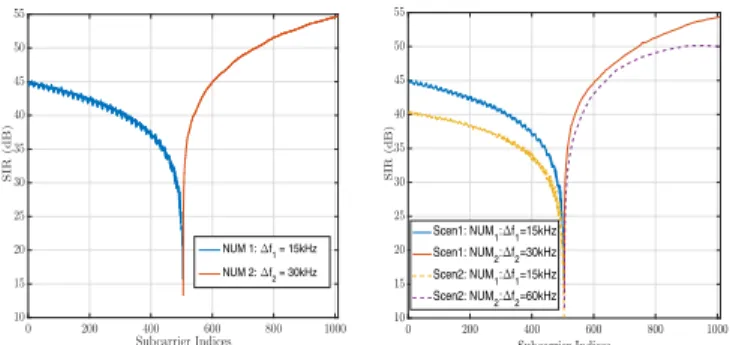
Signal to interference ratio (SIR) performances of two ad-jacent numerologies, N U M1with ∆f1= 15kHz, and N U M2
with ∆f2 = 30kHz are observed. While all other parameters
are set the same for both numerologies, N U M2 exhibits
better performance than N U M1 (Fig. 6(a)). This result is
quite expected because, as explained in the previous section (Section III), it is evident that, for individual CP case, N U M1
is a victim of interference from N U M2 at both, transmitter
and receiver, while N U M2receives interference from N U M1
only at the receiver. That is to say, numerology with small ∆f is more exposed to INI than the one with larger ∆f .
0 200 400 600 800 1000 Subcarrier Indices 10 15 20 25 30 35 40 45 50 55 S IR (d B ) NUM 1: ∆f1 = 15kHz NUM 2: ∆f2 = 30kHz
(a) Performance of numerologies with small and large subcarriers
Scen1: NUM 1: f1=15kHz Scen1: NUM2: f2=30kHz Scen2: NUM 1: f1=15kHz Scen2: NUM2: f2=60kHz
(b) Scenarios with different subcarrier spacing offsets between numerologies
Fig. 6: SIR performances of the numerologies as a function of subcarrier spacing
Another interesting observation regarding subcarrier spacing in the multi-numerology systems is that the SIR performance of each numerology degrades as the subcarrier spacing offset (SSO) (i.e ∆f2 - ∆f1) between them increases (Fig. 6(b)).
This observation again can be linked to the discussion pre-sented in Section III. In Fig. 6(b), two scenarios are prepre-sented: Scenario-1 with ∆f1/∆f2 = 15kHz/30kHz, and Scenario-2
with ∆f1/∆f2 = 15kHz/60kHz.
Numerology-1: In Scenario-1, the ratio ∆f2/∆f1 = 2.
Re-calling our discussion in Section III, only one out of two subcarriers of N U M1 experiences interference from N U M2
at the transmitter, that is, only half of all the subcarriers of N U M1 are affected by INI. However, in Scenario-2, the ratio
∆f2/∆f1 = 4, which causes three out of four subcarriers
of N U M1 to be affected by INI. Therefore, three quarters
of all subcarriers of N U M1 are experiencing interference
from N U M2, leading to poorer SIR performance compared
to Scenario-1.
Numerology-2: The observed degradation on the SIR perfor-mance of N U M2can be understood by considering the signal
processing at the receiver of N U M2. FFT window at the
receiver of N U M2 captures half of the symbol duration of
N U M1 from the composite signal in Scenario-1, and only a
quarter of it in Scenario-2. Therefore, during FFT operation at the receiver of N U M2, Scenario-2 causes more disturbance
on the samples of N U M1 (and hence more severe loss of
orthogonality between its subcarriers) compared to Scenario-1. This imparts higher INI from N U M1to N U M2in Scenario-2
compared to Scenario-1. B. Number of Subcarriers
Throughput of a particular numerology can be increased by increasing its number of subcarriers. In single numerology systems larger number of subcarriers leads to the growth of peak-to-average power ratio (PAPR) problem [14]. However, in multi-numerology systems, apart from PAPR issues, dif-ferent number of subcarriers used in each numerology can be evaluated to have an impact on INI as well. Increased number of subcarriers in one numerology corresponds to the proportional growth of its out of band emission (OOBE) which causes more interference to the adjacent numerology. To investigate the effect of the number of subcarriers on multi numerology system, we considered two simple scenarios shown in Fig. 7. Each user (in both numerologies) has 336 subcarriers in Scenario-1 and, number of Subcarriers for each user of N U M2 is halved in Scenario-2.
336 336 336 Pow er Frequency Scenario-2 : f1= 15 kHz : f2= 30 kHz 336 336 336 Pow er Frequency
Scenario-1 Guard band
EdgeUser EdgeUser MiddleUser Mid.User FarUser FarUser 168 168 168 336 336 336
Fig. 7: Scenarios for number of subcarriers
Fig. 8 summarizes SIR performances for the two investi-gated scenarios. Performances of N U M1 users improve in
Scenario-2 due to the less INI they receive from N U M2
as a result of the reduced number of subcarriers in N U M2.
Improvement in SIRs of middle and far users is higher than that of the edge user because of their larger spectral distance from N U M2. The larger the distance of the user from the
interfering numerology, the lesser the INI it receives. On the other hand, performance of each user of N U M2 is degraded
in Scenario-2. This is because, when the number of the subcarriers of each user is reduced, the users of N U M2 get
closer to N U M1, exposing them to higher interference from
(a) Tx Windowing (b) Rx Windowing (c) Tx Rx Windowing
Fig. 10: SIR performance with windowing operation (roll off factor = 0.5)
Fig. 8: SIR performance for Scenario-1 and 2, with different number of subcarriers
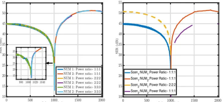
(a) No power offset between nu-merologies
Scen1:NUM1:Power Ratio:- 1:1:1 Scen1:NUM2:Power Ratio:- 1:1:1 Scen2:NUM1:Power Ratio:- 2:2:2 Scen2:NUM2:Power Ratio:- 1:1:1
(b) With power offset between nu-merologies
Fig. 9: SIR performance of the two numerologies as a function of their power offsets.
C. Power Offset
Users can have different power requirements depending on their channel conditions and application. Power difference among the users utilizing the same numerology does not cause any interference since the orthogonality condition is main-tained. However, the power offset (Pof f) between users in two
adjacent numerologies significantly contributes to the amount of INI experienced by each numerology. To illustrate this fact, let us consider an ideal case with two numerologies. In the first scenario, all users in both numerologies are assigned the same
power such that Pof f in the whole system is zero. In this case
the SIR performance of each numerology remains the same regardless the actual power level assigned to the users (as long as Pof f = 0) as depicted in Fig. 9(a). This is because, in this
case, the amount of interference imposed on the users in the victim numerology depends solely on the spectral distance of each user from the interfering numerology.
In the second scenario, we introduce power offset between the two numerologies. Users of the same numerology are scheduled with the same power but the power levels in the two numerologies are different. We consider the result of the first scenario (with zero Pof f) as a baseline for performance
comparison. Fig. 9(b) shows that, with the power offset of 3dB between the two numerologies, the performance of N U M2 is
degraded by about 6dB.
The two scenarios discussed above give an idea about how critical the power offset issue can be in the performance of the multi-numerology systems. In more realistic scenarios, users are often expected to have different power requirements (even if they utilize the same numerology). Now, when power is assigned to each user according to its own need, power offset between numerologies will be random (i.e users in the victim numerology will have different power offsets with each user in the interfering numerology). In such cases, amount of INI experienced by each user in the victim numerology depends not only on the spectral distance of that user from the interfering numerology but also its power offset with each user of the interfering numerology. Proper scheduling technique would be required to minimize the power offsets and optimize performance of each user in the multi-numerology systems [15].
D. Windowing
High out of band emission of the OFDM waveform can be reduced by smoothing the edges of its rectangular pulse. One way of achieving this is through a windowing process where each OFDM symbol is multiplied with a smooth function, such as raised cosine. Windowing can be applied either at the trans-mitter or receiver, or both. Transtrans-mitter windowing reduces the possible spectral leakage to the adjacent numerology whereas receiver windowing provides a better interference rejection at the receiver [16]. Now, with reference to our discussion in Section III, for the two numerologies N U M1, and N U M2
shown in Fig. 3, N U M1 receives INI from N U M2 at both,
transmitter and receiver. Therefore, applying both, transmitter windowing on N U M2 and receiver windowing on N U M1
should significantly improve SIR performance of N U M1.
Also, N U M2 receives INI from N U M1 only at the receiver.
Therefore, receiver windowing on N U M2 is expected to be
sufficient enough to enhance SIR performance of N U M2. This
intuition agrees well with the simulation results presented in Fig. 10.
Simulation was conducted for N U M1 with ∆f1 = 15
kHz and N U M2 with ∆f2 = 30 kHz, and the raised cosine
window was employed by adopting the steps discussed in [16]. Fig. 10(a) shows that transmitter windowing on N U M1
does not cause any significant improvement on performance of N U M2 since power leakage from N U M1 to the subcarriers
of N U M2 at the transmitter is already zero (see Fig. 3).
However, transmitter windowing on N U M2enhances the SIR
performance of N U M1 to some extent. Fig. 10(b) reveals
the effect of receiver windowing when applied alone. Again, receiver windowing on N U M1 only slightly improves its
performance, while outstanding performance is achieved on N U M2 with receiver windowing for the same roll off factor.
Finally, Fig. 10(c) shows that combination of transmitter and receiver windowing significantly improves performance of N U M1 compared to the case when they are applied
alone. For N U M2, the SIR performance with transmitter and
receiver windowing is similar to the case when only receiver windowing is applied. In summary, better SIR performance of the numerology with small ScS can be achieved with both, transmitter windowing on the interfering numerology as well as receiver windowing at its own receiver. But for numerology with larger ScS, only receiver windowing can be enough. E. Guard Band
Employing guard bands (GBs) between adjacent numerolo-gies is another way of reducing the effect of INI at the expense of spectral efficiency of the system. Our simulation result for two numerologies N U M1 with ∆f1 = 15kHz, and N U M2
with ∆f2 = 30kHz shows that GB is effective in improving
SIR performance of the edge subcarriers only. No significant improvement is observed for subcarriers far from the edges as shown in Fig. 11.
V. CONCLUSION
Next generations of wireless systems are geared towards ul-timate flexibility in different aspects. An introduction of multi-numerology concept as a part of this flexibility has brought new problems, such as INI, that require special attention from researchers. This paper has investigated the INI problem and intuitively explained its underlying causes from signal processing point of view at the transmitter and receiver. The paper goes further and investigates the performance of multi-numerology system when coexisting numerologies flexibly adopt different parameters such as subcarrier spacing, number of subcarriers, power, etc. All the relationships observed in this study are supported by simulation results, however it will be extended to provide a thorough mathematical analysis of the INI and the factors affecting it.
0 10 20 30 40 50 60 N o rm a li ze d E V M [P er ce n t] 200 400 600 800 1000 1200 1400 1600 1800 2000 Subcarrier Index 10 20 30 40 50 990 1000 1010 1020 NUM. with GB=0 NUM. with GB= f2 NUM. with GB=2* f2
Fig. 11: EVM plot for different amounts of guard band between numerologies
REFERENCES
[1] 3rd Generation Partnership Project (3GPP), “Study on scenarios and requirements for next generation access technologies; (release 14),” Technical Specification 38.913, ver 14.3.0, Aug. 2017.
[2] E. Dahlman, S. Parkvall, and J. Skold, 4G, LTE-advanced Pro and the Road to 5G. Academic Press, 2016.
[3] 3rd Generation Partnership Project (3GPP), “NR; Physical channels and modulation (Release 15) ,” Technical Specification 38.211, ver 15.1.0, Apr. 2018.
[4] ——, “NR; Base Station (BS) radio transmission and reception (Release 15) ,” Technical Specification 38.104, ver 15.1.0, Apr. 2018.
[5] A. Yazar and H. Arslan, “A Flexibility Metric and Optimization Methods for Mixed Numerologies in 5G and Beyond,” IEEE Access, vol. 6, pp. 3755–3764, 2018.
[6] X. Zhang, L. Zhang, P. Xiao, D. Ma, J. Wei, and Y. Xin, “Mixed Numerologies Interference Analysis and Inter-Numerology Interference Cancellation for Windowed OFDM Systems,” IEEE Transactions on Vehicular Technology, 2018.
[7] B. Pek¨oz, S. K¨ose, and H. Arslan, “Adaptive Windowing of Insufficient CP for Joint Minimization of ISI and ACI Beyond 5G,” in Personal, Indoor, and Mobile Radio Communications (PIMRC), 2017 IEEE 28th Annual International Symposium on. IEEE, 2017, pp. 1–5.
[8] A. F. Demir and H. Arslan, “The Impact of Adaptive Guards for 5G and Beyond,” in Personal, Indoor, and Mobile Radio Communications (PIMRC), 2017 IEEE 28th Annual International Symposium on. IEEE, 2017, pp. 1–5.
[9] A. Yazar, B. Pek¨oz, and H. Arslan, “Flexible Multi-Numerology Systems for 5G New Radio,” arXiv preprint arXiv:1805.02842, 2018.
[10] L. Zhang, A. Ijaz, P. Xiao, A. Quddus, and R. Tafazolli, “Subband Filtered Multi-carrier Systems for Multi-service Wireless Communica-tions,” IEEE Transactions on Wireless Communications, vol. 16, no. 3, pp. 1893–1907, 2017.
[11] J.-Y. Chouinard, X. Wang, and Y. Wu, “MSE-OFDM: A new OFDM transmission technique with improved system performance,” in Acous-tics, Speech, and Signal Processing, 2005. Proceedings.(ICASSP’05). IEEE International Conference on, vol. 3. IEEE, 2005, pp. iii–865. [12] M. Nemati and H. Arslan, “Low ICI Symbol Boundary Alignment for
5G Numerology Design,” IEEE Access, vol. 6, pp. 2356–2366, 2018. [13] A. T. Abusabah and H. Arslan, “NOMA for Multinumerology OFDM
Systems,” Wireless Communications and Mobile Computing, vol. 2018, 2018.
[14] H. Ochiai and H. Imai, “On the Distribution of the Peak-to-average Power Ratio in OFDM Signals,” IEEE transactions on communications, vol. 49, no. 2, pp. 282–289, 2001.
[15] A. Yazar and H. Arslan, “Fairness-Aware Scheduling in Multi-Numerology Based 5G New Radio,” arXiv preprint arXiv:1806.04072, 2018.
[16] E. Bala, J. Li, and R. Yang, “Shaping Spectral Leakage: A Novel Low-complexity Transceiver Architecture for Cognitive Radio,” IEEE Vehicular Technology Magazine, vol. 8, no. 3, pp. 38–46, 2013.
![Fig. 1: Block diagram of the conventional multi-numerology implementation [9]](https://thumb-eu.123doks.com/thumbv2/9libnet/5440053.104309/2.918.127.797.83.279/fig-block-diagram-conventional-multi-numerology-implementation.webp)