On Capacity and Coding for Segmented Deletion
Channels
Feng Wang∗, Defne Aktas† and Tolga M. Duman∗
∗School of Electrical, Computer and Energy Engineering, Arizona State University, Tempe, AZ 85287-5706, USA †Department of Electrical and Electronics Engineering, Bilkent University, Bilkent, Ankara 06800, Turkey
Email: [email protected], [email protected], [email protected]
Abstract— We consider binary deletion channels with a segmentation assumption which appears to be suited for more practical scenarios. Unlike the binary independent and iden-tically distributed (i.i.d.) deletion channel where each bit is independently deleted with an equal probability, the segmentation assumption prohibits certain transmitted bits to be deleted, i.e., in a block of bits of a certain length, only a limited number of deletions can occur. We first propose several upper and lower capacity bounds for the segmented deletion channel. Then we focus on an interleaved concatenation of an outer low-density parity check (LDPC) code with error-correction capabilities and an inner marker code with synchronization capabilities over these channels. With the help of a specifically designed maximum-a-posteriori (MAP) detector, we demonstrate reliable transmission at higher code rates than the existing ones reported in the literature.
I. INTRODUCTION
Channels impaired by insertion, deletion and/or substitution errors, whose positions are unknown to the transmitter and the receiver, are used as appropriate models for systems with imperfect timing-alignment. Due to the memory introduced by the synchronization errors into the received data stream, study of these channels becomes challenging. Many different models of insertion/deletion channels have been proposed in the literature [1], [2], most of which assume that the channel is independent and identically distributed (i.i.d.), i.e., every transmitted bit independently experiences a possible synchronization error with an identical probability.
In this paper, we consider binary deletion channels with the additional segmentation assumption, introduced in [3]. For the segmented deletion channel, the transmitted bits are implicitly partitioned into consecutive disjoint segments (as there is no explicit partitioning step at the transmitter side), each with the same length of b bits. During the transmission, each segment is received intact with probability 1−Pdwhile deletion errors
occur with probability Pd. However, the maximum number
of bits allowed to be deleted per segment is pre-determined. For simplicity, we focus on the scenario where the number of deletions is limited to one bit and assume that the deleted bit is uniformly chosen among b bits of one segment. As a simple example, if the binary sequence 00101101 with a segment length of b = 4 is transmitted, it is possible that the third and fifth bits are deleted, leading to the received sequence 000101.
This work is funded by the National Science Foundation, under contract NSF-TF 0830611.
However, receiving 001001 is impossible since two bits from the second segment would need to be deleted in this case. We are interested in this channel model since the segmentation assumption arises naturally in many practical systems. The reason behind it is that synchronization errors are often due to a mismatch between the clocks of transmitters and receivers, that is, when a deletion error occurs, it may take some number of bits to be received correctly before the next deletion event can occur.
Very few results have been reported on the subject of segmented deletion channel. To the best of our knowledge, there are no results on its capacity characterization in the existing literature. Most existing work on synchronization errors focus on the i.i.d. deletion channel while the deletions in segmented deletion channel are clearly correlated. There is also very little work on practical channel coding over this channel. In [3], codes with zero-error correcting capabilities are designed for the case when only a single deletion/insertion error is allowed per segment,. The key idea is to encode the data sequence so that each segment is a codeword from a 1-deletion/insertion correcting code. Other constraints are also imposed on the codewords which provide a simple left-to-right, segment by segment decoding algorithm. As an example, a codebook containing 12 codewords is found for b = 8, resulting in an overall code rate of R = 0.448. Higher code rates can be achieved for larger b. Although some extensions have also been studied offering higher code rates, these coding algorithms require the check bits and check sums to be known at the receiver side, leading to the need of a perfect side-information channel.
In this paper, we first show that the segmented deletion channel falls into the framework of memoryless synchroniza-tion channels (with non-binary inputs) by a proper applicasynchroniza-tion of Dobrushin’s results [4], and hence the channel capacity theorem applies. Then, we explore several upper and lower bounds on its capacity by providing the transmitter and the receiver with genie-aided information, i.e., which segment has a deletion error. In addition to the capacity upper and lower bounds, we further consider a practical concatenated coding approach, for which concatenation of an outer LDPC code with an inner marker code is explored, as in [5]. Despite the similar encoding procedure over these channels, there are significant differences from the previous work [5] that considers i.i.d. deletion/insertion channels. In particular, the Forty-Ninth Annual Allerton Conference
Allerton House, UIUC, Illinois, USA September 28 - 30, 2011
soft-output synchronization algorithm in [5] is no longer optimal. Therefore, we introduce bit-level and symbol-level MAP detection algorithms which incorporate the segmentation assumption. Our approach is motivated by the fact that if we allow for the use of powerful codes with strong error-correcting capabilities, a much higher code rate (compared to the ones in [3]) can be achieved with a very low probability of error (by dropping the zero-error coding approach).
The rest of the paper is organized as follows. In Section II, we discuss upper and lower bounds for the capacity of the segmented deletion channel. In Section III, we introduce the concatenated coding scheme along with suitable MAP detection algorithms to provide synchronization. Then, in Section IV, simulation results for some practical codes are re-ported. Finally, concluding remarks are provided in Section V.
II. CAPACITYBOUNDS FORSEGMENTEDDELETION
CHANNELS
A. Existence of the Shannon Capacity
We first show that the results of Dobrushin in [4] can be applied directly to the segmented deletion channel model and as a result, the Shannon capacity exists. The key observation is that Dobrushin’s result is more general than the usual set-up that it is applied to, that is, information stability holds for a memoryless channel with synchronization errors and the Shannon capacity exists, even when the channel input and output alphabets are not identical. Observe that the segmented deletion channel model can be equivalently described by a 2b -ary input symbol X′ and a binary sequence of output bits Y′ of varying lengths (e.g., for the elementary segmented deletion channel, of length b or b− 1 bits). It is clear that the model in [4] encompasses as a special case the segmented deletion channel (when the deletions occur independently in different segments). To illustrate this point further, let us give a simple example. Consider the segmented deletion channel with b = 2 and deletion probability of Pd. The equivalent
channel transition matrix P (Y′|X′) is given in Table I. Based on the above explanation, we can safely argue that the segmented deletion channel is information stable, and hence its Shannon capacity exists. In fact, the capacity per transmitted bit is given by
C = lim
T→∞
1
T P (X)maxI(X; Y),
where I(·; ·) is the average mutual information between the input sequence X, of length T , and the output sequence Y.
Although the channel capacity exists, evaluation of the capacity expression is not straightforward, as similar to the case with an i.i.d. deletion channel. That is, there is no single-letter or finite-single-letter formulation which may be amenable for practical computation as in the case of other channel models with synchronization errors. With this observation, we next introduce two trivial upper/lower bounds on the capacity of segmented deletion channels, and then discuss several other tighter bounds on the capacity by providing the transmitter and receiver with some genie-aided information [6].
B. Capacity Upper Bounds
An obvious capacity upper bound for a segmented deletion channel can be obtained by providing side information on the positions of all the deletions to the receiver . Therefore, the channel becomes a binary erasure channel with memory and an erasure probability Pd/b. Since the memory does not affect
the capacity of an erasure channel [7], 1− Pd/b becomes a
trivial upper bound on the channel capacity of the segmented deletion channel.
A tighter upper bound on the capacity can be obtained as follows. Define the random process V ={Vn}Nn=1, where Vn
is a binary valued random variable which determines whether the n-th segment Xnexperiences a deletion error or not. With
the side information being provided to both the transmitter and the receiver, we have
C ≤ 1 bP (Xmaxn)
I(Xn; Yn) ,
where Yn, with length b or b− 1, is the received sequence
corresponding to Xn.
Obviously, 1 − Pd fraction of the blocks see noiseless
channels, and hence can transmit b bits with no error. The remaining Pdfraction of blocks will equivalently see a deletion
channel with b input bits and exactly one deletion at the output. The capacity of such a channel can be determined (for reasonable values of b) using the Blahut-Arimoto Algorithm (BAA) [8], [9]. Denoting the capacity of the deletion channel with b input bits and b−1 output bits as Cd(b, 1), we can write
an upper bound on the capacity of the segmented deletion channel as
C≤ 1 − Pd+ Pd
1
bCd(b, 1). (1)
For large values of b that are not amenable for the BAA, one can resort to the upper bound Cd(B, 1)≤ Cd(b, 1) + (n− 1)b
reported in [6], where B = nb. The bound is tight for large
TABLE I
EXAMPLE OFTRANSITIONPROBABILITYP (Y′|X′)FORb = 2.
X′ Y′= 00 Y′= 01 Y′= 10 Y′= 11 Y′= 0 Y′= 1
0 (00) 1− Pd 0 0 0 Pd 0
1 (01) 0 1− Pd 0 0 Pd/2 Pd/2
2 (10) 0 0 1− Pd 0 Pd/2 Pd/2
B as it is easy to verify that Cd(B, 1)≥ Cd′(b, 1) + (n− 1)b − H ( 1 n ) , (2)
where H(·) is the binary entropy function and Cd′(b, 1) is the achievable rate for a deletion channel with b independent uni-formly distributed (i.u.d.) input bits and exactly one deletion. The gap between the upper and lower bounds of Cd(B, 1)
gets smaller as n increases, since the first two terms are both dominated by (n−1)b and the entropy term H(n1) approaches zero.
C. Capacity Lower Bounds
As a simple approach to obtain a capacity lower bound, assume that a long interleaver has been introduced before transmission, and the corresponding deinterleaver is used at the receiver before decoding. The equivalent channel is then a binary i.i.d. deletion channel. Since this is a specific signaling scheme, any achievable rate over a binary i.i.d. deletion channel with probability Pd/b would be achievable on the
segmented deletion channel.
Tighter capacity lower bounds can be obtained by revealing some side information, as in the approach described in the upper bound, and then subtracting a term to ensure that the obtained result is in fact a lower bound..u Specifically, we have
I(X; Y) = I(X; Y, V)− I(X; V|Y) ≥ I(X; Y, V) − H(V) .
When obtaining the value of I(X; Y, V), we cannot optimize the input distribution for every segment, since the side infor-mation is only provided to the receiver. Instead, we consider the i.u.d. inputs for all the segments. Hence, the following capacity lower bound is deduced
C≥ 1 − Pd+ Pd 1 bC ′ d(b, 1)− 1 bH(Pd), (3) where, as noted before, Cd′(b, 1) refers to the achievable rates with i.u.d. inputs for a b-bit input one-bit deletion channel.
Comparing the capacity upper bound in (1) and lower bound in (3), we see that the difference is
Pd 1 b(Cd(b, 1)− C ′ d(b, 1)) + 1 bH(Pd).
When Pd approaches zero or one, the term 1bH(Pd) tends
to zero. In fact, when Pd equals zero or one, the
segment-level synchronization is naturally achieved and the capacity is exactly as given in (1). Furthermore, note that for large b val-ues, the i.u.d. input sequences are optimal for the calculation of Cd(b, 0). When the overall deletion rate per bit 1b goes to
zero, i.u.d. inputs will be close to optimal, and therefore, we would expect the difference between Cd′(b, 1) and Cd(b, 1) to
be small.
III. CONCATENATEDCODING OVERSEGMENTED
DELETIONCHANNELS
We now focus on a practical channel coding scheme suitable for segmented deletion channels. The proposed encoding and
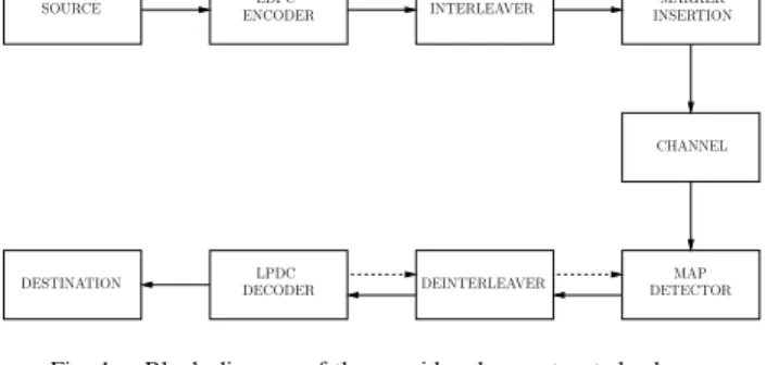
DEINTERLEAVER SOURCE CHANNEL DESTINATION INTERLEAVER LPDC DECODER LDPC ENCODER MARKER MAP DETECTOR INSERTION
Fig. 1. Block diagram of the considered concatenated scheme.
decoding procedure is the same as the one described in [5] as illustrated in Fig. 1. The information bits are first encoded by an outer LDPC code, and then the transmitted sequence is formed by periodically inserting marker bits to the interleaved sequence of coded bits. Marker bits refer to a certain pattern of bits with good synchronization capabilities and are known at both the transmitter and the receiver.
Let xT1 ={xk}Tk=1 and y R
1 = {yn}Rn=1 be the sequences
of bits at the channel input and channel output, respectively, where the number T of transmitted bits is a constant system parameter. We assume T = N b, where N is the total number of segments. According to the channel model, during the transmission, each segment experiences a deletion error with probability Pd and only one bit is allowed to be deleted. The
deleted bit is uniformly chosen among the consecutive b bits. Therefore, the number R of received bits is a random variable taking values in the set{T −N, T −N +1, . . . , T }, depending on the realization of the deletion process. The transmitter and the receiver have no information on the positions of the deletions.
At the receiver side, MAP detection for synchronization purposes is first executed to generate soft information on the transmitted bits by exploiting the marker code struc-ture and the channel model. Next, after being deinterleaved, this information is fed the outer LDPC decoder. If iterative detection/decoding is performed (as opposed to a one-shot detection/decoding), extrinsic information produced by the LDPC decoder is fed back to the channel detector for a new iteration, and the turbo principle is employed [10].
In our previous work [5], MAP detection algorithm was specifically designed for i.i.d. deletion channels. This detector can be directly applied to a segmented deletion channel with a deletion probability for each bit setting to pd = Pd/b.
However, this would be a sub-optimal choice since it ignores the additional information introduced by the segmentation assumption. For example, if the detector determines that the first bit of a segment is deleted, we can naturally deduce that there will be no error in the next b − 1 bits. In the following sections, we describe two other detectors that take the additional segmentation assumption into consideration and provide improved results.
(d,1) (d,0) (d+1,1) 1 -k d
p
dp
d p -1 d p -1 (d,0) (d+1,1) d p -1 dp
1 k k-1 kTransition between two segments Transition inside one segment
Fig. 2. Trellis for bit-level MAP detection.
A. Improved Bit-level Synchronization
The MAP detection algorithm is similar to the general forward backward algorithm (FBA) [10]. Let us introduce a trellis diagram, as shown in Fig. 2, with the state of trellis at time k (when xk is transmitted) defined to be sk = (dk, i),
where dk denotes the number of deletions up to time k and i
is an indicator where i =
{
0 if no deletion in the segment,
1 otherwise. (4)
In this case, we still set the deletion probability for each bit to be pd, which determines the transition probability from state
to state. When xk is not the first bit of a segment, transition
from state (dk− 1, 1) to (dk, 1) or (dk, 0) is prohibited until
the next segment, since there is already one bit deleted in the segment (i = 1) and no more bit can be further deleted.
As in [5], we define the function F (xk, yn) =
{
1 if yn= xk,
0 if yn̸= xk, (5)
and also the forward/backward parameters of FBA in the usual sense, i.e., αk(sk) = P (y1k−dk, sk), βk(sk) =
P (yk−dR k+1|sk).
These coefficients can be computed by means of the fol-lowing forward/backward recursion [11].
Case 1: xk is the first bit of the segment:
αk(sk) = P ( sk= (dk, i), yk−d1 k ) = ipd ( αk−1(dk− 1, 1) + αk−1(dk− 1, 0) ) + (1− i)(1 − pd) ( αk−1(sk) + αk−1(dk, 1) ) ·∑ xk P (xk)F (xk, yk−dk), (6) βk−1(sk−1) = P ( ykR−1−dk−1+1|sk−1= (dk−1, i) ) = (1− i) ( pdβk(dk−1+ 1, 1) + (1− pd)βk(sk−1) ∑ xk P (xk)F (xk, yk−dk) ) + i((1− pd)βk(dk−1, 0) ∑ xk P (xk)F (xk, yk−dk) + pdβk(dk−1+ 1, 1) ) . (7)
Case 2: xk is not the first bit of the segment:
αk(sk) = ipdαk−1(dk− 1, 0) +(1− pd(1− i) ) αk−1(sk) ∑ xk P (xk)F (xk, yk−dk), (8) βk−1(sk−1) = (1− i)pdβk(dk−1+ 1, 1) +(1− pd(1− i) ) βk(sk−1) ∑ xk P (xk)F (xk, yk−dk). (9) We are interested in the exact “frame synchronization” sce-nario, and thereby the forward/backward recursions are initi-ated as α0(sk) = { 1 if sk= (0, 0), 0 otherwise, (10) βT(sk) = 1− Pd if sk= (T − R, 0), Pd if sk= (T − R, 1), 0 otherwise. (11) Finally, the target probability can be computed as
Case 1: P (yR1|xk) = (1− pd) k/b ∑ dk=0 1 ∑ i=0 αk−1(dk, i)βk(dk, 0) ·F (xk, yk−dk) +pd k/b ∑ dk=0 1 ∑ i=0 αk−1(dk− 1, i)βk(dk, 1), (12) Case 2: P (y1R|xk) = k/b ∑ dk=0 1 ∑ i=0 ( 1− pd(1− i) ) αk−1(dk, i)βk(dk, i) ·F (xk, yk−dk) +pd k/b ∑ dk=0 αk−1(dk− 1, 0)βk(dk, 1). (13) B. Symbol-level Synchronization
The MAP detection algorithm we described above is not optimal [5]. However, the symbol-level MAP detector [5] can be easily applied under this scenario by treating one segment as a whole symbol, which provides an improved channel detection algorithm.
Define the binary event Dk,n, with k∈ {1, 2, . . . , N} and
n ∈ {1, 2, . . . , R}, which denotes whether, after the first k transmitted segments of bits, exactly n bits are received or not. Thanks to the assumption of 1-deletion per segment, symbol-level MAP detection becomes feasible for large values of b, and the forward/backward recursions are given as
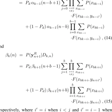
= Pdαk−1(n−b +1) b−1 ∑ j=0 b−1∏ i=0 i̸=j ∑ xbk−i P (xbk−i) ·F (xbk−i, yn−i′) + (1− Pd) αk−1(n−b) b−1 ∏ i=0 ∑ xbk−i P (xbk−i) ·F (xbk−i, yn−i) , (14) and βk(n) = P (yRn+1|Dk,n) = Pdβk+1(n+b−1) b ∑ j=1 b ∏ i=1 i̸=j ∑ xbk+i P (xbk+i) ·F (xbk+i, yn+i′) + (1− Pd) βk+1(n+b) b ∏ i=1 ∑ xbk+i P (xbk+i) ·F (xbk+i, yn+i) , (15)
respectively, where i′ = i when i < j and i′ = i− 1 when i > j. The final soft output information is generated as p(y1R|xbk−1, . . . , xbk) = Pd min(bk,R)∑ n=0 b−1 ∑ j=0 αk−1(n−b +1)βk(n) b∏−1 i=0 i̸=j F (xbk−i, yn−i′) +(1− Pd) min(bk,R)∑ n=0 αk−1(n−b)βk(n) b−1∏ i=0 F (xbk−i, yn−i).(16) IV. NUMERICALEXAMPLES
As an example of capacity bounds on the segmented dele-tion channel, we consider the case with b = 12, and plot the upper and lower bounds on the capacity as a function of the deletion probability Pd. The trivial capacity upper bound
1−Pd/b and lower bound for i.i.d. deletion channel [1] with a
deletion rate Pd/b are also included. It is clear that the capacity
bounds obtained from (1) and (3) improve the trivial ones. In the remainder of the section, we consider practical coding schemes with the aim of confirming the performance gain over the existing techniques. The only reported practical coding scheme is introduced in [3], where for b = 8 the code rate is 0.448. This code is able to achieve zero error when at most one deletion error occurs per segment. Although codes with higher rates are also provided which allow for low practical error rates, we will not consider them in our paper. The reason behind is that certain information generated from the transmitted sequence, e.g., parity check bits, is assumed to be known at the receiver, which requires another ideal channel to communicate.
In Fig. 4, we compare the bit error (BER) performance of several detectors with a single-pass decoding, i.e., MAP detection for synchronization is only executed once. We adopt a randomly picked binary LDPC code with rate 0.78, length 4521 and insert the marker “01” every 15 LDPC-coded bits.
0 0.1 0.2 0.3 0.4 0.5 0.7 0.75 0.8 0.85 0.9 0.95 1 Pd
rate in bits/channel use
trivial UB UB in Eqn. (1) LB from [1] LB in Eqn. (3)
Fig. 3. Bounds on the segmented deletion capacity with b = 12.
10−1 10−5 10−4 10−3 10−2 10−1 Pd BER b = 8, bit MAP b = 8, improved bit MAP b = 16, bit MAP b = 16, improved bit MAP b = 8, symbol MAP b = 16, symbol MAP
Fig. 4. BER performance of different MAP detectors.
Obviously, symbol-level MAP detection with iterative soft demapping [12] outperforms other detectors. However, for large b, it becomes infeasible. One solution to the increased complexity problem is to consider only the M largest soft values among the 2b outputs as in the greedy multiuser detection algorithm [13]. Another observation is that the bit-level MAP detector for the i.i.d. deletion channel [5] works well at low deletion rates. With the same overall code rate R = 0.693 and a single-pass decoding, the bit-level MAP detector for the i.i.d. deletion channel provides almost the same performance as the one discussed in Section III-A. This is not surprising since the segmentation assumption may not provide additional information to the detector due to the limited number of deletions under this regime.
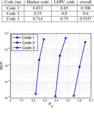
For further illustration, we apply the multiple-pass decoding algorithm, i.e., iterations between the MAP detector and LDPC decoder are allowed, and use the LDPC codes (with length 10000) optimized for the AWGN channels. The rates
TABLE II
RATES FORSIMULATEDCODES
Code rate Marker code LDPC code overall
Code 1 0.833 0.85 0.708 Code 2 0.75 0.8 0.6 Code 3 0.714 0.75 0.5357 0 0.1 0.2 0.3 0.4 0.5 0.6 0.7 10−5 10−4 10−3 10−2 10−1 Pd BER Code 1 Code 2 Code 3
Fig. 5. BER performance for multiple-pass decoding algorithm (b=8).
of adopted channel codes are specified in Table II, where the marker code rates are optimized for segmented deletion channels with Pd = 0.3, 0.5 and 0.7, respectively [5]. The
resulting error rate performance is plotted in Fig. 5. It is obvious that the concatenated coding scheme can achieve a higher code rate when Pd
b gets smaller. We note, however,
that the results obtained are not very close to the capacity bounds. For instance, if we consider an error rate of 10−3 as reliable communications, from Fig. 5, the corresponding Pdfor
these three codes are 0.24, 0.42 and 0.6, while the capacity lower bounds for these values are 0.812, 0.723 and 0.658, respectively. A difference of 0.1 bits per channel use exists between the capacity lower bounds and the actually achieved code rates with the practical channel coding approach, indicat-ing that there is room for improvement with more sophisticated channel coding solutions.
V. CONCLUSIONS
In this paper, we have considered channels with synchro-nization errors modeled by a bit deletion process with an additional segmentation assumption. We have first argued that such channels are information stable, and their channel capacity exists. Then, we introduced several upper and lower bounds in an attempt to understand the channel capacity behavior. The approach utilizes a suitable application of a method developed for the case of i.i.d. deletion channels. The results indicate that even though when the deletion probability is near zero or near unity (for each segment), the upper and lower bounds behave similarly, there is a wide-range
of deletion probabilities where they are far apart, and hence there is clearly room for improvement (in terms of obtaining tighter capacity bounds). In the second part of the paper, we have considered a practical channel coding approach over a segmented deletion channel. Specifically, outer LDPC codes concatenated with inner marker codes are utilized, and suitable channel detection algorithms are developed. Different MAP based channel synchronization algorithms operating at either the bit level or the symbol level are introduced. Simulation results with the proposed approach clearly indicate the advan-tages of powerful channel codes (in this case LDPC codes) combined with inner marker codes. In particular, for the entire range of deletion probabilities less than unity, the proposed approach offers a significantly larger transmission rate than the only other alternative solution of the zero-error codes designed in [3].
REFERENCES
[1] R. G. Gallager, “Sequential decoding for binary channels with noise and synchronization errors,” MIT Lincoln Lab., Tech. Rep., Oct. 1961. [2] M. C. Davey and D. J. Mackay, “Reliable communication over channels
with insertions, deletions and substitutions,” IEEE Trans. on Information
Theory, vol. 47, no. 2, pp. 687–698, Feb. 2001.
[3] Z. Liu and M. Mitzenmacher, “Codes for deletion and insertion channels with segmented errors,” IEEE Trans. on Information Theory, vol. 56, no. 1, pp. 224–232, Jan. 2010.
[4] R. L. Dobrushin, “Shannon’s theorems for channels with synchronization errors,” Problems of Information Transmission, vol. 3, no. 4, pp. 11–26, 1967.
[5] F. Wang, D. Fertonani, and T. M. Duman, “Symbol-level synchronization and LDPC code design for insertion/deletion channels,” IEEE Trans. on
Communications, vol. 59, no. 5, pp. 1287–1297, May 2011.
[6] D. Fertonani and T. M. Duman, “Novel bounds on the capacity of the binary deletion channel,” IEEE Trans. on Information Theory, vol. 56, no. 6, pp. 2753–2765, June 2010.
[7] S. Verdu and T. Weissman, “The information lost in erasures,” IEEE
Trans. on Information Theory, vol. 54, no. 11, pp. 5030–5058, Nov.
2008.
[8] S. Arimoto, “An algorithm for calculating the capacity of an arbitrary discrete memoryless channel,” IEEE Trans. on Information Theory, vol. 18, pp. 14–20, Jan. 1972.
[9] R. E. Blahut, “Computation of channel capacity and rate distortion functions,” IEEE Trans. on Information Theory, vol. 18, pp. 460–473, Jan. 1972.
[10] F. R. Kschischang, B. J. Frey, and H.-A. Loeliger, “Factor graphs and the sum-product algorithm,” IEEE Trans. on Information Theory, vol. 47, pp. 498–519, Feb. 2001.
[11] L. R. Bahl and F. Jelinek, “Decoding for channels with insertions, deletions, and substitutions with applications to speech recognition,”
IEEE Trans. on Information Theory, vol. 21, pp. 404–411, Jul. 1975.
[12] X. Li and J. A. Ritcey, “Bit-interleaved coded modulation with iterative decoding,” IEEE Commun. Letters, vol. 1, no. 6, pp. 169–171, Nov. 1997.
[13] A. A. AlRustamani, A. D. Damnjanovic, and B. R. Vojcic, “Turbo greedy multiuser detection,” IEEE J. Select Areas Commun., vol. 19, no. 8, pp. 1638–1645, Aug. 2001.