Real-time multiple SLM color holographic display using
multiple GPU acceleration
Fahri Yara¸s, Hoonjong Kang, Levent Onural Bilkent University, 06800 Ankara, Turkey
[email protected], [email protected], [email protected]
Abstract: A real-time color holographic video display system computes holograms from point cloud of a rigid object by using multi-GPU system and uses three different colored LEDs for recon-struction. Experimental results are satisfactory.
c
° 2009 Optical Society of America
OCIS codes: (090.5694) Real-time holography; (090.2870) Holographic display; (090.4220) Multiplex holography
1. Introduction
Computation of fringe pattern is a severe bottleneck in real-time holographic display systems. Computation time for generating megapixel scale fringe patterns can take tens of seconds [1]. There are also some proposed methods for fast computation [3, 4, 5]. In our system we used Accurate Compensated Phase-Added Stereogram (ACPAS) method that is proposed by Kang [2]. They used the term ”accurate” to emphasize that reconstructed images are quite similar to the reconstructions from the Fresnel hologram. ACPAS, which is one of the coherent stereogram algorithms, has two quality improvement methods, phase compensation and reduction of quantization step. Although it takes slightly longer time than the CPAS [6], it gives more clear reconstructed image as good as the Fresnel hologram.
In our system we used phase-only in-line holograms and we benefit from their advantageous properties such as high diffraction efficiency, low-power diffraction orders and low-power undiffracted beam [7]. Holographic reconstructions by using phase-only spatial light modulators are reported in [8]. In many electro-holographic systems lasers are used. Since it is a coherent light source, speckle noise corrupts the reconstructions. In order to eliminate that effect and make the reconstructions visible by naked eye, LEDs were used in this system. Compared to lasers, LEDs are low cost and easy to operate. However due to low coherence properties, holographic reconstruction quality might degrade. We used three phase-only SLMs and three different color LEDs to have full color holographic reconstructions. The computer graphic card drives the SLMs and red, green and blue channels are controlled in parallel. We used three separate but synchronized SLMs for red, green and blue channels. Phase holograms that are calculated in real-time by using ACPAS algorithm are sent through network using TCP/IP protocols. The display system receives those phase holograms and loads to the SLMs; each SLMs is illuminated by the corresponding LEDs.
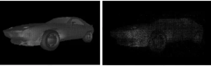
Fig. 1. (a) A 3D model, (b) Computer reconstruction using ACPAS algorithm
2. Experimental Setup
In our experiments we used phase holograms that are generated using ACPAS algorithm in real-time. Our rigid 3D model, shown in Fig. 1, consists of approximately 3000 points and makes a spinning movement in the video. For every point, 3D coordinate information and RGB color values are kept in the model file. This file is dynamic and stored data is being recalculated according to the displayed frame. There are three main stages in the system; client, server and optics. The model file is stored in the client. At first; for each frame the calculated 3D coordinate information and RGB color values are sent online to server through the network using TCP/IP protocol. The server takes 3D coordinate and texture information from client and generate phase hologram of the corresponding 3D frame of the video. The
a495_1.pdf
DWA4.pdf
© 2009 OSA/DH/FTS/HISE/NTM/OTA 2009
DWA4.pdf
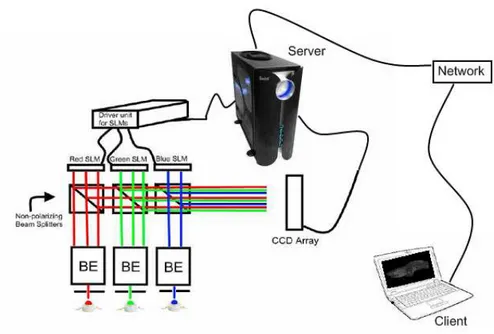
Fig. 2. Optical setup. BE: Beam Expander
generated phase hologram has three components; for red, green and blue components are output in an RGB image. With the help of the computer graphic card of the server, holograms that are having different color information are easily directed to the corresponding SLMs. At the last stage of the system, those SLMs are illuminated by the LEDs. As shown in Fig. 2, we adjusted and overlapped all three colors to have an optical colored reconstruction with the help of high precision stages.
Fig. 3. Performance chart for multi-GPU system for different output sizes. For example, “FC 1M 3GPU”means one megapixel frames by using three GPUs
The client computer has 2GB of RAM, 2.0GHz Intel Core Duo processor. The server has two Quad Core Intel Xeon E5405 2.0GHz with 12MB cache processor, 8GB RAM and two Nvidia GTX 280 AMP (512Bit) with 1GB DDR3 GPUs. For the optics stage, we used HoloEye’s HEO1080P phase-only spatial light modulators. Number of pixels is 1920x1080 with 8µmx8µm square pixel area. Reconstructions were taken with a 11 megapixel CCD array without using any supporting optics. Size of the reconstructions is in the order of the SLM size (about 1.5 x 1.0 cm) and the distance of the reconstructions from the SLM is about 10cm. As seen in Fig. 2 we have used three 1W Edixeon LEDs as light sources. The red, blue and green wavelengths are around 625nm, 460nm and 520nm, respectively. The emitted light from LEDs are passed through a pinhole to narrow the spectrum further. The beam expanders are
a495_1.pdf
DWA4.pdf
© 2009 OSA/DH/FTS/HISE/NTM/OTA 2009
DWA4.pdf
used for uniform planar illumination. After setting up all LEDs, pinholes, expanders and SLMs, reconstructed color components are combined by using beam splitters.
3. Results
In table 1, we have reported the performance analysis of our system. We compare the output fringe pattern and the frame rate. We can interpret that the frame rate is halved when the output size is doubled. This may imply linearity between size of the output and the frame rate. In Fig. 3 we have also compare the performances of the systems with one, two and three GPU systems for different output fringe pattern sizes. In Fig. 1(a) and Fig. 1(b) 3D model and computer reconstruction using ACPAS is shown, respectively. Optical reconstruction of a single frame of the 3D object is shown in Fig. 4. Phase hologram that is used for this optical reconstruction is calculated by using two GPUs.
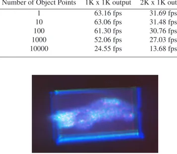
Table 1. Performance analysis for the system with two GPU Number of Object Points 1K x 1K output 2K x 1K output
1 63.16 fps 31.69 fps
10 63.06 fps 31.48 fps
100 61.30 fps 30.76 fps
1000 52.06 fps 27.03 fps
10000 24.55 fps 13.68 fps
Fig. 4. Optical reconstruction of a single frame of the 3D object. Phase hologram calculated by using two GPUs.
4. Conclusions
It is observed that the proposed system can be used as a color holographic video display. Although there is some flicker effect at the reconstructed 3D video, the output frame rate is still enough to observe motion and 3D information. With the help of additional GPU systems, desirable frame rates can be achievable using same setup and algorithms. Acknowledgement
This work is supported by EC within FP7 under Grant 216105 with the acronym Real 3D. References
1. P. St. Hilaire, S. A. Benton, M. Lucente, M. L. Jepsen, J. Kollin, H. Yoshikawa, and J. Underkoffler, “Electronic display system for computa-tional holography,” Proc. SPIE. 1212, 174–182 (1990).
2. H. Kang, “Quality improvements of the coherent holographic stereogram for natural 3D display and its applications,” PhD. Thesis, Nihon University (2008).
3. K. Taima, H. Ueda, H. Okamoto, T. Kubota, Y. Nakamura, H. Nishida, H. Takahashi, and E. Shimizu, “New approach to the interactive holographic display system,” Proc. SPIE. 2176, 23–29 (1994).
4. J. A. Watlington, M. Lucente, C. J. Sparrell, V. M. Bove, and I. Tamitani, “A hardware architecture for rapid generation of electro-holographic fringe patterns,” Proc. SPIE. 2406, 172–183 (1995).
5. H. Yoshikawa and T. Yamaguchi, “Fast hologram calculation for holographic video display,” Proc. SPIE. 6027, 561–566 (2006).
6. H. Kang, T. Fujii, T. Yamaguchi, and H. Yoshikawa, “Compensated phase-added stereogram for real-time holographic display,” Opt. Eng. 46(9), 095802 (2007).
7. L. Lesem , P. Hirsch, and J. J. Jr., “The kinoform: a new wave front reconstruction device,” IBM J. Res. Dev. 13, 150155 (1969).
8. F Yaras, M. Kovachev, R. Ilieva, M. Agour, L. Onural, “Holographic Reconstructions Using Phase-Only Spatial Light Modulators," 3DTV Conference: The True Vision - Capture, Transmission and Display of 3D Video, 2008 pp.PD-1-PD-4 (2008)
a495_1.pdf
DWA4.pdf
© 2009 OSA/DH/FTS/HISE/NTM/OTA 2009