Experimental verification
of metamaterial loaded
small patch antennas
Kamil Boratay Alici
Department of Physics, Nanotechnology Research Center, Bilkent University,
Ankara, Turkey and
Institute of Fusion Studies, The University of Texas at Austin,
Austin, Texas, USA
Mehmet Deniz Caliskan
Nanotechnology Research Center, Bilkent University, Ankara, Turkey
Filiberto Bilotti, Alessandro Toscano and Lucio Vegni
Department of Applied Electronics, “Roma Tre” University, Rome, Italy, and
Ekmel Ozbay
Department of Physics, Department of Electrical and Electronics Engineering,
Nanotechnology Research Center, Bilkent University, Ankara, Turkey
Abstract
Purpose – Metamaterial unit cells composed of deep subwavelength resonators brought up new aspects to the antenna miniaturization problem. The paper experimentally demonstrates a metamaterial-inspired miniaturization method for circular patch antennas. In the proposed layouts, the space between the patch and the ground plane is filled with a proper metamaterial composed of either multiple split-ring or spiral resonators (SRs). The authors have manufactured two different patch antennas, achieving an electrical size of l/3.69 and l/8.26, respectively. The paper aims to discuss these issues.
Design/methodology/approach – The operation of such a radiative component has been predicted by using a simple theoretical formulation based on the cavity model. The experimental characterization of the antenna has been performed by using a HP8510C vector network analyzer, standard horn antennas, automated rotary stages, coaxial cables with 50 V characteristic impedance and absorbers. Before the characterization measurements we performed a full two-port calibration. Findings – Electrically small circular patch antennas loaded with single layer metamaterials experimentally demonstrated to acceptable figures of merit for applications. The proposed miniaturization technique is potentially promising for antenna applications and the results presented in the paper constitute a relevant proof for the usefulness of the metamaterial concepts in antenna miniaturization problems.
Originality/value – Rigorous experimental characterization of several meta material loaded antennas and proof of principle results were provided.
Keywords Antenna, Metamaterials, Materials, Electricity Paper type Research paper
The current issue and full text archive of this journal is available at www.emeraldinsight.com/0332-1649.htm
This work is supported by the European Union under the projects EU-PHOME, and EU-ECONAM, and TUBITAK under Project Nos, 107A004, and 107A012. One of the authors (Ekmel Ozbay) also acknowledges partial support from the Turkish Academy of Sciences. COMPEL: The International Journal
for Computation and Mathematics in Electrical and Electronic Engineering Vol. 32 No. 6, 2013
pp. 1834-1844
q Emerald Group Publishing Limited
0332-1649
DOI 10.1108/COMPEL-10-2012-0276
COMPEL
32,6
I. Introduction
The electrical size of an antenna is found by considering the minimum radius a of a hypothetical sphere enclosing the component divided by the free-space wavelengthl
at the operation frequency (Wheeler, 1947; Chu, 1948; Hansen, 1981). The typical size of a resonant antenna, whatever the technology is (e.g. dipolar, microstrip, dielectric, etc.), is dictated by the free-space wavelength and it is approximately equal tol/2 (Balanis, 1997). In order to design electrically small antennas, which are nowadays ever more desirable, we need to tune the antenna operation frequency by compensating the input reactance and matching the input resistance. Electrically small antennas, however, are subject to several limitations in terms of their efficiency and bandwidth (BW) of operation. Chu derived a relation between the electrical size of an antenna and its minimum quality factor (Chu, 1948). Recent studies, then, have further clarified the fundamental limitations of antennas, shading more light on the relations between the electrical size and both BW and efficiency (Sten et al., 2001; McLean, 1996; Geyi et al., 2000). However, electrically small real antennas are rather far from the fundamental limitations, which typically refer to ideal antennas.
In the continuous research on electrically small antennas, metamaterials (Bilotti and Sevgi, 2012) have played a key role, providing new concepts and new possibilities to approach ever more closely the fundamental limitations. Metamaterials are artificial materials owing ad hoc engineered properties, which allow to overcome the performances of regular components based on conventional materials (Cakmak et al., 2009; Soukoulis et al., 2006; Bilotti et al., 2009, 2010, 2011a, b, c; Tricarico et al., 2010a, b; Monti et al., 2011, 2012; Di Palma et al., 2012a, b).
The unusual properties and ability to control the electromagnetic field enabled by metamaterials inspired researchers to design conceptually new antennas (Ziolkowski and Kipple, 2003; Alu` et al., 2007b; Ziolkowski and Erentok, 2006; Erentok and Ziolkowski, 2008; Alici and Ozbay, 2007a, b; Alici et al., 2010; Bilotti et al., 2012; Barbuto et al., 2012; Qureshi and Eleftheriades, 2005; Ermutlu et al., 2005; Ikonen et al., 2006; Buell et al., 2006). Several approaches have been used, based on different particular metamaterials: double-negative (DNG) (Ziolkowski and Kipple, 2003), single-negative (SNG) (Alu` et al., 2007b), epsilon-negative (ENG) (Ziolkowski and Erentok, 2006; Erentok and Ziolkowski, 2008), mu-negative (MNG) (Ziolkowski and Erentok, 2006; Erentok and Ziolkowski, 2008) metamaterials; single (Alici and Ozbay, 2007a, b) and dual (Alici et al., 2010) mode split ring resonator antennas; single metamaterial inclusions or arrays of inclusions (Bilotti et al., 2012; Barbuto et al., 2012; Qureshi and Eleftheriades, 2005); metasurfaces (Ermutlu et al., 2005); magneto-dielectric materials (Ikonen et al., 2006; Buell et al., 2006).
In this paper, we present the experimental results that demonstrate the feasibility and the effectiveness of the design proposed by Bilotti et al. (2008), concerning an electrically small circular patch antenna loaded by a proper metamaterial characterized by a negative effective permeability. The operation of such a radiative component has been predicted in Alu et al. (2007a), by using a simple theoretical formulation based on the cavity model. That formulation has allowed us deriving the necessary conditions in terms of the filling volume fraction of the metamaterial underneath the patch and the value of the negative permeability of the filling metamaterial. In order to implement and fabricate the required metamaterial, then, we have used the metamaterial resonators introduced by some of the authors in Bilotti et al. (2007a, b), Alici et al.
Experimental
verification
(2007, 2009) and Alici and Ozbay (2009a, b): the multiple split-ring resonators (MSRRs) and the spiral resonators (SRs). Two different prototypes have been fabricated, based on the two different metamaterial resonators, respectively. The details about the fabrication of the prototypes and the results of the experimental characterization of the antennas are reported in the following sections.
II. Antenna configuration
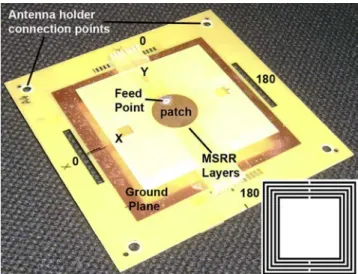
The first fabricated antenna consists of a ground plane and a circular patch, with perpendicularly oriented MSRR layers in between. As shown in Figure 1, the fabricated metamaterial consists of eight closely packed MSRR layers, having one, two, three or four unit-cell resonators along the x-direction. We have arranged the layers in such a way to form a cylindrically shaped MSRR medium with radius r ¼ 6.8 mm and the height equal to the separation between the patch and the ground plane. The ratio between the radii of the patch and of the MSRR medium has been set to R/r ¼ 10/6.8 ¼ 1.47. The metamaterial cylindrical sample has been embedded in a foam material (with relative permeability equal to 1) so that it looks like surrounded by air. While the relative permeability of host material is mair¼ 1, the one of the
metamaterial exhibits a Lorentzian behavior getting positive and negative values at different frequencies.
For the demonstration of the first prototype of the antenna, we have selected a specific MSRR with the following parameters: side length l ¼ 3.2 mm, number of rings N ¼ 8, separation between the rings s ¼ 0.1 mm, width of the strips w ¼ 0.1 mm, split width g ¼ 0.1 mm, thickness of the deposited metal h ¼ 0.018 mm. All the resonators have been printed on an FR-4 dielectric slab with thickness t ¼ 1 mm, relative permittivity 1r¼ 4.9, and dissipation factor tand¼ 0.02. The coaxial SMA connector has been
soldered to ground plane from the bottom and the feeding wire soldered to the patch from the top. The metamaterial layers have been mechanically connected to the ground plane via FR-4 sticks and grids. The feed point of the antenna has been set to approximately
Figure 1. Manufactured antenna photograph and multiple-split ring resonator geometry
COMPEL
32,6
1836
2.5 mm away from the patch edge. We have connected the antenna to an antenna holder from the corners of the ground plane for the characterization measurements. The final configuration of the antenna is shown in Figure 1.
III. Characterization
The experimental characterization of the antenna has been performed by using a HP8510C vector network analyzer, standard horn antennas, automated rotary stages, coaxial cables with 50 V characteristic impedance and absorbers. Before the characterization measurements we performed a full two-port calibration.
III.1 Matching properties
The measured data of the reflection coefficient at the input port of the antenna are reported in Figure 2. Among the different reflection peaks appearing in the plot, we have investigated the ones corresponding to the antenna operation at four different frequencies around the resonance frequency of the MSRRs (4.5 GHz): 3.85, 4.49, 5.07 and 6.26 GHz. As a preliminary step of the characterization, we have found the radius of the minimum sphere that encloses the antenna. The minimum radius for this antenna is a ¼ (102þ 3.42
)0.5¼ 10.56 mm. Then, we can calculate the antenna electrical size, the radiation quality factor Q, the fractional BW (FBW ¼Df/f0, whereDf is the half power
BW and f0is the center frequency), and the 2 10 dB BW. Here, due to the coupling of
several modes, it was not trivial to calculate the FBW. Thereby for the determination of FBW, we have also considered the normalized far field forward transmission at 908, as shown in Figure 2 (dashed curve). The radiation quality factor is a quite important parameter for the performance of electrically small antennas. It is the ratio of the maximum energy stored to the total energy lost per angular period. The minimum Q(Qmin) was estimated by the formula (McLean, 1996): Q ¼ (2k3a3)2 1þ (ka)2 1, here k is
the wavenumber at the operation frequency. For the first mode (3.85 GHz) of the antenna, the minimum quality factor is Qmin¼ 1.98 (the calculated Qs for the other modes are
reported in the Table I). The radiation quality factor calculated from the measured data
Figure 2. Reflection coefficient magnitude (jS11j) and
co-polar far field transmission at 908
Experimental
verification
of Figure 2 is Qrad¼ 5.42. We have used the Foster reactance theorem in this calculation:
Q ¼ 1/BW (Geyi et al., 2000). The FBW and electrical size at the first mode are 0.18 and
l/3.69, respectively. We note that the antenna is close to the Chu limit. III.2 Radiation properties
Transmission measurements between the antenna feed and a generic probe placed in the far-field allow determining the radiation properties of the antenna. We have performed direct far-field measurements on the two principal planes. Far-field distance R has been determined as the maximum between 10lat the operation frequency and 2D2/l, where D is the maximum linear dimension of the antenna. A standard gain horn antenna has been used as the receiver.
In Figure 3, we show the frequency dependent co-polar angular scan measurements, which are not normalized to the peak gain. From these data, we can see that at the minima of the reflection coefficient amplitude jS11j, the transmitted power is rather high.
In Figure 3(a) and (b), we show the yz-plane and xz-plane cuts as a function of frequency, respectively. These patterns have been scaled to the maximum gain. The peak gain of the antenna has been calculated by using the two antenna method reported in Balanis (1997). After the full two port calibration, we have first measured the forward transmission for two horn antennas and found the gain of the receiver antenna (G0r)dBin dB. Then, we have replaced one of the horns with the antenna under
test and found the gain of the transmitting antenna (G0t)dB. The separation between the
antennas has been set to R ¼ 800 mm. We have found the gain of the loaded patch at 3.85 GHz by using the formula: (G0r)dBþ (G0r)dB¼ 20 log10(4PR/l) þ 10 log10(Pr/Pt),
where Prand Ptare the received and transmitted power, respectively. The peak gain of
the antenna has been found to be equal to 4.42 dB (Figure 4).
From the far field pattern cuts the half-power beam-widths on the two principal planes have been obtained asuxz¼ 73.58 anduyz¼ 828. The maximum directivity of
the antenna can be calculated approximately from the following formula: D0¼ 41,253/(uxz*uyz). The maximum directivity at 3.85 GHz is, thus, D0¼ 6.84. The
efficiency of the antenna has been calculated from G0(dB) ¼ 10
log10[etD0(dimensionless)] and at 3.85 GHz is 40 percent.
Likewise, the minimum value for Q, also the peak gain is subject to a fundamental limit. The analysis can be performed by plotting the maximum of G/Q with respect to ka. Our ka is around 1 for the modes of interest and, thereby (G/Q)max is around 10. We have
calculated the maximum achievable gain by using the expression Gmax¼ Qmin*(G/Q)max
and found out that for our antenna it is approximately Gmax¼ 17.
In Tables I and II we have reported the main parameters of the different modes. At 6.26 GHz the gain and, thereby, the efficiency of the antenna are rather high with respect to the first mode, but the antenna electrical size is 1.6 times larger.
Freq. (GHz) a (mm) Electrical size ka FBW Rad Q Min Q
A1-Mode1 3.85 10.56 l/3.69 0.85 0.18 5.42 1.98 A1-Mode2 4.49 10.56 l/3.16 0.99 0.07 14.03 1.52 A1-Mode3 5.07 10.56 l/2.80 1.12 0.05 20.28 1.25 A1-Mode4 6.26 10.56 l/2.28 1.38 0.19 5.13 0.91 A2-Mode1 0.88 20.62 l/8.26 0.38 0.04 28.38 11.72 Table I.
Q values extracted from the input reflection coefficient (S11) data
COMPEL
32,6
IV. SR loaded circular patch antenna
In order to further reduce the electrical dimensions of the antenna, we can use electrically smaller metamaterial resonators, such as the SRs. The same fabrication and characterization techniques presented in the previous sections have been used with the only difference that the metamaterial resonator is this time a conducting spiral with the following parameters: side length l ¼ 5 mm, number of turns N ¼ 5, separation between the strips s ¼ 0.1 mm, width of the strips w ¼ 0.1 mm, thickness of the deposited copper metal h ¼ 0.009 mm, substrate thickness t ¼ 0.254 mm. This time the substrate material is the Rogers RT/duroid with relative permittivity 1r¼ 2 and loss
tangent tand¼ 0.0009. Since we expected a more concentrated field in the SRs, in fact,
Figure 3. Frequency dependent angular far field patterns
(a)
(b)
Notes: (a) yz-plane; (b) xz-plane
Experimental
verification
we had to use a substrate with lower losses. The coaxial SMA connector has been soldered to a 0.5 mm thick ground plane from the bottom and the feed point is approximately 5 mm away from the patch edge. A photograph of this antenna is shown in Figure 5. This time we could only measure the S11related parameters, due to the
experimental limitations at lower frequencies.
The minimum radius of the antenna is a ¼ 20.62 mm and the jS11j data are shown
in Figure 6. The ratio between the radii of the patch and SR medium is R/r ¼ 20/14 ¼ 1.43. Similar to the MSRR loaded antenna, we have observed the modes at the frequencies close to the resonance frequency of the SRs. However, this time the first mode is at 0.88 GHz and the electrical size is l/8.3. The values of the relevant antenna parameters are: FBW ¼ 0.035, Qmin¼ 11.7, Qrad¼ 28.4. The minimum value
of the quality factor is again close to the best ideal performance determined by the Chu limit.
Freq. (GHz) Gmax Gain (dB) D0 Efficiency (%)
A1-Mode1 3.85 17.84 4.42 6.85 40 A1-Mode2 4.49 15.16 0.76 5.15 23 A1-Mode3 5.07 13.70 2 1.92 12.79 5 A1-Mode4 6.26 11.83 7.11 7.54 68 A2-Mode1 0.88 – – – – Table II.
Q values extracted from forward transmission (S21) data
Figure 4.
Far field pattern cuts for four different operation modes
(a)
(b)
Notes: (a) yz-plane; (b) xz-plane
COMPEL
32,6
V. Discussions
In Bilotti et al. (2007a) and Alici et al. (2007), we have experimentally confirmed resonators with side length as small asl/100. In principle, thus, we can experimentally confirm the circular patch antenna operation at even smaller electrical sizes. However, we have faced with two major obstacles:
(1) current fabrication technology; and (2) our measurement facilities.
As mentioned in the reference papers, resonator losses should be minimal for high resonance strength. The substrate materials used in the UV lithography such as sapphire, glass and silicon are rather lossy at microwave frequencies. The low loss RF materials, such as Duroid and Teflon, are not suitable and difficult to handle in UV lithography machines. Therefore, the minimum linewidth achievable for the fabricated metamaterial resonators is determined by the printed circuit board (PCB) technology. The typical minimum details for cheap PCB technology is 0.1 mm. By the aid of rather expensive equipment, i.e. direct laser imaging machines, one can achieve details of 0.05 mm. The first constraint for our resonator design, thus, is the resonator detail itself,
Figure 5. Top view of the SR loaded copper based patch antenna (photograph)
Figure 6. Magnitude of the input reflection coefficient (jS11j)
for the SR loaded patch antenna
Experimental
verification
which directly influences its resonant frequency. In addition, resonators designed with this constraint operate at low frequencies, below 500 MHz. In this case, the long wavelength implies minimum far field distances of the order of 6-10 meters. This brings us to the second major limitation: the experimental characterization environment. As the antenna becomes extremely small compared to the measurement distance and receiver antenna size, we need a rather high dynamic range and low noise environment for gain and directivity measurements. Such an environment is quite expensive and generally available for the development and tests of professional applications. Due to these two major experimental limitations, here we have only presented a proof of concept of electrically small circular patch antennas.
VI. Conclusions
To sum up, we have studied electrically small circular patch antennas loaded with MSRR and SR metamaterial resonators. The antenna loaded with the MSRRs has shown an electrical size ofl/3.69 and 40 percent efficiency. We have also demonstrated that by loading the patch with SRs a further miniaturization is possible (l/8.3). This miniaturization technique is potentially promising for antenna applications, however, a rather sophisticated fabrication and characterization facilities are needed. The results presented in the paper constitute a relevant proof for the usefullness of metamaterial concepts in antenna miniaturization problems.
References
Alici, K.B. and Ozbay, E. (2007a), “Electrically small split ring resonator antennas”, J. Appl. Phys., Vol. 101, pp. 083104(1)-083104(4).
Alici, K.B. and Ozbay, E. (2007b), “Radiation properties of a split ring resonator and monopole composite”, Physica Solidi Status B, Vol. 244, pp. 1192-1196.
Alici, K.B. and Ozbay, E. (2009a), “Direct observation of negative refraction at the millimeter-wave regime by using a flat composite metamaterial”, J. Opt. Soc. Am. B, Vol. 26, pp. 1688-1692.
Alici, K.B. and Ozbay, E. (2009b), “Low-temperature behavior of magnetic metamaterial elements”, New J. Phys., Vol. 11, pp. 043015(1)-004015(8).
Alici, K.B., Serebryannikov, A. and Ozbay, E. (2010), “Radiation properties and coupling analysis of a metamaterial based, dual polarization, dual band, multiple split ring resonator antenna”, J. Electromagnet. Wave., Vol. 24, pp. 1183-1193.
Alici, K.B., Bilotti, F., Vegni, L. and Ozbay, E. (2007), “Miniaturized negative permeability materials”, Appl. Phys. Lett., Vol. 91, pp. 071121(1)-071121(3).
Alici, K.B., Bilotti, F., Vegni, L. and Ozbay, E. (2009), “Optimization and tunability of deep subwavelength resonators for metamaterial applications: complete enhanced transmission through a subwavelength aperture”, Opt. Express, Vol. 17, pp. 5933-5943.
Alu, A., Bilotti, F., Engheta, N. and Vegni, L. (2007a), “Subwavelength, compact, resonant patch antennas loaded with metamaterials”, IEEE Trans. Antennas Propag., Vol. 55, pp. 13-25. Alu`, A., Bilotti, F., Engheta, N. and Vegni, L. (2007b), “Sub-wavelength planar leaky-wave components with metamaterial bilayers”, IEEE Trans. Antennas Propagat., Vol. 55, pp. 882-891.
Balanis, C.A. (1997), Antenna Theory: Analysis and Design, Wiley, New York, NY.
COMPEL
32,6
Barbuto, M., Bilotti, F. and Toscano, A. (2012), “Design of a multi-functional SRR-loaded printed monopole antenna”, Int. J. RF Microw. Computer-Aided Eng., Vol. 22, pp. 552-557. Bilotti, F. and Sevgi, L. (2012), “Metamaterials: definitions, properties, applications, and FDTD-based
modeling and simulation”, Int. J. RF Microw. Computer-Aided Eng., Vol. 22, pp. 422-438. Bilotti, F., Alu`, A. and Vegni, L. (2008), “Design of miniaturized metamaterial patch antennas
with m-negative loading”, IEEE Trans. Antennas Propagat., Vol. 56, pp. 1640-1647. Bilotti, F., Pierini, F. and Vegni, L. (2011a), “Employment of metamaterial cloaks to enhance the
resolution of near-field scanning optical microscopy systems based on aperture tips”, Metamaterials, Vol. 5, pp. 119-124.
Bilotti, F., Toscano, A. and Vegni, L. (2007a), “Design of spiral and multiple split-ring resonators for the realization of miniaturized metamaterial samples”, IEEE Trans. Antennas Propagat., Vol. 55, pp. 2258-2267.
Bilotti, F., Tricarico, S. and Vegni, L. (2010), “Plasmonic metamaterial cloaking at optical frequencies”, IEEE Trans. Nanotech., Vol. 9, pp. 55-61.
Bilotti, F., Di Palma, L., Ramaccia, D. and Toscano, A. (2012), “Self-filtering low-noise horn antenna for satellite applications”, IEEE Antennas Wireless Propag. Lett., Vol. 11, pp. 354-357. Bilotti, F., Scorrano, L., Ozbay, E. and Vegni, L. (2009), “Enhanced transmission through a
sub-wavelength aperture: resonant approaches employing metamaterials”, J. Opt. A: Pure Appl. Opt., Vol. 11.
Bilotti, F., Tricarico, S., Pierini, F. and Vegni, L. (2011b), “Cloaking apertureless near-field scanning optical microscopy tips”, Opt. Lett., Vol. 36, pp. 211-213.
Bilotti, F., Toscano, A., Alici, K.B., Ozbay, E. and Vegni, L. (2011c), “Design of miniaturized narrowband absorbers based on resonant magnetic inclusions”, IEEE Trans. Electromag. Comp., Vol. 53, February, pp. 63-72.
Bilotti, F., Toscano, A., Vegni, L., Aydin, K., Alici, K.B. and Ozbay, E. (2007b), “Equivalent-circuit models for the design of metamaterials based on artificial magnetic inclusions”, IEEE Trans. Microwave Theory Tech., Vol. 55, pp. 2865-2873.
Buell, K., Mosallaei, H. and Sarabandi, K. (2006), “A substrate for small patch antennas providing tunable miniaturization factors”, IEEE Trans. Microwave Theory Tech., Vol. 54, pp. 135-146.
Cakmak, A.O., Aydin, K., Colak, E., Li, Z., Bilotti, F., Vegni, L. and Ozbay, E. (2009), “Enhanced transmission through a sub-wavelength aperture using metamaterials”, Appl. Phys. Lett., Vol. 95.
Chu, L.J. (1948), “Physical limitations of omni-directional antennas”, J. Appl. Phys., Vol. 19, pp. 1163-1175.
Di Palma, L., Bilotti, F., Toscano, A. and Vegni, L. (2012a), “Design of a waveguide diplexer based on connected bi-omega particles”, IEEE Microw. Wireless Compon. Lett., Vol. 22, pp. 126-128.
Di Palma, L., Bilotti, F., Toscano, A. and Vegni, L. (2012b), “Design of a waveguide power splitter based on the employment of bi-omega resonators”, Microw. Opt. Technol. Lett., Vol. 54, pp. 2091-2095.
Erentok, A. and Ziolkowski, R.W. (2008), “Metamaterial-inspired efficient electrically small antennas”, IEEE Trans. Antennas Propagat., Vol. 56, pp. 691-707.
Ermutlu, C.R.S.M.E., Karkkainen, M.K., Ikonen, P., Tretyakov, S.A. and Sochava, A.A. (2005), “Miniaturization of patch antennas with new artificial magnetic layers”, International Workshop on Antenna Technology: Small Antennas and Novel Metamaterials, New York, NY, pp. 87-90.
Experimental
verification
Geyi, W., Jarmuszewski, P. and Qi, Y. (2000), “The Foster reactance theorem for antennas and radiation Q”, IEEE Trans. Antennas Propagat., Vol. 48, pp. 401-408.
Hansen, R.C. (1981), “Fundamental limitations in antennas”, Proc. IEEE, Vol. 69, pp. 170-182. Ikonen, P., Maslovski, S., Simovski, C. and Tretyakov, S. (2006), “On artificial magneto-dielectric
loading for improving the impedance bandwidth properties of microstrip antennas”, IEEE Trans. Antennas Propag., Vol. 54, pp. 1654-1662.
McLean, J.S. (1996), “A re-examination of the fundamental limits on the radiation Q of electrically small antennas”, IEEE Trans. Antennas Propagat., Vol. 44, pp. 672-676.
Monti, A., Bilotti, F. and Toscano, A. (2011), “Optical cloaking of cylindrical objects by using covers made of core-shell nano-particles”, Opt. Lett., Vol. 36, pp. 4479-4481.
Monti, A., Bilotti, F., Toscano, A. and Vegni, L. (2012), “Possible implementation of epsilon-near-zero metamaterials working at optical frequencies”, Opt. Comm., Vol. 285, pp. 3412-3418.
Qureshi, M.A.A.F. and Eleftheriades, G.V. (2005), “A compact and low-profile metamaterial ring antenna with vertical polarization”, IEEE Antennas Wireless Propag. Lett., Vol. 4, pp. 333-336.
Soukoulis, C.M., Kafesaki, M. and Economou, E.N. (2006), “Negative-index materials: new frontiers in optics”, Adv. Mater., Vol. 18, pp. 1941-1952.
Sten, J.C.E., Hujanen, A. and Koivisto, P.K. (2001), “Quality factor of an electrically small antenna radiating close to a conducting plane”, IEEE Trans. Antennas Propagat., Vol. 49, pp. 829-837.
Tricarico, S., Bilotti, F. and Vegni, L. (2010a), “Reduction of optical forces exerted on nano-particles covered by scattering cancellation based plasmonic cloaks”, Phys. Rev. B, Vol. 82.
Tricarico, S., Bilotti, F., Alu`, A. and Vegni, L. (2010b), “Plasmonic cloaking for irregular objects with anisotropic scattering properties”, Phys. Rev. E, Vol. 81.
Wheeler, H.A. (1947), “Fundamental limitations of small antennas”, Proc. IRE, Vol. 49, pp. 1479-1484.
Ziolkowski, R.W. and Erentok, A.D. (2006), “Metamaterial-based efficient electrically small antennas”, IEEE Trans. Antennas Propagat., Vol. 54, pp. 2113-2130.
Ziolkowski, R.W. and Kipple, A.D. (2003), “Application of double negative materials to increase the power radiated by electrically small antennas”, IEEE Trans. Antennas Propagat., Vol. 52, pp. 2626-2640.
Further reading
Ramaccia, D., Bilotti, F., Toscano, A. and Massaro, A. (2011), “Efficient and wideband horn nano-antenna”, Opt. Lett., Vol. 36, pp. 1743-1745.
Corresponding author
Kamil Boratay Alici can be contacted at: [email protected]
COMPEL
32,6
1844
To purchase reprints of this article please e-mail: [email protected] Or visit our web site for further details: www.emeraldinsight.com/reprints