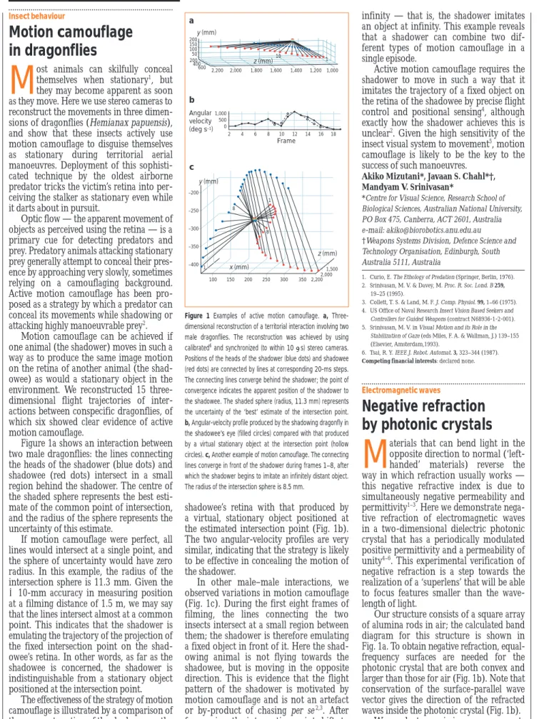
shadowee’s retina with that produced by a virtual, stationary object positioned at the estimated intersection point (Fig. 1b). The two angular-velocity profiles are very similar, indicating that the strategy is likely to be effective in concealing the motion of the shadower.
In other male–male interactions, we observed variations in motion camouflage (Fig. 1c). During the first eight frames of filming, the lines connecting the two insects intersect at a small region between them; the shadower is therefore emulating a fixed object in front of it. Here the shad-owing animal is not flying towards the shadowee, but is moving in the opposite direction. This is evidence that the flight pattern of the shadower is motivated by motion camouflage and is not an artefact or by-product of chasing per se2,3. After
frame nine, the intersection point shifts to
infinity — that is, the shadower imitates an object at infinity. This example reveals that a shadower can combine two dif-ferent types of motion camouflage in a single episode.
Active motion camouflage requires the shadower to move in such a way that it imitates the trajectory of a fixed object on the retina of the shadowee by precise flight control and positional sensing4, although
exactly how the shadower achieves this is unclear2. Given the high sensitivity of the
insect visual system to movement5, motion
camouflage is likely to be the key to the success of such manoeuvres.
Akiko Mizutani*, Javaan S. Chahl*†, Mandyam V. Srinivasan*
*Centre for Visual Science, Research School of Biological Sciences, Australian National University, PO Box 475, Canberra, ACT 2601, Australia e-mail: [email protected] †Weapons Systems Division, Defence Science and Technology Organisation, Edinburgh, South Australia 5111, Australia
1. Curio, E. The Ethology of Predation (Springer, Berlin, 1976). 2. Srinivasan, M. V. & Davey, M. Proc. R. Soc. Lond. B 259,
19–25 (1995).
3. Collett, T. S. & Land, M. F. J. Comp. Physiol. 99, 1–66 (1975). 4. US Office of Naval Research Insect Vision Based Seekers and
Controllers for Guided Weapons (contract N68936-1-2-001). 5. Srinivasan, M. V. in Visual Motion and its Role in the
Stabilization of Gaze (eds Miles, F. A. & Wallman, J.) 139–155 (Elsevier, Amsterdam,1993).
6. Tsai, R. Y. IEEE J. Robot. Automat. 3, 323–344 (1987).
Competing financial interests: declared none.
Electromagnetic waves
Negative refraction
by photonic crystals
M
aterials that can bend light in theopposite direction to normal (‘left-handed’ materials) reverse the way in which refraction usually works — this negative refractive index is due to simultaneously negative permeability and permittivity1–3. Here we demonstrate
nega-tive refraction of electromagnetic waves in a two-dimensional dielectric photonic crystal that has a periodically modulated positive permittivity and a permeability of unity4–6. This experimental verification of
negative refraction is a step towards the realization of a ‘superlens’ that will be able to focus features smaller than the wave-length of light.
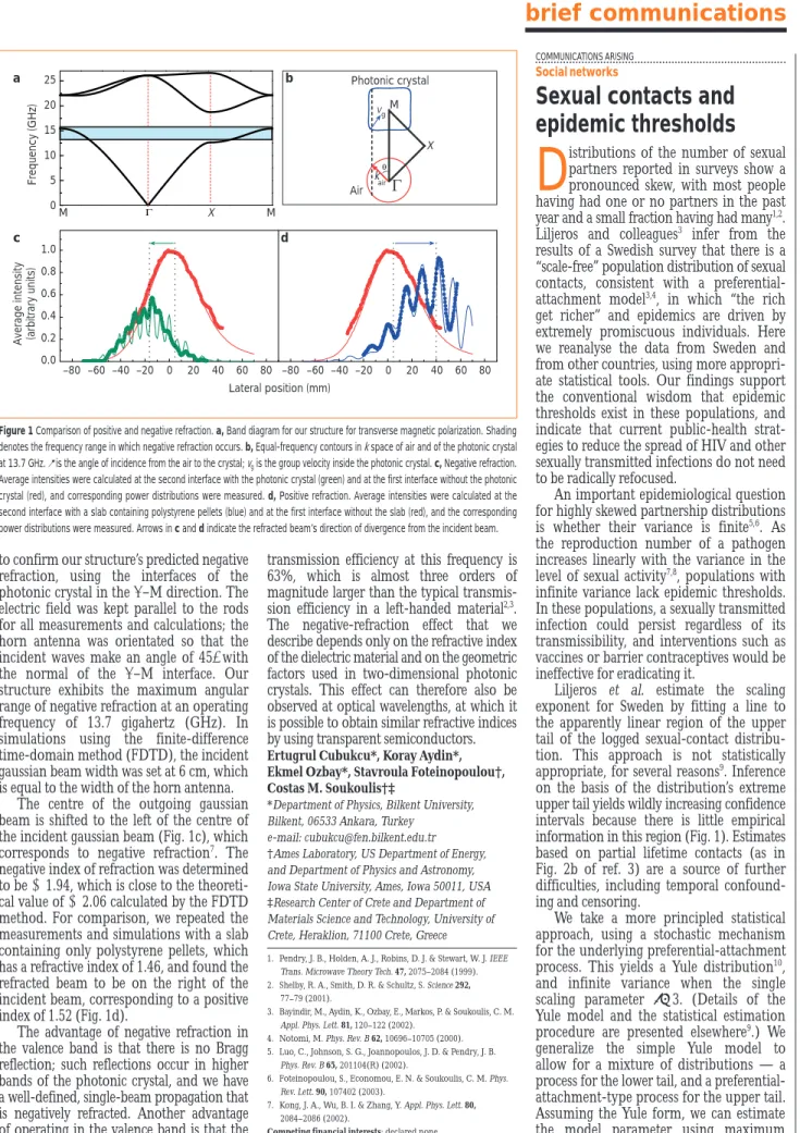
Our structure consists of a square array of alumina rods in air; the calculated band diagram for this structure is shown in Fig. 1a. To obtain negative refraction, equal-frequency surfaces are needed for the photonic crystal that are both convex and larger than those for air (Fig. 1b). Note that conservation of the surface-parallel wave vector gives the direction of the refracted waves inside the photonic crystal (Fig. 1b). We made transmission measurements
604 NATURE|VOL 423|5 JUNE 2003|www.nature.com/nature
Insect behaviour
Motion camouflage
in dragonflies
M
ost animals can skilfully conceal themselves when stationary1, butthey may become apparent as soon as they move. Here we use stereo cameras to reconstruct the movements in three dimen-sions of dragonflies (Hemianax papuensis), and show that these insects actively use motion camouflage to disguise themselves as stationary during territorial aerial manoeuvres. Deployment of this sophisti-cated technique by the oldest airborne predator tricks the victim’s retina into per-ceiving the stalker as stationary even while it darts about in pursuit.
Optic flow — the apparent movement of objects as perceived using the retina — is a primary cue for detecting predators and prey. Predatory animals attacking stationary prey generally attempt to conceal their pres-ence by approaching very slowly, sometimes relying on a camouflaging background. Active motion camouflage has been pro-posed as a strategy by which a predator can conceal its movements while shadowing or attacking highly manoeuvrable prey2.
Motion camouflage can be achieved if one animal (the shadower) moves in such a way as to produce the same image motion on the retina of another animal (the shad-owee) as would a stationary object in the environment. We reconstructed 15 three-dimensional flight trajectories of inter-actions between conspecific dragonflies, of which six showed clear evidence of active motion camouflage.
Figure 1a shows an interaction between two male dragonflies: the lines connecting the heads of the shadower (blue dots) and shadowee (red dots) intersect in a small region behind the shadower. The centre of the shaded sphere represents the best esti-mate of the common point of intersection, and the radius of the sphere represents the uncertainty of this estimate.
If motion camouflage were perfect, all lines would intersect at a single point, and the sphere of uncertainty would have zero radius. In this example, the radius of the intersection sphere is 11.3 mm. Given the 510-mm accuracy in measuring position at a filming distance of 1.5 m, we may say that the lines intersect almost at a common point. This indicates that the shadower is emulating the trajectory of the projection of the fixed intersection point on the shad-owee’s retina. In other words, as far as the shadowee is concerned, the shadower is indistinguishable from a stationary object positioned at the intersection point.
The effectiveness of the strategy of motion camouflage is illustrated by a comparison of the apparent motion of the shadower on the
brief communications
200 y (mm) z (mm) 200 400 600 2,200 2,000 1,800 1,600 1,400 1,200 1,000 150 100 50 10 1 a b c 2 4 6 8 10 12 14 16 18 1,000 500 0 Frame Angular velocity (deg s–1) –200 –250 –300 –350 –400 100 1 8 1 8 150 200 250 300 350 2,200 2,000 1,500 z (mm) x (mm) y (mm)Figure 1 Examples of active motion camouflage. a,
Three-dimensional reconstruction of a territorial interaction involving two male dragonflies. The reconstruction was achieved by using
calibrated6and synchronized (to within 10 ms) stereo cameras.
Positions of the heads of the shadower (blue dots) and shadowee (red dots) are connected by lines at corresponding 20-ms steps. The connecting lines converge behind the shadower; the point of convergence indicates the apparent position of the shadower to the shadowee. The shaded sphere (radius, 11.3 mm) represents the uncertainty of the ‘best’ estimate of the intersection point.
b, Angular-velocity profile produced by the shadowing dragonfly in
the shadowee’s eye (filled circles) compared with that produced by a virtual stationary object at the intersection point (hollow circles). c, Another example of motion camouflage. The connecting lines converge in front of the shadower during frames 1–8, after which the shadower begins to imitate an infinitely distant object. The radius of the intersection sphere is 8.5 mm.
to confirm our structure’s predicted negative refraction, using the interfaces of the photonic crystal in the G–M direction. The electric field was kept parallel to the rods for all measurements and calculations; the horn antenna was orientated so that the incident waves make an angle of 457 with the normal of the G–M interface. Our structure exhibits the maximum angular range of negative refraction at an operating frequency of 13.7 gigahertz (GHz). In simulations using the finite-difference time-domain method (FDTD), the incident gaussian beam width was set at 6 cm, which is equal to the width of the horn antenna.
The centre of the outgoing gaussian beam is shifted to the left of the centre of the incident gaussian beam (Fig. 1c), which corresponds to negative refraction7. The
negative index of refraction was determined to be 11.94, which is close to the theoreti-cal value of 12.06 theoreti-calculated by the FDTD method. For comparison, we repeated the measurements and simulations with a slab containing only polystyrene pellets, which has a refractive index of 1.46, and found the refracted beam to be on the right of the incident beam, corresponding to a positive index of 1.52 (Fig. 1d).
The advantage of negative refraction in the valence band is that there is no Bragg reflection; such reflections occur in higher bands of the photonic crystal, and we have a well-defined, single-beam propagation that is negatively refracted. Another advantage of operating in the valence band is that the
transmission efficiency at this frequency is 63%, which is almost three orders of magnitude larger than the typical transmis-sion efficiency in a left-handed material2,3.
The negative-refraction effect that we describe depends only on the refractive index of the dielectric material and on the geometric factors used in two-dimensional photonic crystals. This effect can therefore also be observed at optical wavelengths, at which it is possible to obtain similar refractive indices by using transparent semiconductors. Ertugrul Cubukcu*, Koray Aydin*, Ekmel Ozbay*, Stavroula Foteinopoulou†, Costas M. Soukoulis†‡
*Department of Physics, Bilkent University, Bilkent, 06533 Ankara, Turkey
e-mail: [email protected] †Ames Laboratory, US Department of Energy, and Department of Physics and Astronomy, Iowa State University, Ames, Iowa 50011, USA ‡Research Center of Crete and Department of Materials Science and Technology, University of Crete, Heraklion, 71100 Crete, Greece
1. Pendry, J. B., Holden, A. J., Robins, D. J. & Stewart, W. J. IEEE Trans. Microwave Theory Tech. 47, 2075–2084 (1999). 2. Shelby, R. A., Smith, D. R. & Schultz, S. Science 292,
77–79 (2001).
3. Bayindir, M., Aydin, K., Ozbay, E., Markos, P. & Soukoulis, C. M. Appl. Phys. Lett. 81, 120–122 (2002).
4. Notomi, M. Phys. Rev. B 62, 10696–10705 (2000). 5. Luo, C., Johnson, S. G., Joannopoulos, J. D. & Pendry, J. B.
Phys. Rev. B 65, 201104(R) (2002).
6. Foteinopoulou, S., Economou, E. N. & Soukoulis, C. M. Phys. Rev. Lett. 90, 107402 (2003).
7. Kong, J. A., Wu, B. I. & Zhang, Y. Appl. Phys. Lett. 80, 2084–2086 (2002).
Competing financial interests: declared none.
brief communications
NATURE|VOL 423|5 JUNE 2003|www.nature.com/nature 605
COMMUNICATIONS ARISING
Social networks
Sexual contacts and
epidemic thresholds
D
istributions of the number of sexualpartners reported in surveys show a pronounced skew, with most people having had one or no partners in the past year and a small fraction having had many1,2.
Liljeros and colleagues3 infer from the
results of a Swedish survey that there is a “scale-free” population distribution of sexual contacts, consistent with a preferential-attachment model3,4, in which “the rich
get richer” and epidemics are driven by extremely promiscuous individuals. Here we reanalyse the data from Sweden and from other countries, using more appropri-ate statistical tools. Our findings support the conventional wisdom that epidemic thresholds exist in these populations, and indicate that current public-health strat-egies to reduce the spread of HIV and other sexually transmitted infections do not need to be radically refocused.
An important epidemiological question for highly skewed partnership distributions is whether their variance is finite5,6. As
the reproduction number of a pathogen increases linearly with the variance in the level of sexual activity7,8, populations with
infinite variance lack epidemic thresholds. In these populations, a sexually transmitted infection could persist regardless of its transmissibility, and interventions such as vaccines or barrier contraceptives would be ineffective for eradicating it.
Liljeros et al. estimate the scaling exponent for Sweden by fitting a line to the apparently linear region of the upper tail of the logged sexual-contact distribu-tion. This approach is not statistically appropriate, for several reasons9. Inference
on the basis of the distribution’s extreme upper tail yields wildly increasing confidence intervals because there is little empirical information in this region (Fig. 1). Estimates based on partial lifetime contacts (as in Fig. 2b of ref. 3) are a source of further difficulties, including temporal confound-ing and censorconfound-ing.
We take a more principled statistical approach, using a stochastic mechanism for the underlying preferential-attachment process. This yields a Yule distribution10,
and infinite variance when the single scaling parameter r 3. (Details of the Yule model and the statistical estimation procedure are presented elsewhere9.) We
generalize the simple Yule model to allow for a mixture of distributions — a process for the lower tail, and a preferential-attachment-type process for the upper tail. Assuming the Yule form, we can estimate the model parameter using maximum
Photonic crystal M Vg 25 20 15 10 5 0 1.0 0.8 0.6 0.4 0.2 0.0 M X M Frequency (GHz)
Average intensity (arbitrary units)
–80 –60 –40 –20 0 20 40 60 80 –80 –60 –40 –20 0 20 40 60 80 Lateral position (mm) c d b a X Air air k
Figure 1 Comparison of positive and negative refraction. a, Band diagram for our structure for transverse magnetic polarization. Shading
denotes the frequency range in which negative refraction occurs. b, Equal-frequency contours in kspace of air and of the photonic crystal
at 13.7 GHz. uis the angle of incidence from the air to the crystal; vgis the group velocity inside the photonic crystal. c, Negative refraction.
Average intensities were calculated at the second interface with the photonic crystal (green) and at the first interface without the photonic crystal (red), and corresponding power distributions were measured. d, Positive refraction. Average intensities were calculated at the second interface with a slab containing polystyrene pellets (blue) and at the first interface without the slab (red), and the corresponding power distributions were measured. Arrows in c and d indicate the refracted beam’s direction of divergence from the incident beam.