immediate
Abstract This study addresses the issue of silhouette extraction of a street, and proposes two novel approaches to overcome this problem. The first, namely hybrid-stitching, considers the silhouette extraction as an image stitching problem and aims to use 2D street view images. The algorithm used in this method integrates a new composition technique into a conventional image stitching pipeline. The developed software using the proposed hybrid approach results in better stitching performances when compared with the popular stitching tools in the literature. Despite the results of the proposed method are better than the state-of-the-art image stitching techniques in many cases, they are not reliable enough to handle all of the street view image sets. Accordingly, a second solution has been proposed, including 3D location information, namely, 3D Silhouette Extraction Pipeline. The pipeline involves several techniques and post-processing steps to handle both the transformation and projection of the obtained point cloud, and the elimination of misleading location information. The results reveal that compared with the 2D solutions, the proposed algorithm is very effective and more reliable in silhouette extraction of a street, which is critical in urban transformation and environmental protection.
Keywords Silhouette Extraction, Image Stitching, Street Views, Urban Transformation
1. Introduction
Recent researches reveal that developing countries implement urban transformation without considering environmental aesthetics. Within the scope of systematic monitoring of urban regeneration, the whole aspects and line art silhouettes of streets are primarily required. The silhouette is the simplest form of line art and can be utilised in technical illustrations and architectural design [1]. However, in the cases that this paper addresses, a silhouette of a street is identified as a coloured image that contains the information from all of the objects of interest (buildings and all of the objects that affect the configuration of the street), or in other words, expresses all the aspects of that street.
Not only the line art version silhouettes but also coloured street aspects are being used and performing measurements is also required for this urban regeneration process. At the present time, these silhouettes are extracted from street view images by municipal officials and
ARTICLE
1 Netcad, Turkey
2 Computer Engineering Department, Gazi University, Turkey 3 Computer Engineering Department, Ankara University, Turkey 4 Computer Engineering Department, Baskent University, Turkey 5 Computer Engineering Department, Hacettepe University, Turkey * Corresponding author E-mail: [email protected]
Received 12 Mar 2014; Accepted 04 Jun 2014 DOI: 10.5772/58740
∂ 2014 The Author(s). Licensee InTech. This is an open access article distributed under the terms of the Creative Commons Attribution License (http://creativecommons.org/licenses/by/3.0), which permits unrestricted use, distribution, and reproduction in any medium, provided the original work is properly cited.
Begüm Mutlu
1, Murat Hacıömeroğlu
2,
Mehmet Serdar Guzel
3,*, Mehmet Dikmen
4and Hayri Sever
5Silhouette Extraction
from Street View Images
Regular Paper
Figure 1.Example of street silhouette from Edirne, Turkey
employees, the experts of urban planning and architects manually. However, it is a time consuming and labour intensive process. Therefore, silhouette extraction problem is considered as an image stitching problem in this study and an accurate silhouette extraction framework both from street view images and the 3D location files is proposed. Image stitching is one of the most challenging issues in computer vision field, which, in essence, aims to combine multiple images with overlapping fields of view to yield a high-resolution image. Despite the complexity of this process, it has drawn the attention of researchers from different backgrounds. The main idea concerning the image stitching problem is to employ a simple camera to take a few photographs, and being able to stitch these pictures using image processing methods to yield a panoramic image. Technically, in image stitching, all the images captured are warped into a reference sphere or cylinder and from which the entire field of view can be obtained. Several new ideas were proposed in the literature; first of those stitches video frames directly from MPEG data, which involves estimation of the global
motion from the MPEG motion vectors [2]. Having
obtained satisfactory results in image stitching, a robust transition from one image to another is required, where both structure and intensity should be aligned within the overlapped area [3]. One of the main constraints in photo stitching is to take images from the same reference point. However, modelling an ordinary street view may involve changing the reference point that a sequence of images are taken at successive time intervals. For instance, a vehicle equipped with multiple cameras moves towards a street and captures photos for each five meters along the way. Silhouette extraction of the given street (see Figure 1 as an example silhouette) is a difficult problem and should be considered and analysed in a detailed way. This paper proposes two novel approaches for the given problem; the first of those employs only 2D data for stitching so that the photos are taken by periodically
shifting (moving) cameras. This technique resembles
stitching pipeline technique, which can be seen in [4]. However, there is a vital difference between the original technique and the proposed approach (see Section 3); the conventional method works with images taken from one specific reference point, which does not fit the scenario introduced in this study. Alternatively, in the second approach examined in Section 4.2, depth data taken from a stereo camera system has been integrated into the stitching process. It is observed that this approach produces better performance results compared with its 2D counterpart. Several critical scenarios are applied to the popular commercial and non-commercial image stitching tools in order to have a robust comparison between the tools used in the corresponding field and the methods proposed in this study. All of the comparison results and
the advantages of the proposed methods over the existing methods are presented.
The paper is organised as follows: Section 2 is a review of the relevant literature which forms the foundation of this study. Section 3 addresses the proposed 2D street view image based stitching technique and its adaption to the silhouette extraction process. Section 4, on the other hand, introduces a novel technique employing 3D location information for image registration problem. Finally, Section 5 concludes the paper.
2. Related Work
People have always been fascinated about capturing the entire view of scenes. Image stitching is one of the most popular methods used in this field, in which the sequence of digital images is used to form a single image that portrays a larger angle of view. Image stitching algorithms, in essence, use alignment estimates produced by image registration algorithms and blend the images in a unified manner. There have been significant efforts in large scale reconstruction in the last few years aiming at urban regeneration issue. Some of these use aerial images [5][6]. Here, research on urban reconstruction from ground-based imagery is discussed as it is closely related to what is proposed in this work. Automatic stitching falls into two categories: direct and feature based. Direct methods use all of the available image data and hence can provide accurate registration. However, they require a close initialisation [7]. Alternatively, feature based methods do not need initialisation, but the conventional feature based methods are not able to provide reliable matching due to the shortage of invariance properties [8].
Brown and Lowe [4] expressed stitching as a multi-image matching problem, and employed local features to find matches between images that the method developed is insensitive to orientation, scale and illumination of the input images. Mills and Dudek [9] introduced a new technique to stitch automatically and blend images with dynamic elements, which partially solves the problems of moving objects, small parallax and illumination changes. The technique, basically, employs heuristic seam selection in intensity and gradient domains in order to determine corresponding pixels from images and then blends them
smoothly. Alternatively, Tang, Wong and Heng [10]
introduced an application for live panoramic video stitched together from live inputs from multiple cameras. Their implementation of this system was divided into offline and online phases. In the offline phase, sample videos were taken and then used to obtain parameters for stitching each of the frames (this worked because once the online phase began, the cameras were stationary). In the online phase, the videos were synchronised using time stamps and then stitched together using the previously calculated parameters.
Figure 2. An illustration of street view image acquisition technique where direction of the motion is d
Guerrero [11] proposed the comparison of three image processing algorithms namely: FAST [12], SIFT [13] and SURF [14]. The study is particularly useful since it presents both feature detection and matching success rates. In addition these algorithms are utilized in several studies both in image stitching problem [4][15][16][17] and other research areas [18].
Jia and Tang [3], on the other hand, sought to achieve seamless image stitching based on structure deformation and propagation for overall consistency in image structure and intensity. In a recent patent case [19], a method for generating a continuum of image data was provided. The continuum can include image data representing a street level view of a geographic area. The image data can be captured at multiple disparate points along another continuum. Each continuum of image data can include a ribbon of data representing the geographic area. In some examples, image data can be simultaneously captured, which represents multiple continuums of image data. Furthermore, there are three popular applications, which have been widely used for the image stitching problem. One of them is Microsoft Image Composite Editor [15],
a commercial software. The tool is an advanced
panoramic image stitcher using overlapping photographs of a scene shot from a single camera position results in high-resolution panorama that seamlessly combines the original images. The second is the Hugin tool which is a cross-platform open source panorama photo stitching and HDR merging program; the details of the software can be seen in [16]. And the final application, Autostitch [17], is a tool that employs collections of images to automatically matches between images using the SIFT [13] algorithm. 3. Silhouette Extraction by Using 2D Street Views
3.1. 2D Data
This section addresses how to examine a street view image from an existing dataset. Each street view consists of five images, which are right, left, upper, front and back images. These images are obtained by using frequently
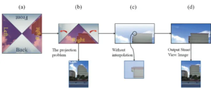
Figure 3. Upper image composition of right/left street view images. (a) A sample right upper image with four identical parts. (b) The projection problem and the transformation of the corresponding part of the upper image. (c) The transformation result without interpolation. (d) Interpolation result and the final right street view image.
moving cameras, illustrated in Figure 2. This kind of street view image acquisition technique, detailed in [20], is called acquisition by camera translation.
As previously mentioned, in the proposed work, street view images are primarily used for 2D silhouette
extraction problem. Right, left and sky images are
captured by using right, left and centred cameras respectively. This operation results in obtaining different aspects of the buildings, which are the main objects of interest in the addressed cases. It is clear that right or/and left parts of images include the most valuable data for stitching process. However, there is an exceptional situation in which the objects of interest in images are too long to fit in a single street view image. To overcome this problem, right and/or left images may be composited with upper ones in order to obtain the whole street view image as seen in Figure 3.
Direct composition of upper images with associated lateral images has a serious projection problem. This is because an upper image contains information from other directions (right, left, front, back images) as well. Accordingly, a simple solution has been proposed to overcome this
problem. The technique developed crops the upper
image into four identical triangles (shown in Figure 3(a)). Afterwards, a simple but efficient transformation is applied to the left and right triangle images extracted from the upper image as seen in Figure 3(b). The transformation method essentially transforms any pixel, p(x, y), in the current image into a new point p (x , y)by using 1 where W is the width of the input street view image.
w=W
2,
x = (w∗ (x−w) y ) +w
(1) After the transformation is completed, there appear some pixels without colour information as seen in Figure 3(c). An interpolation step is applied to handle this problem. The interpolation technique proposed for any pixel p without colour information is shown in 2 where p is
the new colour value of the pixel in question, ppre is
the predecessor and psuc is the successor of the pixel p with colour information. In addition, dpre and dsuc
indicate the distance between the corresponding pixel and its predecessor and successor respectively. This
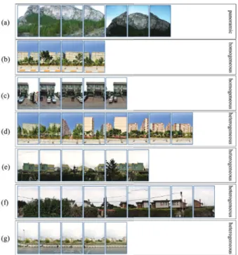
Figure 4.Sample street view image sets
calculation is applied for each colour component (R, G, B) of corresponding empty pixels (see Figure 3(d)). Finally, modified left/right upper images are composited with the corresponding left/right image to generate the whole street view image.
p = ppre∗dpre+psuc∗dsuc
dpre+dsuc (2) 3.2. Methods for 2D Silhouette Extraction
Since our silhouette, determination problem is addressed as an image stitching problem. One of the well-known stitching pipelines is implemented, which is detailed
in [4]. However, there is a significant difference
between the cases that existing techniques try to solve [4][15][16][17] and the case that has been discussed in this work. Conventional stitching solutions are focused on the stitching of panoramic images (see Figure 4(a)) that are taken from one specific location, while the street views used in this study (Figure 4(b)(c)(d)(e)(f)(g)) are taken by periodically shifting (moving) cameras. Having obtained the images from moving cameras is an important challenge, detailed in [20]. Preliminary experiments reveal that existing image stitching solutions [4][15][16][17] are not able to achieve acceptable results while dealing with the corresponding problem (shown in Figure 9). Accordingly, a hybrid-stitching algorithm has been introduced in order to deal with the given issue by mainly integrating a new composition technique into the conventional stitching technique [4].
The preliminary tests conducted during this work revealed that popular stitching techniques surprisingly are able to produce good results when both objects of interest are far away from the camera and the image data set is small because the camera translation is not much, in relative terms, and the overlapping area is large enough. It is proved that having a large number of matched
Figure 5. An illustration of feature filter. (a) Intermediate result from five street views. (b) A new street view image to be stitched with the intermediate result. (c) The stitching result.
points enhances the quality of image stitching process [20]. Essentially, the main issue behind previously mentioned results is all related with having more overlapping areas between subsequent images. However, when the number of query images increases, current techniques tend to fail, because the overlapped area between the street view images starts to shrink due to the increment of camera transition. In order to enhance the obtained results, a new stitching flow approach, called chain stitching, has been introduced by using the information, so that the street view images used in this work are sequential.
According to chain stitching approach, each image is expressed as a ring in the whole chain, where each ring is stitched with its successor. For instance, after stitching the first and the second images, the output image obtained from this process is stitched with the third and so on. However, there occur some unexpected problems during this process. This is because during the chain-stitching flow, the size of intermediate stitching result starts to enlarge, which consumes much process time to detect precise key-points and raises the number of irrelevant matches between key-points. Therefore, a simple filtering technique has been applied to the whole image in order to eliminate the key-points which are useless for the stitching process.
Figure 5 illustrates the given feature filtering procedure. When considering to stitch the sixth image into an intermediate stitching result of the first five images, the filtering technique aims to match only the overlapped parts of the intermediate image with the new image and those which do not provide the given assumption are eliminated. There is also a constraint with this filtering process, meaning that the size of the overlapped part can be at most the size of an input image. Thus, the matching process is only applied to the key-points that are located on the red areas, as shown in the corresponding image. Having a complete silhouette of a street requires employing all street view images without any exception. Satisfying this necessity makes it possible to generate a continuous result. However, there may occur some unexpected cases that the conventional stitching [4] pipeline tends to fail, such as when the algorithm is not able to stitch the intermediate result with its
successor. This case prevents the continuity of the
silhouette construction procedure. For this reason, an alternative composition technique is introduced, which is triggered when the conventional method [4] fails to complete the stitching process. The technique primarily tries to find the best match by applying a new match filter
mechanism. Afterwards, once the best match is estimated, the corresponding image is superposed on its successor by using this match point (seen in Figure 6). However, determining the best match becomes another problem to be addressed, and the following paragraph details the solution to this problem.
Figure 6.Match filter constraints and alternative composition (a) using the topmost match. (b) using any good match.
Algorithm 1: Hybrid-stitching algorithm
Data:ImageList (Input Image List) Result:P (Stitching Result)
Declare a stack called S; Declare a stack called NS; Push the first image to S; Push the second image to S;
whilethere is no more image to stitch in ImageList do imageRight = POP(S);
imageLe f t = POP(S);
P = Stitch(imageLe f t, imageRight) [4];
ifP is not null then ifNS is empty then Predecessor = imageLe f t; Previous = imageRight; end else Successor = imageRight; Push Previous to NS;
Intermediate = Composite(NS) (Sec. 3.2); P = Stitch(Predecessor, Intermediate) [4]; P = Stitch(P, Successor) [4]; Clear NS; end Push P to S; end else Push imageRight to NS; Push imageRight to S; end
Push the next image in ImageList (if exist) to S;
end returnP;
Determining the best match mainly concerns developing a match filter mechanism by accounting for the fact that street view images used in this study are sequentially captured and the camera translates on a plane with minimum or no rotation among the streets. According to preliminary test results, two constraints are found to be applicable for the cases examined here. The first constraint
assumes that the x component of the matched key-point of the second image is greater than the x component of the matched key-point of the first image, as illustrated in Figure 6. The second constraint, on the other hand, focuses on match filter mechanism based on the y component of images. This constraint actually postulates that the y components of matched key-points must be close (if not the same) to each other. Key points not satisfying these two constraints are identified as weak key-points. Once the match filtering process has been applied, weak key-points are eliminated and a subset with the minimum matching distance is shelled from the remaining set. The matched key-points which are both located at the topmost part of their corresponding images are selected from this subset as the best match. The performance comparison between the selection methods, which are using the topmost and one of the lowest matched points respectively, are illustrated in Figure 6(a) and 6(b). Overall, the results verify that the selection of the matched key-points in the topmost location offers more reliable stitching results even if the lower parts in the result seem distorted.
3.3. Hybrid-Stitching Model
In order to overcome the silhouette extraction problem, a new hybrid-stitching model (given in Algorithm 1) which involves both conventional image stitching technique and the composition technique (see Section 3.2) is introduced in this study. The algorithm tries to stitch the street view images by applying alternative composition technique where the conventional approach fails. When two images fail to be stitched by the conventional algorithm, the hybrid-stitching model searches for the subsequent images by skipping those failed images with the composition technique. The search stops when a successfully stitched pair is found. Then, an intermediate result is obtained by stitching those failed images with the composition technique. Finally, this result is stitched first with its predecessor and then its successor by conventional algorithm to form the output. Algorithm iterates these steps by stitching this output with the remaining images until the final output is obtained.
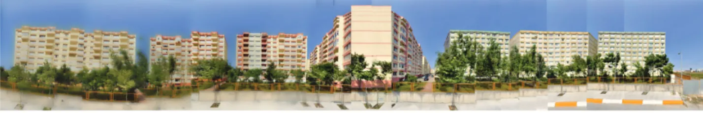
Figure 8. An example of street silhouette produced from thirty-two street view images by using hybrid-stitching algorithm (Istanbul, Turkey)
Figure 7 illustrates an example of the corresponding stitching process in which it is assumed that there exist
n sequential street view images. Initially, the first three images are found to be stitched in chain by the conventional technique until it fails with the fourth image. At this stage, Previous contains the last successfully stitched image (i.e., the third) and Predecessor holds the stitching result without this image. Next, starting from the fourth, all images failed in stitching are pushed in to the stack NS until the fifth and sixth (i.e., Successor) images are stitched by the conventional technique. Then, images in the NS including Previous are stitched by the composition technique to form an intermediate result. This result is stitched with its Predecessor and Successor by the conventional technique to obtain the output which is pushed again to S to iterate all these steps with the
remaining images in the list. An example silhouette
produced by hybrid-stitching algorithm can be seen in Figure 8.
3.4. Results for Hybrid-Stitching Approach
The 2D street view images used in this study have both homogeneous (see Figure 4(b)) and heterogeneous (see Figure 4(c)(d)(e)(f)) structures. A homogeneous image set can be defined as a group of images whose objects of interest are on the same plane that is as parallel as possible to the direction of camera transition. Briefly, the distance between camera and each object of interest is stable. This parallelism is important because of possible scale problems.
In the corresponding street view repository, homogeneous image sets are in a minority. This is because, even a great number of homogeneous views have many decomposer (resolver) objects such as trees, vehicles, fences etc. However, in these kinds of views, the essential part of the objects of interest can be utilised to obtain consistent stitching result. Alternatively, if the objects of interest remain in the background owing to the aforementioned decomposers or if more than one object of interest have different distance values with respect to the camera, these views are labelled as heterogeneous.
In order to evaluate the performance results of the proposed image stitching flow, the technique is primarily compared with the popular stitching tools [4][15][16][17] based on the same street view image database. Notably, as opposed to the proposed stitching flow approach, these tools do not have the capability of extracting a complete silhouette of a street. This is because; they all focus on solving the panoramic image stitching problem, involving the images that are taken from one specific location as
Set (*) Autostitch Hugin MS ICE Hybrid-Stitching
a 7/7 7/7 7/7 7/7 b 2/4 2/4 2/4 4/4 c 0/5 5/5 3/5 5/5 d 2/8 0/8 4/8 8/8 e 2/6 2/6 2/6 6/6 f 0/9 1/9 0/9 9/9 g 0/5 5/5 5/5 5/5
(*): Image sets as illustrated in Figure 4
Table 1.Comparison table of existing stitching tools
Figure 9. Comparison of existing image stitching tools for the given street view image sets
shown in Figure 4(a). At this point, it is critical to mention that these image stitching tools can have good results when the camera moves in short distance or the objects of interest are far enough to overcome this movement effect. However, as the camera movement increases, they cannot guarantee finding a sufficient number of good matching points and tend to fail in silhouette extraction process. Besides, they do not have the information; the street view images are gathered in a correct order and the matching features are located on a special area in the complete image. Overall, the proposed hybrid-stitching flow can achieve better results, compared with the corresponding popular stitching tools, as shown in Figure 9.
In Figure 9, the image sets (4) used are not enough of a whole silhouette. However, the tools used for comparison often fail to stitch a large number of images. Therefore, to be able to compare the proposed technique with the existing stitching tools, the experiments are applied on
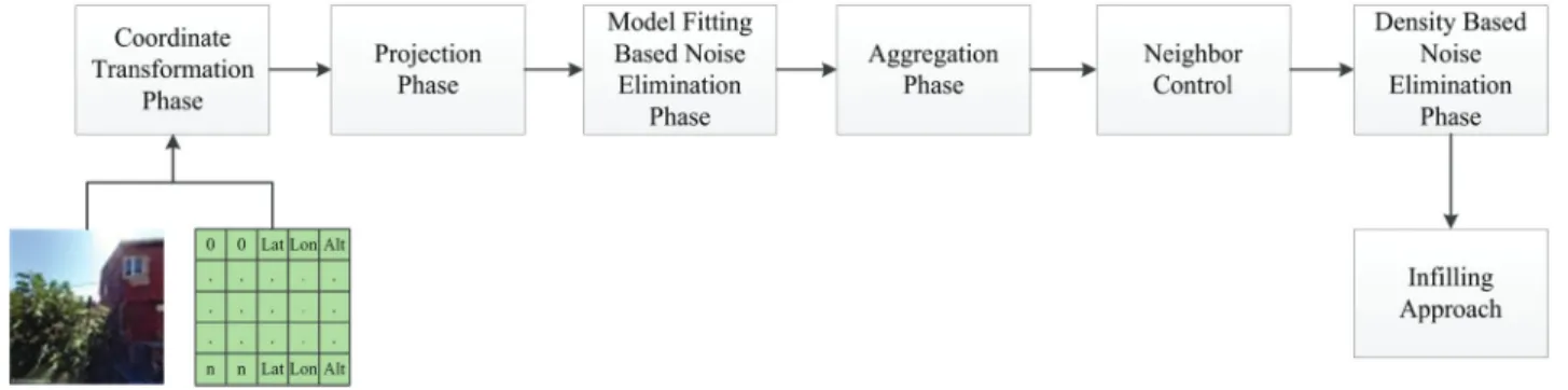
Figure 10.3D location based silhouette extraction pipeline
such sets. Nevertheless, it should be noted that, a typical street is as large as the street shown in Figure 8.
In Table 1, a numerical comparison of each image stitching tool is illustrated. The image sets in this comparison are the same as the image sets in Figure 4 and 9, and the ratios on the corresponding table expresses the ratio between the number of images successfully stitched and the total number of images in the image set. The results prove that the proposed hybrid-stitching technique results in better stitching performance for the given scenarios. It can also be inferred that the hybrid-stitching technique aims to preserve the data from all objects of interest so as to obtain a continuum silhouette.
4. Silhouette Extraction by Using 3D Street Views
Despite the fact hybrid-stitching algorithm generates acceptable results, it tends to fail in several scenarios, especially with the heterogeneous image sets, which are discussed in Section 3.4. Accordingly, a new 3D location based silhouette extraction algorithm has been introduced and detailed in the following sections.
4.1. 3D Data
In this section, a 3D location based solution for the silhouette extraction problem is proposed by using street view images and the spherical coordinates (as latitude, longitude, altitude) for each pixel on these images. Nevertheless, it is detected that this 3D information could be inaccurate for some pixels, such as clouds, trees and shadows intersecting with the objects of interest even with the buildings. In addition, if the camera and the object of interest is far away from each other, the location information of the corresponding object may become unreliable. The influence of the distance parameter is illustrated in Figure 11, proving the given hypothesis. While Figure 11(a) demonstrates the source image and the corresponding image projected on to the 2D camera plane, Figure 11(b) demonstrates the matches between the objects from the source and the projected images. Accordingly, it is observed that the reliability of the results decreases as the distance from objects to camera increases.
Another parameter affecting the characteristic of data is the horizontal angle between the normal vector of the camera plane and any object of interest, especially in such cases that the object of interest and the camera are
located far away from each other. Preliminary tests have been conducted by importing raw location data and it is revealed that once the value of this angle is extended, the corrupted data increases dramatically.
Consequently, these types of inappropriate data are considered as outliers, and while the silhouette extraction pipeline is proceeding, further elimination techniques are employed to avoid these outliers as examined in Section 4.2.3. Afterwards, the point cloud obtained is transferred into an output image, followed by applying a number of post-processing steps (see Section 4.2.5 and 4.2.6). Finally, the gaps on the output image are filled by a simple but efficient algorithm, detailed in Section 4.2.7.
4.2. 3D Silhouette Extraction Pipeline
As mentioned previously, a 3D location based silhouette extraction pipeline is created (see Figure 10) by using street view images and the spherical coordinates of each pixel on these images.
In this paper, the term, camera is referred to determine the camera position for each street view image and it is assumed that the number of cameras and the number of street view images are equal. Despite having only
Figure 11. An illustration indicating the need for the distance based elimination. (a) Projected point cloud of the given image. (b) Clusters in the projected point cloud corresponding to each object of interest for the source image.
Figure 12. Point projection into camera plane. (a)Identification of the objects. (b)Projection into camera plane. (c)Rotation of camera plane by an angle α.
Figure 13. Implementation of model fitting elimination approach on a 100x100 pixels street view image
one shifting camera to acquire these images (right or left street view images individually) for the real world, this appellation is required in order to provide a more definable and perceptible concept. Additionally, the camera located at the beginning of the street is the starting camera and the camera that is located at the end of the street is the end camera (shown in Figure 12).
Figure 14.Implementation results for the street view data, given in Figure 13
Figure 15.Implementation results of model fitting elimination
4.2.1. Coordinate Transformation Phase
First, a coordinate transformation from spherical
coordinate system to Universal Transverse Mercator
(UTM) Coordinate System is performed. This step
is mandatory since the latitude and longitude are in degrees while the altitude is measured in metres. In this transformation step, such points whose distance from the corresponding camera is more than a specified threshold, are eliminated. The reason for this restriction is not only to eliminate information obtained from irrelevant street views (such as a street behind the current street), but also to disregard the incorrect location information. Essentially, once any object is far away from the camera, it becomes harder to estimate the spherical location information of the corresponding object, as discussed in Section 4.1
4.2.2. Projection Phase
Once the coordinate transformation has completed, the projection phase is started. Firstly, a camera plane is created with the vector from the starting camera to the end camera and the altitude vector. The point cloud acquired from the objects is projected to this plane as seen in Figure 12(b). Finally, the aforementioned camera plane and projected points are formed in 3D space. Therefore, to obtain a complete view in 2D, the plane with the projected points is rotated with an angle α (the horizontal angle between the camera plane and the x axis (Easting) of UTM coordinate system) to lean the plane into the x axis (see Figure 12(c)).
4.2.3. Model Fitting Based Noise Elimination Phase
Although a distance based elimination method obtains more accurate and manageable information than the raw data, there still exists a considerable amount of false data (location information). To qualify this data a model fitting approach (RANSAC) is performed which, in essence, eliminates the false data (i.e., the outliers) [21].
Essentially, the aim of this procedure is to detect the noisy data and eliminate those with an error rate more than a specific threshold. For this purpose, an implementation is carried out to fit the actual altitude value of each point in the real world to the height (y coordinate) of the corresponding pixel p(x, y) on 2D coordinate system of its street view image, as seen in Figure 13. This figure is an example of a street view image of 100x100 pixels. The calculated height values of each pixel and their actual altitude values are demonstrated in a 2D scatter graph, including a fitting line. The points whose distance from this line is more than a predetermined
Figure 16.An illustration of neighbourhood control phase
threshold are eliminated from the given point cloud. The implementation result for this street view image is shown in Figure 14. More results can be observed in Figure 15, as well as the corresponding noise ratios detected. The model fitting elimination is able to detect miscalculated points or outliers at the rate of 8.34% in average for illustrated data sets in this figure. However, this ratio may be increased in crowded data sets including heterogeneous street view images.
4.2.4. Aggregation Phase
To date, studies have been based on individual point cloud extracted from associated cameras. The aggregation phase primarily combines these points and transforms them into 2D output image. Besides, the overlapping issue is handled in a reasonable manner.
The vertical size of the output image can be adjusted by the user, while the horizontal size is determined by the ratio of horizontal extent to the vertical extent of the projected point cloud. In this phase, the location of each point on the output position is calculated by using the regular minimum-maximum normalisation technique [22]. It is clear that transformation from 3D space into 2D plane generates some overlapping points. This mainly occurred when any point is in more than one camera viewport. In order to handle this overlapping problem, a number of constraints are identified, and a decision-making mechanism is proposed to transfer the most accurate point among these overlapping candidate points. The vertical angle between each candidate point and the position of the related camera is calculated. The point with the smallest angle is selected. This is because the coordinate information can be calculated more accurately when the points are located in front of the camera, as previously discussed in Section 4.1.
Another constraint of conflicting point selection procedure is to project the closest point to its camera in case of encountering a point behind another one which in fact ensures that a point from any posterior object cannot be seen in the output image.
4.2.5. Neighbourhood Control
After the model fitting based elimination and the transferring phase of projected points have been completed successfully, there still exists misleading
Figure 17. Implementation results of neighbourhood control phase where k=10 and E=0.5
points decreasing the quality of the output image. Accordingly two more elimination criteria have been proposed in order to overcome these misleading points, namely, neighbourhood control and density based noise elimination.
The neighbourhood control technique focuses on evaluating each pixel on the output image and calculates an error rate respectively. This error rate calculation aims to control k neighbours of any pixel, with location information on its source image, the distance between the locations of the neighbours on the source image and the locations of the neighbours on the output image respectively. According to the algorithm, as the error rate is less than a predefined error rate threshold (E), automatically calculated depending on k and the scale difference between original image and the output image, the acceptability degree of the point increases to 1/n where n indicates the number of neighbours with location information. After completing the total search of neighbours, if the acceptability degree of the point becomes more than a specific threshold, acceptability
Figure 18. Implementation results of density based elimination phase
(a) Street from Oakland, California (b) Street from Istanbul, Turkey Figure 19.The results for each phase of 3D location based silhouette extraction pipeline
threshold, then the point is assumed as an outlier, and eliminated from the output image. As for the calculation of the aforementioned error rate threshold (E), Equation 3 is applied where r is the spatial resolution ratio between the source image and the output image.
E=k∗ (r+1) (3) Figure 16 illustrates the implementation of neighbourhood control phase for any pixel p, and assigning 1 to k. Having location information is the only constraint for choosing the pixel p and the neighbour ni. Therefore, this process is
applied to each pixel with location information from all images. Firstly, the neighbour (k = 1) is queried from the location matrix using the source image. As seen in the corresponding figure, the neighbour n3 is not taken into account due to the lack of location information. It is noted that, at the end of the aggregation phase, the location of neighbour ni on the output image has been already
calculated, illustrated in n
i. On the output image, the error
rate (E) for pixel p in question (the difference between the pixel p and the corresponding neighbour n
i) is calculated.
As long as the calculated error rate exceeds the predefined error rate threshold, the acceptability degree of the pixel is increased. In Figure 17, the acceptability degree of pixel p is calculated as 57 because the error rate of two of its neighbours is more than the calculated error rate threshold. Since this acceptability degree is more than the acceptability threshold (0.5 is selected for the given example), the pixel p is not considered as an outlier.
4.2.6. Density Based Noise Elimination Phase
Another noise removal technique utilised is mainly based on density based clustering. Preliminary experiments reveal that a point cloud can involve inappropriate objects such as electric cables, leaves, moving objects etc., and the clusters of these redundant objects are relatively sparse when compared with the objects of interest. Accordingly, sparse clusters detected are eliminated. A corresponding example is illustrated in Figure 18. Despite the fact the results of the given technique are not able to eliminate too much points, it is strictly required for the infilling phase (see Section 4.2.7) that any misleading point can decrease the quality of the final output image.
4.2.7. Infilling approach
The final step of the silhouette determination approach is the infilling process. The infilling technique employed in this study does not resemble the conventional
interpolation methods. The proposed technique, in
principle, fills the gaps (pixels without colour information) in the output image by using the associated source image, and it is inspired from the flood-fill algorithm [23]. In order to apply this process, all pixels in the output image are searched until a filled pixel is identified. Once a filled pixel is detected, the algorithm starts to search its k neighbours to find a gap in which k is specified manually. When the gap is found, the location of the corresponding gap is designated by using the original image. The colour
information of the pixel in the source image is used to fill the gap in the output image. Then, the algorithm searches the next filled pixel and applies the same infilling steps. These iterations are performed until the main information of all objects of interest is obtained and the silhouette is extracted completely.
4.3. Results for 3D Silhouette Extraction pipeline
In Section 4.2 a 3D location based silhouette extraction pipeline was proposed, aiming to handle the shortages of the existing stitching tools [4][15][16][17] and the proposed 2D solution (see Section 3.3). As mentioned in Section 3.4, popular 2D image based solutions have several constraints such as the homogeneity of image sets, the stability of the camera movement and the size of overlapping area in order to produce reliable results. While, the hybrid-stitching flow, proposed in this paper (see Section 3.3) intended to create a whole silhouette by using the ordering information of all street view images without requiring a large size of overlapping area, the quality of the output image is very dependent on the extracted matching point (called best match in Section 3.2). In contrast, the 3D location information does not need any of these constraints. As long as the input location information obtained has a high accuracy, the silhouette extraction pipeline generates reliable and robust results.
On the assumption of having noisy information in the given input data, a number of elimination techniques have been proposed in order to overcome the noise on the image successfully. Figure 19 presents the implementation of location based silhouette extraction pipeline and demonstrates the performance of each noise elimination technique (see Section 4.2.3, 4.2.5 and 4.2.6) and infilling approach (see Section 4.2.7) respectively. In addition, the line art silhouette that is revealed from the output silhouette is presented in the corresponding figure. 5. Conclusion
This paper reports the possible solution of a real world problem. Developing countries, in particular, keep a close eye on and regulate new and existing constructions. Therefore, architects or urban planning experts require the silhouettes of the streets. In this paper, two approaches were discussed. The first, namely hybrid-stitching, is based on the 2D street view images only. The problem is adapted into the existing stitching solutions. As the results suggest, although the proposed solution produced better results than the state-of-the-art image stitching techniques for the specific cases (small homogeneous image sets) discussed in this paper, the results may still be ineffective or still cannot satisfy the requirements of the experts such as performing measurements, guaranteeing the accuracy of the information. Therefore, the second solution is proposed, which also involves the 3D information of each pixel and projects this point cloud into the output screen, while applying a series of noisy data elimination techniques in order to overcome the distortion stemming from the accuracy problem of data. Results suggest that a rough silhouette information about a street is successfully
extracted by using the proposed technique. Though the first technique is simple to implement and favourable to optimise, the second technique, which is sufficient for the measurement process, produces more reliable results. 6. Acknowledgment
This research was conducted in Netcad Software Inc. The authors are grateful for all their support and collaboration. 7. References
[1] Aaron Hertzmann and Denis Zorin. Illustrating smooth surfaces. In SIGGRAPH ’00 Proceedings of the 27th annual conference on Computer graphics and interactive techniques, 2000.
[2] D. Capel and A. Zisserman. Automated mosaicing with super-resolution zoom. In Computer Vision and Pattern Recognition, 1998. Proceedings. 1998 IEEE Computer Society Conference, 1998.
[3] Jiaya Jia and Chi-Keung Tang. Image stitching using structure deformation. Pattern Analysis and Machine Intelligence, IEEE Transactions on, 30:617,631, 2008. [4] Matthew Brown and David G. Lowe. Automatic
panoramic image stitching using invariant features. International Journal of Computer Vision, 74(2):59–73, 2007.
[5] André Fischer, Thomas H. Kolbe, Felicitas Lang, Armin B. Cremers, Wolfgang Förstner, Lutz Plümer, and Volker Steinhage. Extracting buildings from aerial images using hierarchical aggregation in 2d and 3d. Computer Vision and Image Understanding, 72:185–203, 1998.
[6] A. Gruen and X. Wang. Cc-modeler: A topology generator for 3-d city models. ISPRS Journal of Photogrammetry & Remote Sensing, 53(5):286–295, 1998.
[7] H. Shum and R. Szeliski. Construction of panoramic mosaics with global and local alignment. International Journal of Computer Vision, 36(2):101–130, 2000. [8] Chris Harris. Geometry from visual motion, chapter
Geometry from visual motion. MIT Press Cambridge, MA, USA, 1993.
[9] Alec Mills and Gregory Dudek. Image stitching with dynamic elements. Image and Vision Computing, 27(10):1593–1602, 2009.
[10] Tien-Tsin Wong Wai-Kwan Tang and Pheng-Ann Heng. A system for real-time panorama generation and display in tele-immersive applications. Multimedia, IEEE Transactions, 7(2):280–292, 2012. [11] Maridalia Pena Guerrero. A comparative study of
three image matching algorithms: Sift, surf, and fast. Master’s thesis, Utah State University, 2011.
[12] Edward Rosten, Reid Porter, and Tom Drummond. Faster and better: a machine learning approach to corner detection. IEEE Trans. Pattern Analysis and Machine Intelligence, 32:105–119, 2010.
[13] David G. Lowe. Distinctive image features from scale-invariant keypoints. International Journal of Computer Vision, 60(2):91–110, 2004.
[14] Herbert Bay, Andreas Ess, Tinne Tuytelaars, and Luc Van Gool. Surf: Speeded up robust features.
Computer Vision and Image Understanding (CVIU), 110(3):346–359, 2008.
[15] Image composite editor, 2008.
[16] Pablo d’Angelo et al. Hugin-panorama photo stitcher, October accessed May 27, 2005.
[17] Matthew Brown and David G. Lowe. Autostitch: A new dimension in automatic image stitching, December 2008.
[18] Mehmet Serdar Guzel. Autonomous vehicle
navigation using vision and mapless strategies: A survey. Hindawi Publishing Corporation Advances in Mechanical Engineering, 2013:1–10, 2013.
[19] Methods and apparatus for generating a continuum of image data, 2012.
[20] Y Chen, C and R. Klette. Image stitching-comparisons and new techniques. In Computer Analysis of Images and Patterns, 8th International Conference, CAIP’99, 1999.
[21] Martin A. Fischler and Robert C. Bolles. Random
sample consensus: a paradigm for model
fitting with applications to image analysis and automated cartography. Communications of the ACM, 24(6):381–395, 1981.
[22] Ding Yuan and Christopher D. Elvidge. Comparison of relative radiometric normalization techniques. ISPRS Journal of Photogrammetry and Remote Sensing, 51:117–126, 1996.
[23] James D. Foley, Andries van Dam, Steven K. Feiner, and John F. Hughes. Computer graphics: Principles and practice. Addison-Wesley, 1990.