Observation of negative refraction and negative phase velocity
in left-handed metamaterials
Koray Aydina兲and Kaan Guven
Department of Physics, Bilkent University, Bilkent, 06800 Ankara, Turkey Costas M. Soukoulis
Institute of Electronic Structure and Laser (IESL), Foundation for Research and Technology-Hellas (FORTH), Heraklion, Crete, Greece and Ames Laboratory, USDOE and Department of Physics and Astronomy, Iowa State University, Ames, Iowa 50011
Ekmel Ozbay
Department of Physics, Bilkent University, Bilkent, 06800 Ankara, Turkey, and Nanotechnology Research Center, Bilkent University, Bilkent, 06800 Ankara, Turkey
共Received 7 September 2004; accepted 2 February 2005; published online 14 March 2005兲 We report the transmission characteristics of a two-dimensional 共2D兲 composite metamaterial 共CMM兲 structure in free space. At the frequencies where left-handed transmission takes place, we experimentally confirmed that the CMM structure has effective negative refractive index. Phase shift between consecutive numbers of layers of CMM is measured and phase velocity is shown to be negative at the relevant frequency range. Refractive index values obtained from the refraction experiments and the phase measurements are in good agreement. © 2005 American Institute of Physics. 关DOI: 10.1063/1.1888051兴
In 1968, Veselago predicted that a medium with negative permittivity,, and negative permeability,, will exhibit un-usual physical properties like negative refraction, reversal of Doppler shift, and backward Cherenkov radiation.1In such a medium, the electric, magnetic, and wave vector components form a left-handed共LH兲 coordinate system, hence the name left-handed material共LHM兲 is used for description. Recently, this idea is brought to experimental investigation by con-structing a composite metamaterial共CMM兲 consisting of two components which have 共兲⬍0 and 共兲⬍0 simulta-neously over a certain frequency range.2–4These components are realized as periodically arranged metallic wires,5 and split ring resonators共SRR兲.6 In these experiments, the con-ditions for LHM behavior of the CMM is stated intuitively as follows: Around the magnetic resonance frequency of SRRs 共⬃m兲, both the SRR-only medium 关having SRR共兲⬍0
and SRR共兲⬎0兴 and the wire-only medium 关having wire共兲⬍0 andwire共兲=1兴 will have stop bands, provided
thatm⬍p, wherep is the plasma frequency of wire me-dium. The composite medium will then have 共兲⬍0 and
共兲⬍0, and consequently a pass band, which should act as a LHM. However, we have recently shown that the SRR-only medium also has dielectric response, which reduces the cutoff frequency of the composite medium significantly from that of the wire-only medium.7–9Therefore, the condition for identifying a LHM pass band unambiguously is that
m共SRR兲⬍p共CMM兲.
Negative refraction in wedge structures is the typical ex-perimental method used for observation of left-handed prop-erties in CMMs.10–12However, reversal of phase velocity can also be used as an indication of LH behavior.12–14 In this letter, we present direct experimental evidence that both the phase velocity and the refractive index is negative within the LH pass band of a CMM.
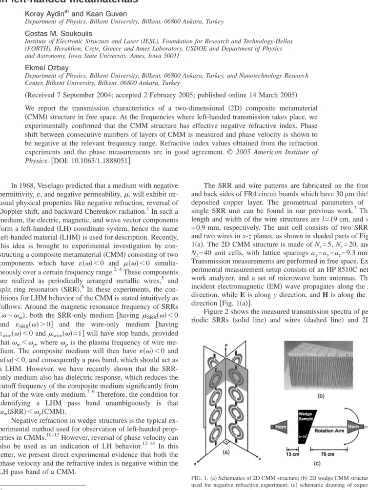
The SRR and wire patterns are fabricated on the front and back sides of FR4 circuit boards which have 30µm thick deposited copper layer. The geometrical parameters of a single SRR unit can be found in our previous work.7 The length and width of the wire structures are l = 19 cm, and w = 0.9 mm, respectively. The unit cell consists of two SRRs and two wires in x-z planes, as shown in shaded parts of Fig. 1共a兲. The 2D CMM structure is made of Nx= 5, Ny= 20, and Nz= 40 unit cells, with lattice spacings ax= ay= az= 9.3 mm. Transmission measurements are performed in free space. Ex-perimental measurement setup consists of an HP 8510C net-work analyzer, and a set of microwave horn antennas. The incident electromagnetic共EM兲 wave propagates along the x direction, while E is along y direction, and H is along the z direction关Fig. 1共a兲兴.
Figure 2 shows the measured transmission spectra of pe-riodic SRRs 共solid line兲 and wires 共dashed line兲 and 2D
a兲
Electronic mail: [email protected]
FIG. 1.共a兲 Schematics of 2D CMM structure; 共b兲 2D wedge CMM structure used for negative refraction experiment;共c兲 schematic drawing of experi-mental setup used for refraction experiment.
APPLIED PHYSICS LETTERS 86, 124102共2005兲
CMM between 3 and 7 GHz. The band gap of SRR between 3.55 and 4.05 GHz is due to magnetic resonance of periodic SRR medium, hence共兲⬍0 for this frequency range.7The 2D CMM structure allows propagation of EM waves be-tween 3.7 and 4.1 GHz, where both and are negative. The CMM pass band coincides with the stop band of SRR. The transmission peak at 3.92 GHz is ⫺10.2 dB, which is significantly higher than the previously reported 2D CMM structures.3,11We also reported high transmission共⫺1.2 dB兲 for 1D CMM structures with the same parameters7 so it is not surprising to obtain high transmission for the 2D case. The high transmission can be explained by better impedance matching between air and CMM for this particular CMM design. The transmission band starting from 5.3 GHz is due to downward plasma frequency shift, since the⬎0 regime of the combined electric response of SRRs and wires starts at 5.3 GHz.7
For negative refraction experiments, a prism shaped 2D CMM structure is constructed关Fig. 1共b兲兴. The minimum and maximum number of unit cells at the propagation direction is 3 and 19, which results in a wedge angle of= 26°. Figure 1共c兲 depicts the schematic of the experimental setup. The source is 13 cm共⬃2兲 away from the first interface of the wedge. Full width half maximum of the beam共9.5 cm兲 at the first interface is smaller than the size of the incident surface 共34 cm兲. Receiver antenna is mounted on a rotating arm to obtain the angular distribution of the transmitted signal. Re-ceiver antenna is located at a distance of 70 cm共⬃10兲 away from the second interface of the wedge.
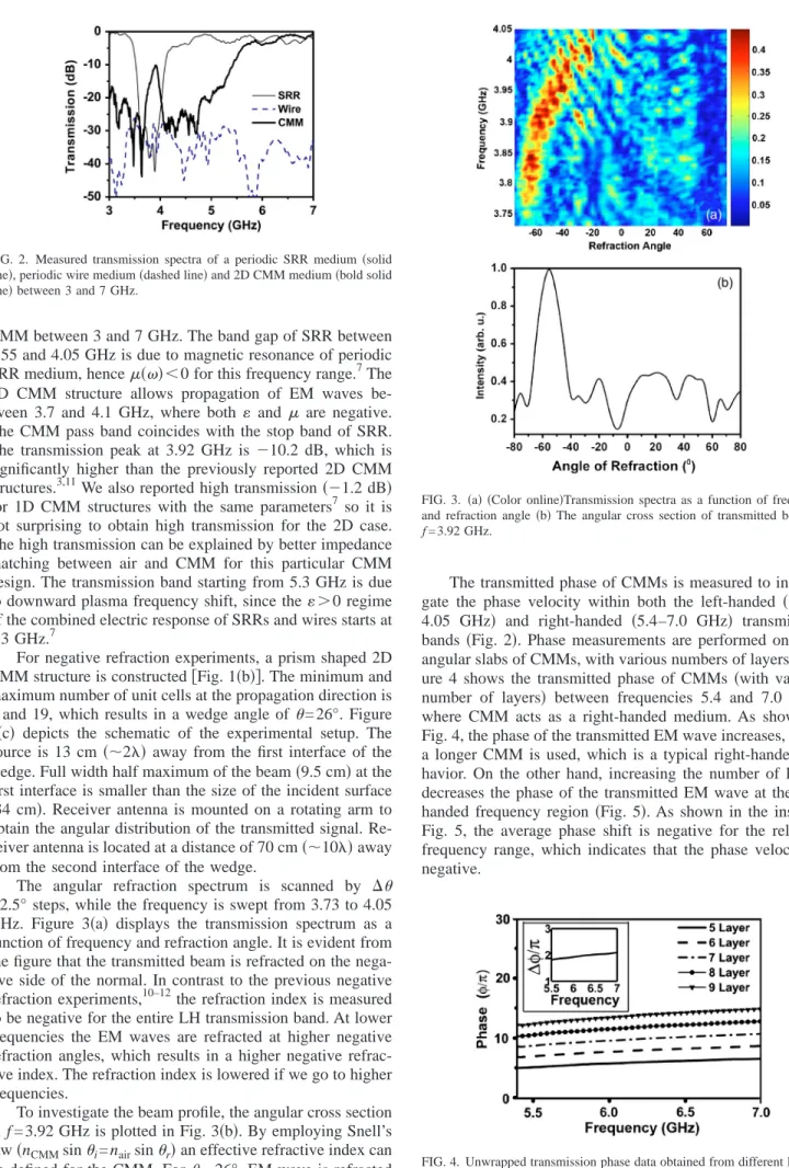
The angular refraction spectrum is scanned by ⌬ = 2.5° steps, while the frequency is swept from 3.73 to 4.05 GHz. Figure 3共a兲 displays the transmission spectrum as a function of frequency and refraction angle. It is evident from the figure that the transmitted beam is refracted on the nega-tive side of the normal. In contrast to the previous neganega-tive refraction experiments,10–12the refraction index is measured to be negative for the entire LH transmission band. At lower frequencies the EM waves are refracted at higher negative refraction angles, which results in a higher negative refrac-tive index. The refraction index is lowered if we go to higher frequencies.
To investigate the beam profile, the angular cross section at f = 3.92 GHz is plotted in Fig. 3共b兲. By employing Snell’s law共nCMMsini= nairsinr兲 an effective refractive index can be defined for the CMM. Fori= 26°, EM wave is refracted at an angle ofr= 55°, then from Snell’s law we obtain neff
= −1.87± 0.05 at 3.92 GHz.
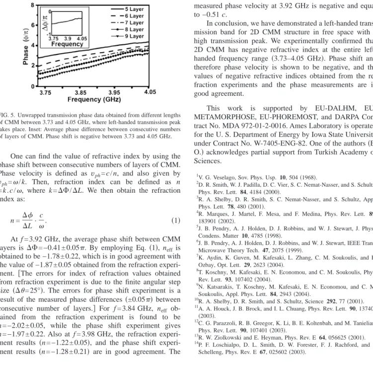
The transmitted phase of CMMs is measured to investi-gate the phase velocity within both the left-handed 共3.73– 4.05 GHz兲 and right-handed 共5.4–7.0 GHz兲 transmission bands共Fig. 2兲. Phase measurements are performed on rect-angular slabs of CMMs, with various numbers of layers. Fig-ure 4 shows the transmitted phase of CMMs 共with varying number of layers兲 between frequencies 5.4 and 7.0 GHz, where CMM acts as a right-handed medium. As shown in Fig. 4, the phase of the transmitted EM wave increases, when a longer CMM is used, which is a typical right-handed be-havior. On the other hand, increasing the number of layers decreases the phase of the transmitted EM wave at the left-handed frequency region共Fig. 5兲. As shown in the inset of Fig. 5, the average phase shift is negative for the relevant frequency range, which indicates that the phase velocity is negative.
FIG. 2. Measured transmission spectra of a periodic SRR medium共solid line兲, periodic wire medium 共dashed line兲 and 2D CMM medium 共bold solid line兲 between 3 and 7 GHz.
FIG. 3. 共a兲 共Color online兲Transmission spectra as a function of frequency and refraction angle共b兲 The angular cross section of transmitted beam at
f = 3.92 GHz.
FIG. 4. Unwrapped transmission phase data obtained from different lengths of CMM between 5.4 and 7.0 GHz, where right-handed transmission peak takes place. Inset: Average phase difference between consecutive numbers of layers of CMM. Phase shift is positive between 5.4 and 7.0 GHz.
One can find the value of refractive index by using the phase shift between consecutive numbers of layers of CMM. Phase velocity is defined as vph= c / n, and also given by vph=/ k. Then, refraction index can be defined as n = k . c /, where k =⌬⌽/⌬L. We then obtain the refraction index as:
n =⌬
⌬L·
c
. 共1兲
At f = 3.92 GHz, the average phase shift between CMM layers is ⌬⌽=−0.41±0.05. By employing Eq. 共1兲, neff is
obtained to be −1.78 ± 0.22, which is in good agreement with the value of −1.87 ± 0.05 obtained from the refraction experi-ment. 关The errors for index of refraction values obtained from refraction experiment is due to the finite angular step size 共⌬= 25°兲. The errors for phase shift experiment is a result of the measured phase differences共±0.05兲 between consecutive number of layers.兴 For f =3.84 GHz, neff
ob-tained from the refraction experiment is found to be n = −2.02 ± 0.05, while the phase shift experiment gives n = −1.97 ± 0.22. Also at f = 3.98 GHz, the refraction experi-ment results 共n=−1.22±0.05兲, and the phase shift experi-ment results 共n=−1.28±0.21兲 are in good agreement. The
measured phase velocity at 3.92 GHz is negative and equal to −0.51 c.
In conclusion, we have demonstrated a left-handed trans-mission band for 2D CMM structure in free space with a high transmission peak. We experimentally confirmed that 2D CMM has negative refractive index at the entire left-handed frequency range 共3.73–4.05 GHz兲. Phase shift and therefore phase velocity is shown to be negative, and the values of negative refractive indices obtained from the re-fraction experiments and the phase measurements are in good agreement.
This work is supported by EU-DALHM, EU-METAMORPHOSE, EU-PHOREMOST, and DARPA Con-tract No. MDA 972-01-2-0016. Ames Laboratory is operated for the U. S. Department of Energy by Iowa State University under Contract No. W-7405-ENG-82. One of the authors共E. O.兲 acknowledges partial support from Turkish Academy of Sciences.
1
V. G. Veselago, Sov. Phys. Usp. 10, 504共1968兲. 2
D. R. Smith, W. J. Padilla, D. C. Vier, S. C. Nemat-Nasser, and S. Schultz, Phys. Rev. Lett. 84, 4184共2000兲.
3
R. A. Shelby, D. R. Smith, S. C. Nemat-Nasser, and S. Schultz, Appl. Phys. Lett. 78, 480共2001兲.
4
R. Marques, J. Martel, F. Mesa, and F. Medina, Phys. Rev. Lett. 89, 183901共2002兲.
5
J. B. Pendry, A. J. Holden, D. J. Robbins, and W. J. Stewart, J. Phys.: Condens. Matter 10, 4785共1998兲.
6
J. B. Pendry, A. J. Holden, D. J. Robbins, and W. J. Stewart, IEEE Trans. Microwave Theory Tech. 47, 2075共1999兲.
7
K. Aydin, K. Guven, M. Kafesaki, L. Zhang, C. M. Soukoulis, and E. Ozbay, Opt. Lett. 29, 2623共2004兲.
8
T. Koschny, M. Kafesaki, E. N. Economou, and C. M. Soukoulis, Phys. Rev. Lett. 93, 107402共2004兲.
9
N. Katsarakis, T. Koschny, M. Kafesaki, E. N. Economou, and C. M. Soukoulis, Appl. Phys. Lett. 84, 2943共2004兲.
10
R. A. Shelby, D. R. Smith, and S. Schultz, Science 292, 77共2001兲. 11
A. A. Houck, J. B. Brock, and I. L. Chuang, Phys. Rev. Lett. 90, 137401 共2003兲.
12
C. G. Parazzoli, R. B. Greegor, K. Li, B. E. Koltenbah, and M. Tanielian, Phys. Rev. Lett. 90, 107401共2003兲.
13
R. W. Ziolkowski and E. Heyman, Phys. Rev. E 64, 056625共2001兲. 14
P. F. Loschialpo, D. L. Smith, D. W. Forester, F. J. Rachford, and J. Schelleng, Phys. Rev. E 67, 025602共2003兲.
FIG. 5. Unwrapped transmission phase data obtained from different lengths of CMM between 3.73 and 4.05 GHz, where left-handed transmission peak takes place. Inset: Average phase difference between consecutive numbers of layers of CMM. Phase shift is negative between 3.73 and 4.05 GHz.