T.C.
ISTANBUL AYDIN UNIVERSITY INSTITUTE OF GRADUATE STUDIES
CONTROL MICROGRID WITH RENEWABLE ENERGY SOURCE AND MULTIPLE CONVERTERS
THESIS
Shahbaz LATIF
Department of Electrical & Electronic Engineering Electrical and Electronics Engineering Program
T.C.
ISTANBUL AYDIN UNIVERSITY INSTITUTE OF GRADUATE STUDIES
CONTROL MICROGRID WITH RENEWABLE ENERGY SOURCE AND MULTIPLE CONVERTERS
THESIS
Shahbaz LATIF (Y1813.300017)
Department of Electrical & Electronic Engineering Electrical and Electronics Engineering Program
DECLARATION
I hereby declare with respect that the study “Control Microgrid With Renewable Energy Source And Multiple Converters”, which I submitted as a Master thesis, is written without any assistance in violation of scientific ethics and traditions in all the processes from the Project phase to the conclusion of the thesis and that the works I have benefited are from those shown in the Bibliography.(.../.../20...)
To God, who continues to guide me and give me strength throughout all challenges.
To my dear parents, who taught me to believe in myself.
FOREWORD
First of all, I would like to express my endless gratitude to ALLAH for being who I am right now and helping me to find patience, strength with in myself to complete this thesis.
I would also like to thank my family not only for encouraging me to go abroad for Master’s degree, but also for teaching me to chase my dream sand never give up. I can not express how grateful I am for having such a loving family that always believes in me. Moreover, my family is my source of inspiration and engine that helps me to improve and move on. I can not mention the patience and support that they showed with in this period of my life. Behind of any my success there is a hard work of my dear parents.
I feel very fortunate to have Assist. Prof. Dr. Murtaza Farsadi as my supervisor and want to express my appreciation for guiding me with in whole research process in a patient and effective manner. Assist. Prof.Dr.Murtaza Farsadi is not only professional in his area, but a person with a grea the art that keep sencouraging the students.
I would like to thank chairman of Electrical & Electronics Engineering Department Prof. Dr Nadim Tutkun for continuous support and understanding during research period. Finally, I would like to acknowledge the important contribution of Istanbul Aydin Universitytomy life not only from academic perspective but helping to meet great people that inspire, challenge, support and motivate me.
June, 2020 Shahbaz LATİF
TABLE OF CONTENT Page FOREWORD ... v TABLE OF CONTENT ... vi ABBREVIATIONS ... viii LIST OF FIGURES ... ix LIST OF TABLES ... x ABSTRACT ... xi ÖZET...xii 1. LITERATURE REVIEW ... 1
1.1 PLUG and PLAY Power... 1
1.2 Trends in micro-grid control ... 2
1.3 Real World micro-grids –An overview ... 2
1.4 Control and power management ... 3
1.5 Multiple input DC-DC converter ... 4
1.6 Power Quality Control inHybrid Micro-Grid system ... 5
1.7 Energy storage control in Renewable energy based Micro-Grid ... 6
2. MICRO-GRID ... 7
2.1 Modes of operation ... 8
2.1.1 Grid-connected Mode ...8
2.2 Islanded mode operation ... 9
2.3 Classification of Micro Grid ... 9
2.3.1 AC coupled Micro-Grids ... 10
2.3.2 DC coupled Micro-Grids ... 10
2.3.3 Micro Grid control system ... 10
3. MICRO GRID PROTECTION SYSTEM ... 13
3.1 Factors considered while designing protection system ...13
3.2 Methods of Protecting a MicroGrid ...14
4. ENERGY STORAGE TECHNOLOGIES IN MICRO-GRIDS... 16
4.1 Types of Storage Batteries ...16
4.1.1 Lead Acid batteries ... 16
4.1.2 Lithium ion batteries ... 16
4.1.3 Sodium Ions battery ... 16
4.1.4 Flywheels ... 17
4.1.5 Super capacitor ... 17
4.2 Sizing of backup storage for Micro-Grids ...18
5. MICRO GRID CONTROL TECHNIQUES ... 20
5.1 PQ control ...20
6.1.1 Batteries as Energy Storage ... 25
6.1.2 Photovoltaic Cells ... 26
6.1.3 Wind Turbine ... 28
6.2 Control Philosophy ...30
6.3 Proportional Integration Control ...31
6.4 Modelling of micro grid using PI Controller ...32
6.5 Simulation Result of PI Controller for Micro grid ...34
6.6 PR Controller ...35
6.7 Experimental modelling for PI and PR controller ...36
6.8 Advantages of PR Controller over PI Controller ...40
7. CONCLUSION ... 42
REFERENCES ... 43
ABBREVIATIONS
CAN : Control Area Netwok CSU : Current Sensing Unit DC : Direct Current
DFT : Discrete Fourier Transform DG : Distributed Generator DSP : Digital Signal Processing ESS : Energy Storage System FCL : Fault Current Limiter
FESU : Flywheel Energy Storage Unit
FHES : Fuel Cell, Hydrogen Tank and Electrolyzer System FPGA :Field Programmable Gate Array
FQB : Frequency Reactive Power Boost IPEM : Integrated Power Electronics Module LC : Local Control
MCC : Micro Grid Control Center MG : Micro Grid
PCC : Point of Common Coupling PoC : Point of Coupling
SKIIP : SEMIKRON intelligent integrated power SOC : State of Charge
SSFCL: Solid State Fault Current Limiter SST : Solid State Transformer
VPD : Voltage Power Droop VSC : Voltage Source Contverters
LIST OF FIGURES
Page
Figure 1.1:Proposed Hardware Interface (Hou et al., 2011) ... 1
Figure 1.2: Micro-Grid technologies(Barnes et al., 2007) ... 3
Figure 1.3:Micro-grid Phase Voltage Transient ... 4
Figure 1.4: Multiple input converter topology ... 5
Figure 1.5: Proposed Micro-Grid network ... 6
Figure 2.1:Micro-Grid concept ... 7
Figure 2.2: Transition between modes of operation ... 9
Figure 2.3:A CB on connection to Grid ... 11
Figure 5.1:PQ Control schematic ... 20
Figure 5.2:V/f control schematic ... 21
Figure 5.3:relationship between active power output and frequency ... 22
Figure 5.4:Relationship between reactive power output and voltage ... 22
Figure 6.1: Micro-Grid ... 24
Figure 6.2: Battery Bank Charging ... 25
Figure 6.3: Battery Bank Discharging ... 26
Figure 6.4: Photovoltaic Cells ... 26
Figure 6.5: Photovoltaic Cell Equivalent Circuit ... 27
Figure 6.6: PV Cells Modelling... 28
Figure 6.7: Wind Turbine ... 29
Figure 6.8:Wind Turbine Modelling ... 29
Figure 6.9: Flow Chart ... 30
Figure 6.10: Simulink model of hybrid micro-grid ... 31
Figure 6.11:.1 at 100 KW: Voltage and Power from Utility to Load ... 37
Figure 6.12:.2 at Load of 100KW: Voltage, Current and Power from Solar grid to Load ... 37
Figure 6.13: .3 at Load of 100KW: Voltage, Current and Real Power at Load ... 38
Figure 6.14: For Load 100 KW and 5 KVAR: Voltage, Current, Real Power and Reactive Power from Utility to Load ... 38
Figure 6.15:For Load = 100 KW and 5 KVAR: Voltage, Current, Real Power and Reactive Power from Solar Grid to Load ... 39
Figure 6.16: Above fig shows voltage,, current, dc-link voltage and rotor speed of wind generator ... 39
Figure 6.17: For Load = 100 KW and 5 KVAR: Voltage, Current, Real Power and Reactive Power at Load ... 40
LIST OF TABLES
Page
Table 4:1: Characterstic Comparision Table ... 17
Table 4:2: Advantages and disadvantages of different storage types ... 18
Table 6.1: Comparison between THD Values ... 36
CONTROL MICROGRID WITH RENEWABLE ENERGY SOURCE AND MULTIPLE CONVERTERS
ABSTRACT
Micro-Grid technology is an emerging field and it is the interest area of researchers working specially on energy sectors. As our country is facing energy crises from many years and it is expected to reach severity level in future as the fuel prices are increasing. The single point of power generation cannot overcome the short fall currently facing the country. The industries for instance sugar and textile generating energy and exporting excessive energy to national grid.
These days, the main focus for power generation is to utilize renewable energy sources. There are solar parks and wind energy farm are being constructed and their numbers are increasing day by day which are no doubt the major sources for reducing energy crises in the country.
In this thesis, study on small scale power generation unit is being considered spread over a city to overcome energy crises. The terminology used for these small scale energy unit is Micro-grid. The problem with these micro-grid is that of synchronisation with the main grid that is when the main grid is off line, these micro-grid should be synchronised in such a way that they can export sufficient energy to the main grid.
This thesis addresses this issue by improving a control scheme for renewable energy resources and multiple convertors for energy storage system.
Keywords: Micro-grid, renewable energy, Droop Control, Model Predictive control, multi agent system, islanded modes, Wind Turbine, Energy storage system, Photovoltaic cells.
YABANCI DİL KAYGISININ ORTAOKUL ÖĞRENCİLERİ ÜZERİNDEKİ ETKİLERİ
ÖZET
Mikro-Şebeke teknolojisi gelişmekte olan bir alandır ve özellikle enerji sektörlerinde çalışan araştırmacıların ilgi alanıdır. Ülkemiz uzun yıllardan beri enerji krizleriyle karşı karşıya olduğu için yakıt fiyatları arttıkça gelecekte şiddet seviyesine ulaşması beklenmektedir. Elektrik üretimindeki tek nokta, şu anda ülkenin karşı karşıya olduğu kısa düşüşün üstesinden gelemez. Örneğin şeker üreten ve enerji üreten ve ulusal şebekeye aşırı enerji ihraç eden tekstil sektörleri.
Bugünlerde elektrik üretiminin ana odağı yenilenebilir enerji kaynaklarından faydalanmaktır. Güneş parkları var ve rüzgar enerjisi çiftliği inşa ediliyor ve sayıları her geçen gün artıyor, bu da ülkedeki enerji krizlerini azaltmak için önemli kaynaklar.
Bu tezde, enerji krizlerinin üstesinden gelmek için küçük ölçekli enerji üretim birimi üzerine yapılan bir çalışma bir şehre yayılmış olarak değerlendirilmektedir. Bu küçük ölçekli enerji birimi için kullanılan terminoloji Mikro şebekedir. Bu mikro şebekedeki sorun, ana şebeke kapalı olduğunda ana şebekeyle senkronizasyondur, bu mikro şebeke ana şebekeye yeterli enerji verebilecek şekilde senkronize edilmelidir. Bu tez, yenilenebilir enerji kaynakları için bir kontrol şemasını ve enerji depolama sistemi için çoklu dönüştürücüler geliştirerek bu sorunu ele almaktadır.
1. LITERATURE REVIEW
1.1 PLUG and PLAY Power
This paper presents a new hierarchical approach for power electronics based interface between distributed energy resources and grid. The author primarily focusses on improvement in voltage stabilization, optimization of power flow and improved in voltage stability. To achieve this author proposes (Hou, Hu, &Hui, 2011)
Paper demonstrates a simulation of a 3-phase grid connected converter for lithium battery energy storage system model, and integrates a SKIIP based on IPEM. The controller for implementation of IPEM is made using DSP and FPGA with different communication interfaces.(Hou et al., 2011)
Heat Sink
V Sensor I Sensor T Sensor Power Stage Circuit Controller Interface
Power Supply Signal Processing Circuit
Go to Driver Protection
Lower Hardware Control Module
Figure1.1: Proposed Hardware Interface (Hou et al., 2011)
Experimental results shown in this paper show improved flexibility and processing rate because of FPGA and DSP's plus envisions a plug and play power electronic interface for micro-grid control.
1.2 Trends in micro-grid control
This paper thoroughly reviews different trends of micro -grid control and major challenges in it. After peer review authors compare and place different control techniques under different levels, namely -primary, secondary & tertiary where former two levels deals with operation of micro-grid while tertiary level is associated with coordinated operation of micro-grid and host-grid. The paper focusses on mostly control techniques of primary and secondary levels e.g Droop Control, Model Predictive control and Multi-agent systems etc.(Olivares et al., 2014)
Paper weighs on ESS as key-technology for intermittent renewable source integration but also highlights that resource management challenge with it, other than that issue like low inertia of power-electronic interfaced units, low voltage grid's lower X/R ratio, uncertainty of generation output etc. With some issues addressed while other proposed techniques are yet to be tested (Olivares et al., 2014)
1.3 Real World micro-grids –An overview
This paper again is review paper that not only compares various micro -grid structures and highlights the operation control techniques used or proposed for micro-grid structures that are already operational or to be soon operationalized, around the globe.(Barnes et al., 2007)
The paper sheds light on various micro-grid projects and tries to establish the fact that how this has become a 'buzz-word' for various enhanced micro-generation system's types. The author sheds light on how all of these systems somehow have a virtual or physical prime-mover arrangement and its effectiveness with reference to its location near point -of-coupling. Behavior of PoC and how modern day micro-grids are less reliant on it. Authors try to present the real world projects as hard demonstrators of their findings which makes paper quite effective (Barnes et al., 2007)
Central Control CI PE PE PE PE PE G M Point of Coupling POC Utility Network 1 2 3 4 5 6 7 PE Possible Power Electronic Interface
CI Connection Interface
Communication Line VI Sensor
G Generator
M Motor
Figure1.2: Micro-Grid technologies(Barnes et al., 2007) 1.4 Control and power management
This papers suggests a controlling scheme for parallel operation of voltage source converters fed micro-grid in parallel usingvoltage and frequency boost techniquesVPD/FQB.(Sao & Lehn, 2008)
The paper presents a way of controlling options in both grid controlled and islanded modes using multiple voltage source converters with dq-frame current controls and standard inductor interfaces to operate in parallel. The technique also enables frequency and voltage regulation, inherent over current protection of VSC in islanded mode. Joint voltage regulation and frequency regulation is achieved by drooping voltage and frequency references YPD/FQB controller against d-axis and q-axis of corresponding VSC.
The test result show following voltage and frequency transients and imply that VPD/FQB control schemes are robust islanding transients.(Sao & Lehn, 2008)
Figure1.3:Micro-grid Phase Voltage Transient 1.5 Multiple input DC-DC converter
This paper comprehensively suggests an application oriented micro-grid i.e. a telecom power plant based upon modular architecture. Paper explains why such system would be cost effective and also conceptualizes the required architecture and not just that but also sheds light on other similar researches carried out.(Kwasinski&Krein, 2005)
The paper suggests that a micro-grid architecture fed through multiple input dc-dc converters is scalable and cost effective.
The suggested topology of converters and rectifiers as shown below can help create highly flexible plant that can be configured based on power budget.(Kwasinski&Krein, 2005)
VB1 LB1 QB1 C R + V -IO LB1 IB1 IB2 VB2 QB2 VBB2 IBB2 VBB1 QBB1 LBB IOBB QBB2 IBB1
Figure1.4:Multiple input converter topology
Starting cost saving is achieved by reduced energy storage capacity and support facilities which is further complemented by 150V dc as primary distribution voltage. With the help of bi-directional converters, the energy storage devices are connected to 150v dc bus.
1.6 Power Quality Control inHybrid Micro-Grid system
Stability and power quality of micro-grid can be affected with different kinds of power sources. This paper focusses on a technique where combining micro -turbine and fuel cell, Hydrogen tank and Electrolyzer system Hybrid System (FHES) to enhance micro-grid system's ability to address power quality issue of frequency fluctuation. (Li, Song, & Han, 2007) Effective utilization of load controllable electrolysers system can significantly improve power quality for frequency. The paper also discusses that PI compensator can be used to compensate power changes at Micro-grid system and tie line. With experimental results paper also deduces that by applying smaller Tes (Time constant for ES) to control ES load rapidly can be effective in upgrading operation capability of handling frequency fluctuation. (Li et al., 2007)The micro-grid system based on pc control and monitoring, through CAN communication system, comprising of a micro turbine to supply base load, an electrolyzer to create Hydrogen,
hydrogen storage tank ,renewable energy based generators and proton exchange membrane fuel cell is envisioned. (Li et al., 2007)
WP PV MT House VCB TR House House House PCMS
Figure1.5:Proposed Micro-Grid network
1.7 Energy storage control in Renewable energy based Micro-Grid
This paper deals with the role of Energy storage in Renewable sources based micro-grid and also identifies the works that has been done in this regard. The paper gives reference to a micro grid project funded to test the control techniques and energy storage in renewable micro-grids.(Tang & Qi, 2012) The paper highlights how Distributed Energy Resources have become so important and an enhanced micro-grid, the only viable solution that can work in islanded, grid-tied modes & also smoothly transits between two modes. The paper focusses on how renewable energy based micro-grids can have black start support, stable control support and improved power quality (such as DC voltage offset, frequency distortion and harmonics etc.)(Tang & Qi, 2012)
2. MICRO-GRID
Traditional definition of micro-grid may vary but with introduction of new trends in energy storage and control techniques the micro-grid can be defined as combination of Distributed Generation systems, a group of loads and Energy storage systems(ESSs) using various control techniques to supply uninterrupted electricity with respect to a Common Coupling Point connection with host Grid at distribution level
(Kalpesh C. Soni&Belim, 2015) Such isolated micro-grids have also been existed in past in remote areas where host power system distribution could 'not reach, fulfilling needs of a local community. With integration of renewable energy sources, the roads to heavy investment in micro -grids have been opened specially after introduction of smart grids. But in order to successfully integrate renewable energy sources with micro-grid, researchers have to overcome a lot of challenges.(Olivares et al., 2014) DG DG DG DG A B C 16 22 8 C 11 Static Switch PCC Grid
Non Sensitive Load Sensitive Load
The distributed Generation (DG) close to the load reduces dependency upon Centralized Power System from the view-point that new technology reduces line losses, infrastructure costs, load shedding , congestion of network and also allows one to be consumer and producer at the same time , saving many from heavy bills of utility companies, thanks to renewable resources like Wind and Solar.(Yeshalem& Khan, 2018)
2.1 Modes of operation
Micro-grid works in two modes of operation
Grid connected mode
Islanded mode
2.1.1 Grid-connected Mode
This mode of operation may be defined as micro-grid connected to host power network at point of common coupling and exchanges power with it. When load is more than distributed generation, micro-grid inhales power from main distribution network and in other case injects excess power to main grid. The distribution network dispatch layer connects with centralized control layer of micro-grid at and share amount of power exchange at PCC to dispatch centre in order to regulate distributed generation output, energy storage and load in order to balance active & reactive power, and micro-grid status (connected/disconnected) (Ahmed, Amin, Aftab, & Ahmed, 2015; Yeshalem& Khan, 2018)
This type of arrangement is aimed at increasing energy efficiency and load shifting with the help of energy storage's charge & discharge and by time-of-use tariff. (Ahmed et al., 2015; Augustine, Suresh, Moghe, & Sheikh, 2012).
Under this arrangement, micro-grid can be considered as controllable load w.r.t main grid where it manages power factor under uniform power factor and is not allowed to manage grid voltage. With the help of reactive output of Distributed
2.2 Islanded mode operation
As micro-grid separates from main grid its transits into islanded mode in order to supply uninterrupted power to various loads. This means that DGs, ESs and loads of micro-grid will operate independently. If changes in DG system's output or fluctuation of load occurs and is beyond the capacity of ES to compensate then voltages and system frequency may drop which results in load shedding.it is also possible that in above given circumstances that system voltage and frequency may rise instead of dropping, if such case occurs output of some DG's will be limited until things return to normalcy.Incase if dispatch able DG's produced output is maximum, and the SOC of ES is below lower limit, load shedding of unimportant loads can occur. Various control techniques are employed to control frequency deviation and inertia of system like droop-control method.
(Ahmed et al., 2015; Tang & Qi, 2012; Yeshalem& Khan, 2018).
Transition between modes of operation is itself a very deep topic and is beyond the scope of this thesis but a few control techniques will be discussed later.
Figure2.2:Transition between modes of operation
2.3 Classification of Micro Grid
AC Coupled Micro-Grid
DC Coupled Micro-Grid
2.3.1 AC coupled Micro-Grids
In a centralized ac coupled micro-grid all power producing elements are linked to AC bus either directly or with the help of AC-AC converters, in order to get a certain coupling technology.to control the flow of energy master inverters are employed.
In ac coupled de-centralized micro-grid , technology is not linked with a bus bit rather directly with the load energy resources may not be available at same location thus power generating components can be installed an ywhere resources are available. But its control system is very complex as compared to centralized grid(Yeshalem& Khan, 2018)
2.3.2 DC coupled Micro-Grids
In such type of configuration all energy sources are linked to DC bus before being linked with AC bus with the help of converter, if required AC load is provided using inverter. A charge controller is used to avoid de ep discharge and over-charge .Disadvantage of such configuration is low conversion efficiency.(Yeshalem& Khan, 2018)
2.3.3 Micro Grid control system
Micro Grid control system must be paced at different multiple levels of the system and must enable persistent communication between different control units in order to cope up with continuously variable output of distribut ed generators and load demand changes with time. Head of this hierarchical control system is a dedicated micro grid central controller installed at medium/low voltage substation, manages micro grid and supervisory control, integrated it with main gird and also communicated between network operators. (Yeshalem& Khan, 2018)Transition between gird connected and islanding mode is done via a central switch which also enables synchronization between both
Switch interconnection technology in a micro grid uses Digital signal processor technology and is provided with relevant communication devices, coherent with IEEE 1574 Standard Network Interconnection. Below given figure is a schematic of circuit breakers on connection to grid.(Hartono &Setiabudy, 2013; Yeshalem& Khan, 2018)
DSP: Relay + Comm + Monitoring/ Diagnostic
Measurement Communication PT PT 3 CT CT DG Load Utility Grid
Figure2.3: A CB on connection to Grid
Control system of a micro-grid is designed in such a way so as to cater its steady state and dynamic characteristics. Micro Grid has inbuilt unbalanced load due to one phase loads, and the supply of power comes from uncontrolled sources such as Solar. Large role of energy storage systems and accommodation of connection and disconnection mechanism to manage operational expenses.For certain types of loads, MGs require service preference and power quality initially. To address these type of issues micro grid control system has to be different from that of a conventional power system.(Hartono &Setiabudy, 2013).
Micro grid Control Centre (MCC) determines power output from each Local Control, on the basis of input production capacity owned by each Local Control (LC).MCC predicts, upon these inputs and operating policy, needs and production plus also infrastructure condition consideration of other microgird.It also determines LC operations which includes setting LC production capacity,
amount of loads to be served and market price for energy optimization of LC.(Hartono &Setiabudy, 2013)
3. MICRO GRID PROTECTION SYSTEM
Although renewable micro-grids are an effective replacement to fossil fuel based production, but there are a lot of challenges while maintaining micro grid protection system because of its dynamic nature and modes of operation (connected or islanded).Various factor are considered while designing a micro gird protection system and various techniques can be employed.
3.1 Factors considered while designing protection system
Below discussed are a few important factors considered while designing a protection system.
Type of Grid is a crucial factor in protection system, whether a grid is AC coupled or DC coupled or mixed coupled. Type of loads, network and converters used as well as different type of distributed generators have different outputs and accordingly loads , therefore type of grid plays an important part .As for bus protection differential protection is preferred for both type of grids. Main difficulty is with D.C grids because of lacks of experience, therefore one has to pin on AC options available that can be implied to DC grids also keeping in mind the rating differences for both type of operations. Different type of fuses , switches and circuit breakers are used for protection but the problem arises in case of DC where time constant is great and circuit breakers operate with delay so dedicated electronic switch based circuit breakers are used for DC Micro Grids.(Ahmed et al., 2015; Hosseini, Abyaneh, Sadeghi, Razavi, &Nasiri, 2016; Meng et al., 2017).
Topology of MG also comes into play, whether it's looped or meshed topology, because this affects direction and magnitude of fault currents and hence protection plan for upstream and downstream branches is changed accordingly. Types of Distributed Generation units also are important in this situation. DG units can be categorized as synchronous, asynchronous and Inverter -Interfaced
DG and in order to observe response each must be modelled, and each modelling of each DG unit is done using different parameters by researchers. These models help us in calculating amount of fault current produced by each of these DG units, their sources impact on operation time of protective devices (over current relays) etc. Electromagnetic characteristics of IIDGs is dependent on topology and controller for converters.(Hosseini et al., 2016; Xiao, Wang, Setyawan, &Xu, 2015).
Communication infrastructures, methods of data acquisition and time delays also play an integral part in MGs. Standard protocols for substation automation are used like IEC 61850. Communication infrastructure may be classified into three categories like local area based, wide area measurement and hybrid scheme. Communication links can be wired or wireless or both. Supervisory remote control unit, Phasor measurement units and protective devices, which are usually set adjacent to fault locations, are informed and various fault identification techniques are used. Time delay affects the speed of communication which in turn affects protection system. Delays are usually related to delay of current and voltage transducers, data processing time , DFT window size , data size of PMUs output , data concentrators and transitions data. Keeping all delays in mind suitable communication guide and mode is chosen.(Hosseini et al., 2016)
3.2 Methods of Protecting a MicroGrid
Changing of protective devices and adjustment of settings is also widely proposed means of protection. Like replacement of non-directional relay with directional one, which suit bi-directional flow of power, changing of settings of protective devices (re-configuration of constraint causing relays) each time a new DG unit is added or topology of network is modified. Relay's overcurrent curves can be changed in order to avoid synchronization problem plus use of microprocessor based re-closers is envisioned to have more options as per the status of DG (connected or disconnected).Researchers also have proposed
1. Other researches carve out idea of disconnecting DG unit from network quickly with help of switches (like GTO's), until network returns to it prior state. This pre-emptive measure is taken by Current Sensing Unit (CSU) which calculates network currents in order to detect any potential fault, usually taking more than seven cycles in order to avoid any fault identification mistake. This method avoids change of protection devices or their settings and is also a low cost solution. Once the fault is removed the DG can be reconnected to the network.
2. Another proposed and efficient ways of protections is using fault current limiter to limit short circuit current. Best located in the branch where DG is installed in series with it, FCL is impedance that is zero under normal condition and increases proportionally thus limiting theshortcircuitcurrent also significantly reducing operation time of over current relay. Solid state fault current limiter SSFCL's and also hybrid FCL are proposed which have multiple paths and are composed of power semiconductor elements, current limiting impedance and mechanical switches and breakers .RL feed-forward and flux charge model feedback algorithms are also suggested for protection.
3. Another suggested method is use of smart solid state transformer to protect micro grid. Method pins on primary voltage of bus which is connected to SST, remains constant even until power rating of SST is greater than its maximum power. Under normal circumstances primary voltage of SST must never be less than 0.9pu.If it falls under 0.8pu it can be predicted that a fault has occurred and this would result in separation of SST from the network and supply of power from DGs and energy storages in secondary of SST.(Hosseini et al., 2016)
4. ENERGY STORAGE TECHNOLOGIES IN MICRO-GRIDS.
With increase in demand of micro grids, there has been a sharp rise in the demand for efficient energy storage systems, esp. Distributed energy storage systems recently. Various researches are under study, as scope of my thesis I will shed light on most used storage technologies that can be classified as electro-chemical, chemical, mechanical, thermal and electrical systems.(Augustine et al., 2012; Gao, 2015; Kamel, Donahue, &Dankworth, 2014; Tang & Qi, 2012)
4.1 Types of Storage Batteries
There are following types of Batteries used in the micro -grid system 4.1.1 Lead Acid batteries
Based upon electro-chemical reaction between anode and cathode, and made of spongy lead cathode, lead dioxide anode and Sulphuric acid as electrolyte, rechargeable lead acid batteries are widely used as energy storage means because of their high efficiency, low cost, and good surge capability with ability tolerate deep discharge cycles varying for different types. However its energy to volume ratio is debatable.(Gao, 2015)
4.1.2 Lithium ion batteries
Three layered lithium ion batteries also make a good share in batteries market. Due to its light weight, good power density and quick response behaviour, and low self-discharge rate they are highly preferred for small electronic devices. It operates in way that resembles a capacitor and are quite expensive ( Gao, 2015; Tang & Qi, 2012)
power density and large battery lifetime (around 10 years).however operational cost is main constraint.(Gao, 2015; Tang & Qi, 2012)
4.1.4 Flywheels
Flywheel energy storages unit (FESU) is a moveable weighted disk that can store kinetic energy. In order to counter gravity the disk is made in such a way that it is perpendicular to the rotor. They act as generators and can be char ged with help of motors when required. It has high power density, long life span and high conversion efficiency. Modern day flywheels can reach up to 16,000 rpm amounting capacity to 25kWH.They have low maintenance cost supported by short response time. (Gao, 2015; Tang & Qi, 2012)
4.1.5 Super capacitor
Made up of stack of single cells , connected in series, packed and immersed into electrolytic solution forming a double-layered charge distribution and an insulator as separator , super-capacitor has a storage capacity of 20-1000 times that of normal capacitor , and a high power density and conversion rate .A super-capacitor is made up of numerous capacitors arranged in series or parallel.(Gao, 2015; Tang & Qi, 2012)
Table4:1: CharactersticComparision Table
Type Energy Density Power Density Response Time Continuous Discharge Time Cycling Time
Flywheel 5–30 400–1500 < 1s 1s–15min Above 20,000
times
Compressed Air 30–60 – 1–10mins Above 1-24Hr Above
100,000 times
Lead Acid 30–50 75–300 <10s 1s-10 hr 2000 times
Lithium-Ion 75–200 150–300 <10s 1s-10 hr <10,000 times
Sodium Suffer 100–250 100–250 <10s 1s-10 hr 2500-6000
times
Super Capacitor 5–10 5–10 <1s 1ms-1 hr 100,000 times
Superconducting Magnet
Table4:2: Advantages and disadvantages of different storage types
Type Advantage Disadvantage
Flywheel High Power Density and quick response time
Low Energy Density Compressed Air Large Capacity, Long
Continuous Discharge Time
Limited Location, Slow response
Lead Acid High Capacity so High Energy Density
Low power Density, low cycling times
Lithium-Ion High Energy Density Small capacity hard for lager application
Sodium Suffer High Energy Density Need high temperature in working process
Super Capacitor High Power Density and quick response time
Low energy density, expensive
Superconducting Magnet
High Power Density and quick response time, High Cycling Time
Low energy density, expensive, magnetic pollution to the environment
4.2 Sizing of backup storage for Micro-Grids
Reliable and effective backup storage for critical loads is very important element in micro grids. Therefore Sizing of backup storage is needs to be carefully chalked out. The backup can be in form of fuel cell or electrical energy storage, when deciding size of storage power rating on basis of load and energy rating on basis of time period is considered.in developing a way to size backup storage consider below given parameters(Mitra, 2010)
SF = primary supply failure event
L= critical loads power failure experience event
R= random variable representing downtime of primary supply
tA = for how long can storage unit support critical load in case of failure
fR (r) = probability density function of R
(4.1)
Now α = 1-A1/ 1-A0, where α is unavailability ratio From above both equations it can be derived that
(4.2)
Which implies to the relation from which required energy storage can be calculated.(Mitra, 2010; Tang & Qi, 2012)
5. MICRO GRID CONTROL TECHNIQUES
For reliable grid operation and smooth function various control techniques are used but 3 main techniques are PQ control V/f control and droop control.
5.1 PQ control
The main objective of this type of control method is that when frequency and voltage deviation occur within a certain limit, the micro source's active and reactive power should remain constant, and in order to achieve that both must be firstly de-coupled. Since this method cannot control voltage and frequency therefore an extra distributed generator is required to regulate both. In grid –tied mode, main power grid is responsible for regulation of voltage and frequency of micro- grid. (Gao, 2015; Olivares et al., 2014)
Figure5.1:PQ Control schematic
To grid
SPWM
dq0 abc
Current
Control P & Q Control
dq0 abc Vdc Va Vb Vc Lf IL Rf Cf Load PLL Uref Udref Uqref ILd ILq ILqref ILdref Urd Urq W Pref Qref Un
5.2 V/f Control
Purpose of this type of control technique is to regulate frequency and voltage magnitudes irrespective of actual active and reactive power outputs of micro-sources. Frequency and voltage controllers regulate active and reactive power respectively in order to achieve given reference values of voltage and frequencies. It's quite common technique in islanded mode.(Gao, 2015)
To grid SPWM V and I Control Voltage Synthesis Droop Control Vdc Va Vb Vc Lf IL Rf Cf Load Uqref Udref Urd Urq Un abc dq0 P&Q Calculation Power Control P Q Pn fn Vn Icn Un IL
Figure5.2: V/f control schematic 5.3 Droop control
With changing load all the time, in a micro-grid, the generators also keep on changing power output depending upon frequency deviations. This relationship can be mathematically described by the given below equation:
(5.1)
where is power change in output.
While system voltage control can be carried out by adjusting reactive power output of micro sources.(Olivares et al., 2014)
Figure5.3: relationship between active power output and frequency
Figure5.4: Relationship between reactive power output and voltage
5.4 Economic dispatch for a micro- grid using renewable sources
Energy Economics is also a term kept in mind whenever a generation plant is setup. Same applies for micro-grid as it is used by a number of customers to meet their energy supply demand, and that depends upon cost/kwH of electricity supplied. For analysing dispatch rate an isolated grid with solar and wind can be considered. Resources maintenance cost, investment cost and generation cost
dispatch able. In formulation of Economic Dispatch these sources are considered as negative loads with a limited prediction accuracy. A micro -grid can be considered with combined heat and power, two conventional generators, wind and solar generations. Different combination of simulation with certain fixed parameters can be simulated in Matlab to obtain different results.
With inclusion of all five generators and no renewable energy credits, the total generation cost is higher since the investment cost for solar is higher.{Yeshalem, 2018 #60}(Ahmed et al., 2015; Augustine et al., 2012)
With no intermittent source included (solar or wind), but only CHP and conventional generators included does not give any profit or loss for micro-grid but makes system highly reliable because of absence of any intermittent resource.
With only wind included, but not solar, along with other generation means the overall system cost reduces since wind has moderate investment cost. Now again consider case with all sources included but along with credits for solar which include federal tax subsidy and tax rebated we can make solar profitable reducing overall generation cost.(Augustine et al., 2012)
6. METHODOLOGY
In this chapter, analyses of micro-grid components will be discussed. Matlab/Simulink has been used for analysis of this study to support proposed hardware
6.1 Tools and Techniques
A micro-grid consists of different energy sources. These sources of energy are integrated to a common DC Bus bar. Power electronic circuits are being used as interfaces between sources and Main grid, Load and energy storage unit as mentioned in the figure 5. The main objective of micro -grid is that during short fall, it meet the demand of the load.The analysis require different sources of energy and for the analysis point of view, three sources of energy are used as show as under:
Energy Storage
Photovoltaic Cells
Wind Turbines
These sources are connected through a common bus bar through which Main grid, Load and Energy storage system are connected.{Alzahrani, 2017}This is depicted in the figure 6.1
Photovoltaic Cell DC/DC Interface Battery DC/DC Interface
Energy Storage System Subsystem
6.1.1 Batteries as Energy Storage
In micro-grid, very important factor comes when there is a short fall and that why energy storage plays a significant role. Itsoptimum stability and synchronise operation with other sources of energy is achieved by positioning of energy storage system between load and renewable sources.{Alzahrani, 2017}The capacity of energy storage is calculated by considering the short fall from main grid. The formula for capacity of energy storage is as under:
(6.1)
Where
isload in Ampere/ Hour during short fall, isnumber of days of short fall, ismaximum depth of discharge of the battery
istemperature correction factor.{Alzahrani, 2017}
The implementation of battery bank charging and discharging as energy storage in Matlab/Simulink has been carried out which is depicted in following figure 6.2 and figure 6.3
Figure6.3: Battery Bank Discharging 6.1.2 Photovoltaic Cells
It is used to covert the sunlight into electricity directly and that is why it is used very frequently in micro-grid. The DC voltage as an output is fed to the inverter and AC power supply is given to the load through inverter. It is the most prevalent and inexpensive energy source in the world. {Alzahrani, 2017}
Figure6.4: Photovoltaic Cells
Where and are normal and diffused solar irradiance respectively while And are tilt factor of difused and reflected part of solar irradiance. The hourly generation of Photovoltaic cells can be calculated by using the following formula:
(6.3)
Where and are reference and smoothing power efficiency of module respectively, is the factor of density of a cell in module, is the temperature coefficient of array is area of photovoltaic cell, is the instantaneous ambient temperature, Normal operating temperature of cell.{Alzahrani, 2017}The equivalent circuit of PV cell is depicted in the figure 6.5
Rsh
Rs
Vd
Id
Io
There is photocurrent source. A diode is connected in parallel with photocurrent source and there is shunt resistor with series resister. This circuit is built into Matlabs/Simulink to verify its nonlinear behaviour of I-V and P-V output characteristics of PV module. It is shown in figure 6.6
Figure6.6: PV Cells Modelling 6.1.3 Wind Turbine
Energy extraction from wind is done with the help of blades in wind turbine, though the action of aerodynamic forces acting upon them. Rotation of drive shaft, connected with the blades, produces variable AC. This variable AC is converted into DC and then back into AC at a specific frequency.Irregular earth's surface and unequal heating up of earth's atmosphere by sun, causes changing pressure in different zones of earth which in turn leads to flow of air from high pressure zones to low pressure ones. The power generated by a wind turbine is shown in Equation (vii). {Grant, 2018}
Since power generated is proportional to the cube of wind speed therefore wind turbines are preferred to be kept in region where average annual wind speeds are high. If wind speeds are too highpitch control can be applied where the angle of the blades are adjusted to reduce the speedof the blades.{Grant, 2018}
(6.4)
The Betz limits states that the power factor coefficient has a limit of 59.7%. The tip speedratio is the relative speed of the rotor and the wind speed. The pitch angle is the relativeangle between the rotor and its axis.{Grant, 2018}
Figure6.7: Wind Turbine
The Simulink model of a wind turbine equation is shown in figure 6.8
6.2 Control Philosophy
There are various method of controlling micro-gird but in this thesis the control strategy for operation of micro-grid is built by considering two modes of operation which are as under:
On Grid System
Off Grid System
Start > Load Power Power Generated from Renewable Sources Off Grid
Energy Storage System On Grid
Sell or Export to Grid
Purchase
Figure6.10: Simulink model of hybrid micro-grid
In this paper a comparison of different controller techniques used in the micro -grid is discussed to control the off/on -grid. Proportional Integration that is PI controller is discussed first and Proportional control used in micro grid is discussed latter and finally comparison of these techniques will be discussed.
6.3 Proportional Integration Control
As in electrical power generation, there are different type of energy sources that is why this system becomes complicated. The Microgrid is in trend is increasing due to installation of small power plant of solar, wind, hydro etc. The fluctuation in output power is a major issue of renewable energy plant and introduce many technical issues likes’ frequency divergence, voltage instability, harmonic etc. on grid side. It is the requirement to maintain the output synchronised with main grid and reduces fluctuation from the output.
The optimum performance of micro grid is achieved by three control frame work which are central, single and decentralized control. In central frame work, all data type of load and generating sources in the micro grid are collected. The control is on the generating units in single control while in decentralised control local controller is used for each distributed generating units local control signal are used in this method.
The complicated micro grid system is controlled by a controller which handle multiple complicated problems. It is the requirement of the controller that it must be intelligent, easily optimise the problem and give a produces a high accurate response in small period of time. In past, a compensation methods, and droop control methods were used but it was not as accurate as PI controller so it is not used.
6.4 Modelling of micro grid using PI Controller
There are two ways of modelling of micro grid control technique. It can be achieved in connected and disconnected mode. Some studies shows that micro grid in disconnected mode is preferred as compare to the connected mode. Number of parameter are required to model the micro grid control. Parameters of different micro sources for instance wind generator, storage system, PV sources are studied before modelling of isolated micro grid. Circuit breakers are used shown in figure, to protect the system from disturbance.
Photovoltaic Source Wind Turbine Generator Battery Storage System DC/AC Ka DC/AC Convertor Convertor Gain
P
wTGP
PVP
BSS Load DC/AC PI Controller DGP
DG LoadP
L1P
L2 fGenerating Units Rated Power (kW)
Solar Panel 30
The table shows the rated power of different generating units and storage
system.
The table shows the applied load and their power consumption. The modelling of micro grid in carried out in mat lab so parameters values are necessary for the frequency response model of the micro grid these values are given in the table.
Parameter Value (pu)
0.42 0.081 0.004 0.1 0.12 0.04 0.166 3 0.0156
The tuning of PI controller is very critical and important and in the industrial system online tuning system is required to tune the parameters of PI controller. But in this paper, Ziegler Nichols method is used for tuning PI controller. The vales of Kp and Ki are 4.0956 and 21.85 respectively. A model of micro grid in
Applied Load Power (kW)
Primary Load 180
isolated condition is very useful for study/ analysis of frequency response model of the system. 1/(1 + Tt/c .S) Interconnected Device 1/(1 + Tinv .S) Inverter PV Model Solar Model WTG Model Wind Generator Model
1/(1 + Tt .S) Generator 1/(1 + Tg .S) P I C o n tr o ll e r 1/R
Micro grid system 1/(D + 2H .S)
1/(1 + TBE .S) Battery Storage System Change of Load
6.5 Simulation Result of PI Controller for Micro grid
There is one of the method used to control the frequency which is droop control method and area control. The PI controller is also used which is regulated and tuned based on certain points called pre-specified operating points. The optimal solution can be achieved by using PI controller. A good controller is controls the sudden changes in the feedback and controls the spikes or variation in the system. A micro grid system is tuned to get the values of Kp the is proportional gain and Ki integral action which are required such that frequency can be restored and for the easily elimination of frequency variations. A suitable amount of fluctuation in the load and variation in the power generation is used to provide a condition for analysis. A secondary controller is used to complete the control action or frequency control of the Microgrid. The figure shows the normal operating condition and at the starting point. Its need to tune by using Ziegler Nichols method.
The simulation of the micro grid model, the gain of PI controller is adjusted . The simulation results optimization capability of the controller. First, it is assumed that in the Micro grid model, the load disturbance is around 220 pu. And it gets statble at 200 pu.
6.6 PR Controller
The Proportional Resonant controller design in discrete domain for regulating active and reactive power output for three phase AC micro grid system. It is not only reducing the steady state error but also synchronised d-q transformation in three phase system. The Voltage Sourced Converter is required to co nfigure
controlled by inverter indirectly. The analysis of PR controller is carried out in discrete domain forward and backward since in continuous domain its observation cannot be directly applied.
6.7 Experimental modelling for PI and PR controller
The experimental modelling for analysis of PI and PR controller is carried out using MATLAB/Simulink. A micro grid of 100KW consists of PV source connected to the main grid is developed. The compensator for PI and PR controller are implemented for the inverters output current regulation. The simulation required parameters which are as in thetable.
Table6.1: Comparison between THD Values
Parameters PI Controller PR Controller
Current 0.0855 0.0642
Voltage 0.0651 0.0441
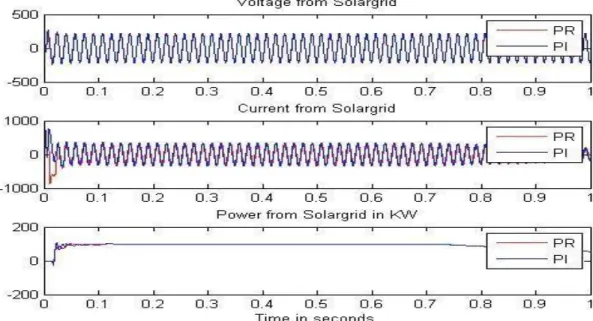
The table shows the THD of current and voltage for PR controller is significantly less than that of PI controller. The simulation has been done for micro-grid at different types of loads for instance, pure resistive load and reactive loads with resistive load. The simulation results are show in figures. The PR controller achieves accurately the required load of 100 KW + 75 KVAR as compare to PI controller which achieves at 90 KW + 71 KVAR which show in the figure.
Figure 6.11:.1 at 100 KW: Voltage and Power from Utility to Load
Figure 6.12:.2 at Load of 100KW: Voltage, Current and Power from Solar grid to Load
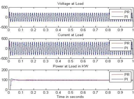
Figure 6.13: .3 at Load of 100KW: Voltage, Current and Real Power at Load
Figure 6.14: For Load 100 KW and 5 KVAR: Voltage, Current, Real Power and Reactive Power from Utility to Load
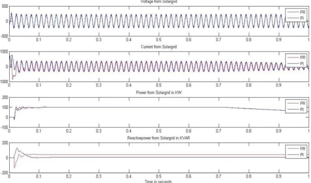
Figure 6.15:For Load = 100 KW and 5 KVAR: Voltage, Current, Real Power and Reactive Power from Solar Grid to Load
Figure 6.16: Above fig shows voltage,, current, dc-link voltage and rotor speed of wind generator
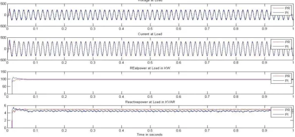
Figure 6.17:For Load = 100 KW and 5 KVAR: Voltage, Current, Real Power and Reactive Power at Load
Table 6.2: Solar and Wind data SOLAR ARRAY + CONVERTER OUTPUT WIND PLANT OUTPUT V 200 V 200 V I 19.4 A 4 A P 3880W 800 W
Input power from sun = 10000 watts BLADE LENGTH 9 m Wind speed 12m/s Overall plant efficiency (3880/10000)
= 38.8%
6.8 Advantages of PR Controller over PI Controller
The grid which are connected to PV Inverter systems are very famous and number of such systems connected to main grid are increasing with the passage of time. The major drawbacks of these systems are due to harmonics generated
controller is not used because it generated error as it go along with reference of sinusoidal wave. Since Integral term is the main cause for producing this steady state error. Hence, there is requirement of the grid voltage as feed forward term which helps the controller to try the steady state at fast rate and obtain a good dynamic response. This is the drawback of PI controller and it leads to development of PR controller. [7]
7. CONCLUSION
Micro-Grid (MG) system that is based on renewable power generation units is presented in this paper. The proposed system has been designed to operate in two operational modes; islanded& grid connected. The system performance is investigated using a simulation based on Matlab/Simulink software package. A control coordinator and monitoring system is also included to monitor micro -grid system state and decide the necessary control action for an operational mode. The system design took into consideration cost reduction through using a single 3-phase inverter instead of three one-phase inverters. Moreover, transformer has been eliminated to supply power to its local loads. It is intended that this work will be the base for the developing more sophisticated Micro -Grid designs.
REFERENCES
[1]Ahmed, M., Amin, U., Aftab, S., & Ahmed, Z. (2015). Integration of Renewable Energy Resources in Microgrid.
[2]Alzahrani, A., Ferdowsi, M., Shamsi, P., &Dagli, C. H. (2017). Modeling and simulation of microgrid.Procedia computer science, 114, 392-400. [3]Augustine, N., Suresh, S., Moghe, P., & Sheikh, K. (2012). Economic
dispatch for a microgrid considering renewable energy cost functions. Paper presented at the 2012 IEEE PES Innovative Smart Grid Technologies (ISGT).
[4]Barnes, M., Kondoh, J., Asano, H., Oyarzabal, J., Ventakaramanan, G., Lasseter, R., . . . Green, T. (2007).Real-world microgrids-an overview. Paper presented at the 2007 IEEE International Conference on System of Systems Engineering.
[5]Gao, D. W. (2015).Energy storage for sustainable Micro-Grid: Academic Press-Elsevier Ltd.
[6]Hartono, B., &Setiabudy, R. (2013).Review of microgrid technology. Paper presented at the 2013 international conference on QiR.
[7]Hosseini, S. A., Abyaneh, H. A., Sadeghi, S. H. H., Razavi, F., &Nasiri, A. (2016). An overview of microgrid protection methods and the factors involved. Renewable and Sustainable Energy Reviews, 64, 174-186. [8]Hou, C., Hu, X., & Hui, D. (2011).Plug and play power electronics
interface applied in microgrid. Paper presented at the 2011 4th International Conference on Electric Utility Deregulation and Restructuring and Power Technologies (DRPT).
[9]Kalpesh C. Soni ,&Belim, F. F. (2015). MicroGrid during Grid-connected mode and Islanded mode - A Review. Paper presented at the National conference on recent research in Engineering and Technology (NCRRET-2015). Review Paper retrieved from
[10]Kamel, M. R., Donahue, P. W., &Dankworth, J. A. (2014). System and methods to wirelessly control distributed renewable energy on the grid or microgrid: Google Patents.
[11]Kwasinski, A., &Krein, P. T. (2005).A microgrid-based telecom power system using modular multiple-input dc-dc converters. Paper presented at the INTELEC 05-Twenty-Seventh International Telecommunications Conference.
[12]Li, X., Song, Y.-J., & Han, S.-B. (2007).Study on power quality control in multiple renewable energy hybrid microgrid system. Paper presented at the 2007 IEEE Lausanne Power Tech.
[13]Meng, L., Shafiee, Q., Trecate, G. F., Karimi, H., Fulwani, D., Lu, X., & Guerrero, J. M. (2017). Review on control of DC microgrids and multiple microgrid clusters. IEEE Journal of Emerging and Selected Topics in Power Electronics, 5(3), 928-948.
[15]Olivares, D. E., Mehrizi-Sani, A., Etemadi, A. H., Cañizares, C. A., Iravani, R., Kazerani, M., . . . Palma-Behnke, R. (2014). Trends in microgrid control. IEEE Transactions on smart grid, 5(4), 1905-1919. [16]Sao, C. K., & Lehn, P. W. (2008). Control and power management of
converter fed microgrids. IEEE Transactions on Power Systems, 23(3), 1088-1098.
[17]Tang, X., & Qi, Z. (2012).Energy storage control in renewable energy based microgrid. Paper presented at the 2012 IEEE Power and Energy Society General Meeting.
[18]Xiao, J., Wang, P., Setyawan, L., & Xu, Q. (2015).Multi-level energy management system for real-time scheduling of DC microgrids with multiple slack terminals.IEEE Transactions on Energy Conversion, 31(1), 392-400.
[19]Yeshalem, M. T., & Khan, B. (2018).Microgrid Integration Special Topics in Renewable Energy Systems: IntechOpen.
RESUME
Personal Information Name: Shahbaz Latif
Date Of Bırth: 25.09.1991
Place Of Bırth: Gulshan-e-Hadeed Karachi Merital Status: Un-Married
E-mail: [email protected] Education
2018-2020 Master Of Electrıcal&Electronıcs Engıneerıng, Istanbul Aydin Unıversity, Turkey.
2011-2015 BE (Electronıcs), Mehran UET Jamshoro Nationality: Pakistan
Work Experience 2016-2018:
SITE ENGINEER – Descon Engineering Ltd Karachi
QUALITY CONTROL ENGINEER – Universal Cable Industries ltd Karachi Language Skills
Urdu English Turkish Excellent Excellent Good