ORGANICALLY MODIFIED SILICA BASED
NANOMATERIALS FOR FUNCTIONAL
SURFACES
a dissertation submitted to
Materials Science and Nanotechnology Program
of Graduate School of engineering and science
of bilkent university
in partial fulfillment of the requirements
for the degree of
doctor of philosophy
By
H¨
ulya Buduno˘glu
August, 2012
Assoc. Prof. Dr. Mehmet Bayındır (Advisor)
I certify that I have read this thesis and that in my opinion it is fully adequate, in scope and in quality, as a dissertation for the degree of doctor of philosophy.
Prof. Dr. Engin Umut Akkaya
I certify that I have read this thesis and that in my opinion it is fully adequate, in scope and in quality, as a dissertation for the degree of doctor of philosophy.
Prof. Dr. Macit ¨Ozenba¸s
I certify that I have read this thesis and that in my opinion it is fully adequate, in scope and in quality, as a dissertation for the degree of doctor of philosophy.
Assist. Prof. Dr. Fatih B¨uy¨ukserin
I certify that I have read this thesis and that in my opinion it is fully adequate, in scope and in quality, as a dissertation for the degree of doctor of philosophy.
Assist. Prof. Dr. Mustafa ¨Ozg¨ur G¨uler
Approved for the Graduate School of Engineering and Science:
Prof. Dr. Levent Onural Director of the Graduate School
H¨ulya Buduno˘glu
Ph.D.in Materials Science and Nanotechnology Program Supervisor: Assoc. Prof. Dr. Mehmet Bayındır
August, 2012
Organically modified silicas (ormosils) are unique materials due to their com-bined properties achieved from organics and inorganics. Ormosils contain at least one non-hydrolysable organic groups which results in a decrease of rigid Si-O-Si bonds, introducing a flexible character. Therefore, ormosils exhibit both flexibil-ity of organics and atmospheric stabilflexibil-ity of inorganics. Organic group determines the functionalities of ormosils, thus their properties can be adjusted by choice of appropriate organic modification. Ormosils can be easily prepared in mild con-ditions of sol-gel technique, and can be applied on different surfaces by low cost and simple techniques.
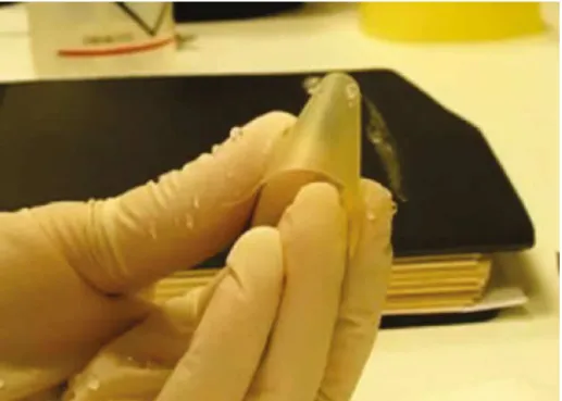
In this thesis, we prepared superhydrophobic-superhydrophilic, antireflective-antifogging, anticorrosion and antiicing (ice retarding) functional surfaces us-ing organically modified silica and its nano-composites in thin film form. Methyltrimethoxysilane (MTMS) is used in the synthesis of all films due to its intrinsically hydrophobic nature. This monomer is found to enable porous film formation without any modifications at ambient temperature and pressure. Su-perhydrophobic ormosil aerogel films with water contact angles reaching 179.9◦
and porosity of 86 % have been prepared using phase separated colloidal suspen-sions of MTMS, which exhibited flexibility, thermal stability and superhydrophilic transition after annealing at 600◦C. Antireflective films with high mechanical
sta-bility are prepared from co-condensation of MTMS with tetraethylorthosilicate monomer, which exhibited transmission as high as 99.6 % with flexibility and transition to antifogging after annealing at 600 ◦C. Anticorrosion films for glass
surfaces have been prepared by encapsulation of ZnO and ZrO2 nanoparticles to
yield nano-composites of porous and nonporous ormosil films, which resulted in four times less corrosion compared to bare glass and acts as a barrier layer for
v
corrosion of glass substrates against alkaline corrosion. In formation of antiicing coatings various combinations of ormosil films mentioned are used and correlation between contact angle, stability of contact angle against cooling, surface rough-ness and freezing times are investigated. Compared to bare glass, freezing times are increased two order of magnitudes.
Keywords: Nanomaterials, functional surfaces, ormosil, thin film, aerogel, sol-gel, anticorrosion, antiicing, superhydrophobic, antireflective.
H¨ulya Buduno˘glu
Malzeme Bilimi ve Nanoteknoloji, Doktora Tez Y¨oneticisi: Do¸c. Dr. Mehmet Bayındır
A˘gustos, 2012
Organik olarak modifiye edilmi¸s silikalar (ormosiller) organik ve inorganiklerin birle¸simi ¨ozelliklerinden dolayı e¸ssiz malzemelerdir. Ormosiller i¸ceriklerinde sert Si-O-Si ba˘glarında azalma sa˘glayan, esnek karakter kazandıran en az bir hidrolize olmayan organik grup bulundururlar. B¨oylece ormosiller hem organiklerin es-nekli˘gini hem de inorganiklerin dayanıklılı˘gını g¨osterirler. Organik grup ormosilin fonksiyonunu belirler, b¨oylece uygun organik modifikasyonlarla ¨ozellikleri ayarlan-abilir. Ormosiller kolayca sol-jel tekni˘ginin ılıman ko¸sullarında hazırlanabilirler ve de˘gi¸sik y¨uzeylere d¨u¸s¨uk maliyetli ve basit tekniklerle uygulanabilirler.
Bu tezde s¨uperhidrofilik-s¨uperhidrofobik, ı¸sı˘gı geri yansıtmayan-bu˘gulanmayan, korozyon ¨onleyici ve buzlanma ¨onleyici (geciktirici) fonksiyonel kaplamalar, or-mosil’ler ve ince film formundaki nano-kompozitleri kullanılarak hazırlanmı¸stır. Metiltrimetoksisilan (MTMS) i¸csel hidrofobik do˘gasından dolayı b¨ut¨un filmlerin sentezinde kullanılmı¸stır. Bu monomer herhangi bir y¨uzey modifikasyonuna gerek duyulmadan, normal sıcaklık ve basın¸cta g¨ozenekli film olu¸smasını sa˘glamaktadır. Su temas a¸cıları 179.9◦’ye ula¸san ve g¨ozeneklili˘gi % 86 olan, esneklik, termal
dayanımı y¨uksek, 600◦C’de fırınlandıktan sonra s¨uperhidrofili˘ge ge¸ci¸s yapma
¨ozelli˘gine sahip s¨uperhidrofobik ormosil aerojel incefilmler faz ayrı¸sması olmu¸s MTMS kolloidal s¨uspansiyonlarından hazırlanmı¸stır. Y¨uksek mekanik dayanımı olan, % 99.6 kadar y¨uksek ı¸sık ge¸cirgenli˘gine sahip, esnek ve 600◦C’den sonra
bu˘gulanmama ¨ozelli˘gine ge¸ci¸s yapan ı¸sı˘gı geri yansıtmayan filmler MTMS ve tetraetilortosilikat’ın birlikte jelle¸smesiyle elde edilmi¸stir. Cama kıyasla d¨ort kat daha az korozyona u˘grayıp korozyona kar¸sı bariyer g¨orevi g¨orerek cam s¨ubstratı alkalin korozyonundan koruyan cam i¸cin korozyon ¨onleyici filmler
vii
ZnO ve ZrO2 nanopar¸cacıklarının g¨ozenekli ve g¨ozeneksiz ormosil film
nano-kompozitlerinin hazırlanmasıyla olu¸sturulmu¸stur. Buzlanma geciktirici kapla-maların hazırlanmasında ¸simdiye kadar bahsedilen ormosil filmerin de˘gi¸sik kom-binasyonları kullanılmı¸stır ve temas a¸cısı, temas a¸cısının so˘gutma kar¸sısında dayanıklılı˘gı, y¨uzey pr¨uzl¨ul¨u˘g¨u ve donma zamanları arasındaki ba˘gıntı ince-lenmi¸stir. Donma s¨uresi bo¸s camla kıyaslandı˘gında ormosil kaplamalarda y¨uz kattan fazla artı¸s g¨ozlemlenmi¸stir.
Anahtar s¨ozc¨ukler: Nanomalzemeler, fonksiyonel y¨uzeyler, ormosil, aerojel, sol-jel, korozyon ¨onleyici, buzlanma ¨onleyici, s¨uperhidrofobik, ı¸sı˘gı geri yansıtmayan.
I would like to express my deepest gratitude to my supervisor Assoc. Prof. Mehmet Bayındır for his invaluable guidance, support and encouragement. His experiences and guidance enabled me to develop a scientific understanding of the subject. Furthermore, he helped me to learn struggle and overcome the problems by myself, which I believe will be the best experience for the rest of my life.
I would especially like to thank Adem Yildirim, whom have helped me since beginning for his supports and friendship.
I would like to thank all my group members: Pınar Beyazkılı¸c , Bihter Da˘glar, Erol ¨Ozg¨ur, Mehmet Kanık, H¨useyin Duman, Tu˘grul C¸ . Cinkara, Tural Khudiyev, Ozan Akta¸s, Yunus C¸ etin, G¨ok¸cen B. Demirel, ˙Ibrahim Yılmaz and especially Muhammet C¸ elebi and M. Halit Dola¸s for their help during freezing time measurements. Additionally, I would like to thank my former group mem-bers: Dr. Abdullah T¨ulek, Dr. Hakan Deniz, Dr. Mecit Yaman, ¨Ozlem K¨oyl¨u Alkan, Duygu Akbulut, ¨Ozlem S¸enlik, Kemal G¨urel, Murat Celal Kılın¸c, Mert Vural, H. Esat Kondak¸cı, Reha ¨Ozalp, Yavuz N. Erta¸s, Tarık C¸ eber, Can Koral and Ahmet ¨Unal. I believe that I’m very lucky, because I had chance to meet and have fruitful discussions with all of these valuable people. I am also thankful to Deniz Kocaay for being much more than just an office mate and her helps for self cleaning photographs and videos. I also would like to thank UNAM engineers Fatih B¨uker, Semih Ya¸sar, Mustafa G¨uler, Enver Kahveci and G¨ok¸ce C¸ elik.
I wish to give my special thanks to my dear husband ˙Ibrahim Levent Buduno˘glu and my dearest daughter Ece Buduno˘glu for always loving and sup-porting me, even on my most horrible mood. Finally, I’m grateful for my parents G¨ulbahar and Bayram ¨Ozg¨ur for their encouragement, support and patience.
The financial support from T ¨UB˙ITAK, T ¨UBA and Ministry of Development are also gratefully acknowledged.
ix
Dedicated to my lovely
1 Introduction 1
2 Functional Surfaces 4
2.1 Sol-Gel Chemistry of Silica . . . 4
2.1.1 Acid Catalysed Hydrolysis . . . 5
2.1.2 Base Catalyzed Hydrolysis . . . 6
2.1.3 Acid Catalyzed Condensation . . . 6
2.1.4 Base Catalyzed Condensation . . . 7
2.1.5 Gelation and Aging . . . 7
2.2 Aerogels . . . 8
2.3 Organically Modified Silicas (ORMOSILs) . . . 9
2.4 Superhydrophobicity-Superhydrophilicity . . . 10
2.5 Antireflection . . . 12
2.6 Anticorrosion for Glass Substrates . . . 14
2.7 Antiicing Surfaces . . . 17
CONTENTS xi
3 Experimental 21
3.1 Sample Characterization . . . 21
3.1.1 Scanning Electron Microscopy (SEM) . . . 21
3.1.2 Transmission Electron Microscopy (TEM) . . . 21
3.1.3 Atomic Force Microscopy (AFM) . . . 22
3.1.4 Contact Angle Measurement System (CAM) . . . 22
3.1.5 Ellipsometeric Measurements . . . 22
3.1.6 UV-Visible Spectroscopy . . . 23
3.1.7 X-ray Photoelectron Spectroscopy (XPS) . . . 24
3.1.8 Thermal Gravimetric Analysis (TGA) . . . 24
3.1.9 Differential Scanning Calorimetry (DSC) . . . 24
3.1.10 X-Ray Diffractometer (XRD) . . . 24
3.1.11 Fourier Transform Infrared Spectroscopy (FTIR) . . . 25
3.1.12 Mechanical Stability Tests . . . 25
4 Transparent Superhydrophobic Films 26 4.1 Synthesis of Ormosil Aerogel Thin Films . . . 28
4.2 Characterization of Thin Films . . . 29
5 Antireflective Coatings from Ormosils 49 5.1 Synthesis of Antireflective Ormosil Thin Films . . . 51
6.1 Synthesis of Porous Ormosil Films . . . 74
6.2 Synthesis of Nonporous Ormosil Films . . . 74
6.3 Synthesis of ZnO Nanoparticles . . . 75
6.4 Synthesis of ZrO2 Nanoparticles . . . 75
6.5 Characterization of ZnO Containing Nano-Composites . . . 76
6.6 Characterization of ZrO2 Containing Nano-Composites . . . 86
7 Antiicing Properties of Ormosil Coatings 95 7.1 Characterization Ormosil Films in Terms of Ice Retardation . . . 96
List of Figures
2.1 Main reaction types observed for silicates. . . 5
2.2 Acid catalysed hydrolysis mechanism for alkoxysilanes. . . 6
2.3 Base catalysed hydrolysis mechanism for alkoxysilanes. . . 6
2.4 Acid catalysed condensation mechanism for alkoxysilanes. . . 7
2.5 Acid catalysed condensation mechanism for alkoxysilanes. . . 7
2.6 Illustration of relation between contact angle and surface tensions and Young’s equation. . . 10
2.7 Schematic representation of two different types of filling behavior of water on protrusions. . . 11
2.8 Schematic representation of different techniques used for prepara-tion of antireflective surfaces. . . 13
2.9 A photograph of window glass after long term corrosion by water. 15 2.10 Schematic representation of corrosion mechanism on sodium sili-cate glasses. . . 16
2.11 Energy diagram showing the formation of a homogeneous nucle-ation cite as a function of its radius. . . 18
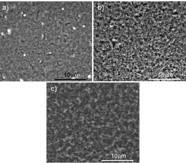
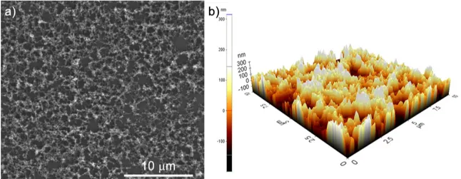
4.1 SEM images of a) Me15-a, b) Me25-a, and c) Me35-a showing the effect of changing methanol ratio on the porosity. . . 29
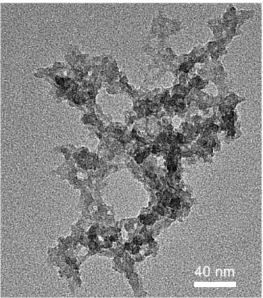
4.2 TEM micrograph of Me25 film visualizing the silica network with pores. . . 30
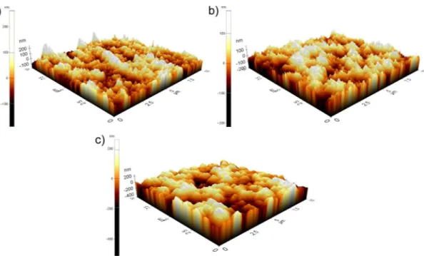
4.3 3D AFM images of a) Me15-a, b) Me25-a, and c) Me35-a showing the affect of porosity on roughness. . . 31
4.4 Photographs of a) Me15-a, b) Me25-a, and c) Me35-a taken during contact angle measurements showing how water stands on each surface, with measured values written inside the drops. . . 32
4.5 Transmission measurements of as prepared Me15 (red), Me25 (blue) and Me35 (green) with comparison to bare glass. . . 33
4.6 Photographs of a) bare glass dripped into water in comparison with, b) Me35-a coated glass. . . 35
4.7 Photographs of Me35-a film indicating the self-cleaning property a) before water pouring, and b) after cleaning with water for less than 1 s. . . 35
4.8 Rolling water droplets from Me35 coated polyethersulfone sample even when the film is bent. . . 37
4.9 SEM image of Me35-c, and b) AFM image of Me35-c showing the effect of annealing at 600◦C for 1h. . . . 38
4.10 FTIR measurements of Me35-a and Me35-c indicating the decom-position of methyl groups after annealing at 600 ◦C for 1h. . . . . 39
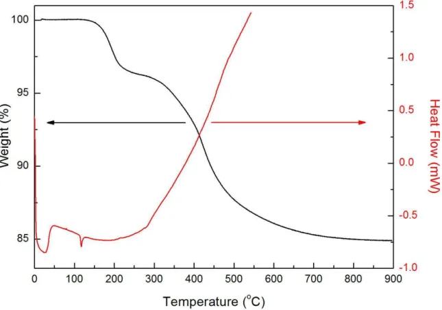
4.11 DSC and TGA measurements of Me35 sample for determination of decomposition conditions of methyl groups. . . 40
LIST OF FIGURES xv
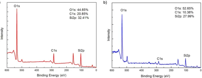
4.12 XPS results obtained from a) Me35-a and b) Me35-c indicating re-placement of surface methyl groups by hydroxyls due to annealing at 600◦C. . . . 41
4.13 Photograph of 4 µL water droplet on Me35-c indicating superhy-drophilic behavior with contact angle smaller than 5◦. . . . 42
4.14 Change of contact angle as a function of annealing temperature for 1 h annealing durations, and as a function of annealing duration at 600◦C given as inset. . . . 42
4.15 a) Photographs of Me35-a, Me35-b and Me35-c from left to right in-dicating the enhancement in transparency as a result of annealing. b) Transmission graph of Me35-a, Me35-b and Me35-c and Me15-a, Me15-b and Me15-c showing the increase in transmittance, and c) wavelength dependent refractive index measurements of Me35-a, Me35-b and Me35-c samples. . . 44
4.16 Schematic representation of dye molecules encapsulated into aero-gel structure, interacting with the TNT molecules present in air. . 45
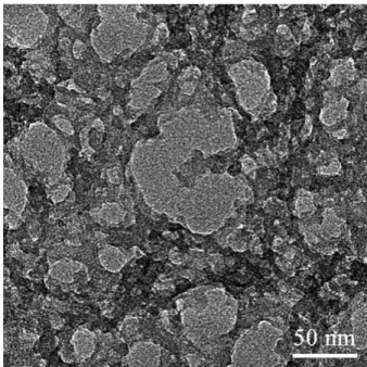
4.17 TEM image of porphyrin dye encapsulated ormosil thin film, show-ing the high nanoporosity. . . 46
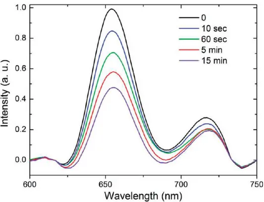
4.18 Time dependent fluorescence quenching experiment on porphyrin encapsulated ormosil. . . 47
5.1 SEM images of a) T0, b) T25, c) T60, d) T80 and e) T100 films, showing the decrease in pore sizes with increasing TEOS fraction. 52
5.2 Cross sectional SEM image of T60 film on silicon substrate with thickness around 100 nm. . . 53
5.3 TEM micrographs of a) T0, b) T25, c) T60, and d) T80 films, show-ing the skeletal structures gettshow-ing thinner with increasshow-ing fraction of TEOS, with scale bars of 100 nm. . . 54
free, transparent gel formation for hybrid compositions. . . 55
5.5 AFM images of a) T0, b) T25, c) T60, d) T80, and e) T100 films indicating hybrid films have better surface coverage with uniform pore size distribution, where T0 has pore distribution over a wide range and T100 is nonporous. . . 56
5.6 Plot showing change in average roughness of the films with respect to changing TEOS fractions. . . 57
5.7 Plot of index of refraction and percent porosity with respect to TEOS fraction, indicating increasing TEOS fraction results in de-creasing porosity. . . 59
5.8 Transmission graph of T0, T25, T60, T80 and T100 films with comparison with bare glass showing the antireflection property of hybrid films. . . 60
5.9 Transmission measurements of double side T60 coated cellulose ac-etate substrate before and after 100 bending cycles with a bending diameter of 2.5 mm. inset shows the bent CA substrate. . . 61
5.10 Photographs of hybrid ormosil coated and bare CA substrates vi-sualizing antireflective property of coatings. . . 62
5.11 For T60 film a) change of thickness with respect to dilution amount, b) change in transmission according to dilution. . . 63
5.12 XPS results of a) T0, b) T25, c) T60 and d) T80 for monitoring change in organic content. . . 64
5.13 Change of contact angle with respect to TEOS fraction, indicating the increase in hydrophilicity with increasing TEOS. . . 65
5.14 Transmission plots of T60 before (black line) and after (red line) 90 h of water dripping indicating that the film is mechanically stable. 66
LIST OF FIGURES xvii
5.15 SEM images of a) T0, b) T25, c) T60 and d) T80 films after scratch-ing with 6H, HB and 5B hardness pencils. . . 67
5.16 Affect of annealing at 600◦C for 5 min durations on contact angle
of T60 film, which ends up with transition to superhydrophilic. . . 68
5.17 Transmission plot of thick T60 film during transition to superhy-drophilic with increasing antireflectivity. . . 69
5.18 Photograph showing the antifogging property of superhydrophilic antireflective T60 film annealed at 600◦C. . . . 70
6.1 TEM micrograph showing particle sizes and crystallinity, and b) XRD plot of ZnO nanoparticles indicating Wurtzite structure. . . 76
6.2 SEM images of a-b) BPF, c-d) ZnPF, e-f) BNPF, and g-h) ZnNPF. 78
6.3 Transmission measurements of BPF and ZnPF before and after corrosion indicating some protection resulting from porous film. . 79
6.4 Transmission measurement showing the results of corrosion tests on ZnNPF and BNPF with comparison to bare glass. . . 80
6.5 Transmission measurements showing the results of corrosion tests on 450 ◦C 1h annealed ZnNPF and BNPF with comparison to
bare glass, indicating that annealed ZnNPF nano-composite can provide some extend of anticorrosion. . . 81
6.6 SEM images of 24 h corroded a-b) bare glass, c-d) ZnPF, and e-f) ZnNPF annealed 450 ◦C for 1h. . . . 82
6.7 SEM images of corroded and cleaned a) bare glass, b) ZnPF, c) BPF and d) BNPF indicating that ormosil nano-composites can protect the glass substrates from corrosion. . . 83
6.8 Transmission graphs of 24 h corroded and cleaned films, indicating that ormosil films provide glass substrate from corrosion. . . 84
layer is removed from ormosil film coated glass substrates. . . 85
6.10 TEM image of aerogel like interconnected ZrO2 nanoparticles in
amorphous state, b) XRD plot of crystalline ZrO2 nanoparticles
obtained by annealing at 500 ◦C for 1h. . . . 87
6.11 SEM images of a-b) ZrPF, c-d) ZrNPFamp, and e-f) ZrNPFxtl indicating that particle distribution is better in NPF. . . 88
6.12 Transmission measurements of BPF (blue lines) and ZrPF (red line) with comparison to bare glass for before (solid lines) and after (dashed lines) cases. . . 89
6.13 Transmission measurements of BNPF (blue lines), ZrNPFamp (green line) and ZrNPFxtl (red line) with comparison to bare glass for before (solid lines) and after (dashed lines) cases. . . 90
6.14 SEM images of a) bare glass, b) ZrPF, c) ZrNPFamp and, d) ZrNPFxtl, indicating that nano-composite films of nonporous structure are corroded less. Scale bar is the same and 4 µm for each image. . . 91
6.15 SEM images of corroded and cleaned a) bare glass, b) ZrPF, c) ZrNPFamp, and d) ZrNPFxtl with scale bar of 4 µm for each image. 92
6.16 Transmission graph of 48 h corroded and cleaned ZrO2 containing
and bare porous and nonporous films. . . 93
6.17 AFM images of corroded and cleaned a) ZrPF and b) ZrNPFxtl. . 94
7.1 Effect of roughness on the change in contact angles during cooling to -10◦C from room temperature. . . . 98
7.2 Plot of contact angle with respect to surface roughness, indicating that roughness is crucial for high water repellency. . . 99
LIST OF FIGURES xix
7.3 Freezing period of a water droplet on ormosil sample during con-tinuous cooling at -10◦C. . . 100
7.4 Photograph showing ice formation starting from side walls, through the center of the film. . . 101
7.5 Plot of contact angle with respect to freezing time, including the contact angle change values as a result of cooling. . . 102
7.6 Graph of freezing time with standard deviations with respect to average surface roughness. . . 103
7.7 Ternary diagram of roughness, freezing time and contact angle change. . . 104
4.1 Affect of composition and annealing conditions on physical prop-erties such as contact angle, roughness, refractive index and porosity. 34
4.2 Water contact angles and sliding angles for Me35 coated different substrates, which exhibited superhydrophobicity upon coating. . . 36
6.1 Table of refractive index and thickness for ZnO containing and bare porous and nonporous films. . . 77
6.2 Table of roughness values of ZnO loaded and bare porous and nonporous films, obtained from 10x10 µm2
regions. . . 86
6.3 Table showing refractive index and thickness values of ZrPF and ZrNPF. . . 87
7.1 Table of contact angle values, change in contact angle during cool-ing from 20 to -10◦C, average surface roughness, average freezing
time, and standard deviation in freezing time. . . 97
Chapter 1
Introduction
Improvements in science and technology have changed the perspective of scien-tists to the materials. It is realized that as the size of a material goes down to nanometer scale, the properties of the material drastically change. This change stems from increasing surface area compared to bulk which exhibits different properties due to its different energy. Thus surfaces started to become even more important.
Surfaces of substrates which are modified or enhanced in some properties in order to provide an extra functionality are called as functional surfaces. These kind of surfaces can be achieved either by changing the surface topography or chemistry of the substrate itself or by coating the substrate with another mate-rial which provides the functionality [1, 2]. Superhydrophobic (extremely water repellent), antireflective, antifogging, antiicing, self cleaning, antibacterial, an-tibiofouling and sensing surfaces are most commonly used functional surfaces [3, 4, 5, 6, 7]. Superhydrophobic surfaces are important for many industrial ap-plications like self-cleaning surfaces including stain-resistant textiles, self-cleaning traffic indicators, prevention of accumulation of snow on the antennas and win-dows; reducing the friction on the ship hulls and for prevention of bio-fouling [1, 8, 9]. Antireflective surfaces are commonly used in solar cells, display screens, optical filters, windows and eye-wears to eliminate reflection losses [10, 11, 12]. Antifogging surfaces are based on superhydrophilicity (extremely water liking).
they also provide self-cleaning to the surfaces they are coated but by a different mechanism compared to superhydrophobic surfaces [13, 14, 15]. Antiicing sur-faces are crucial for wind turbines and aerospace industry in addition to other application fields like antennas in order to increase efficiency and decrease dam-age generated by ice accretion [16, 17, 18]. Self-cleaning surfaces are especially important where it is hard to reach and the surface is sensitive to chemical clean-ing agents or scrubbclean-ing like solar concentrators and optical lenses [4, 19, 20]. In addition these surfaces help to eliminate the cleaning costs. Sensing surfaces are preferred because of their low cost and their fast responses against chemicals due to their high surface area compared to bulk materials [21, 22, 23]. Anticorro-sion surfaces are especially important for prevention of aqueous corroAnticorro-sion on both glasses and metal sufaces which have tendency to oxidize.
In this thesis, we combined extreme properties of aerogels with ormosils in order to obtain functional thin film coatings. We preferred to use methyltrimethoxysilane (MTMS) precursor, which has three hydrolysable groups and a hydrophobic (-CH3) group which makes it suitable for construction of
am-bient pressure dried ormosil aerogels. For obtaining ormosil thin films we initially prepared colloidal suspensions, from ultrasonically breaking of ormosil gels by di-lution with appropriate solvent. Finally obtained colloidal suspension containing porous ormosil nanoparticles were deposited on almost any surface by spin, spray or dip coating techniques. Using this method we successfully prepared flexible superhydrophobic films which can be transformed into superhydrophilic, flexi-ble and mechanically staflexi-ble antireflective films which can also be converted to antifogging films.
In addition we prepared nano-composite thin films using porous and non-porous ormosil structures for encapsulation of ZnO and ZrO2nanoparticles, which
are used for providing anticorrosion against alkaline solutions. Four times less corrosion is achieved using ormosil nano-composite thin films.
Finally, ice retardation properties of ormosil films with roughness values vary-ing from 0.8 nm to 120 nm and contact angles varyvary-ing from 30.3◦ to 179.9◦ have
CHAPTER 1. INTRODUCTION 3
been investigated for several films. Based on the findings of these results we investigated the properties dominating on the determination of freezing times.
This thesis is organized as follows: in Chapter 2 we provide theoretical pre-liminaries that are necessary for development and understanding of thesis work, addressing the terms and concepts like hydrophobicity, antireflection, corrosion and icing. Chapter 3 provides detailed instrumental techniques used for analysis of the structures synthesized. In chapter 4, we present our works on synthesis and characterization of highly transparent, flexible and thermally stable ormosil aerogel thin films. Their change form superhydrophobic to superhydrophilic is investigated in detail. Chapter 5 presents preparation and characterization of flexible, mechanically stable and antireflective ormosil thin films. The control mechanisms on thickness and porosity are visualized. Moreover, their transition to antifogging in anddition to antireflection by annealing is characterized. In Chapter 6, preparation of nanoparticle embedded ormosil nano-composite films are prepared and their anticorrosion characteristics are examined against alkaline corrosion for glass substrates. In chapter 7, antiicing properties of ormosil films with contact angles and roughness varying from high to low are examined and compared to bare glass, two order of magnitudes enhancement in freezing time is observed. Chapter 8 we conclude the subjects investigated and give potential application areas.
Theoretical Background of
Functional Surfaces
2.1
Sol-Gel Chemistry of Silica
Sol is the colloidal suspension of solid particles freely moving inside the liquid, where gel is the macroscopically extended version of these particles, linked each other throughout the solution [24]. As the name implies, sol-gel technique is based on the formation of an initial sol which have possible sites for cross linking, then formation of a gel using this colloidal suspension. As silicon is one of the most abundant materials in nature, sol-gel chemistry of silicates are investigated in detail. There are examples of naturally occurring silicate gels as in case in opal, which is composed of amorphous silica particles glued by silicate gel [25]. Silicate gels are obtained by hydrolysis and condensation reactions of silicate monomers. Most commonly used silicate monomers are tetraalkoxysilane precursors such as tetraethoxysilane (TEOS) or tetramethoxysilane (TMOS) [26]. There are three reaction types in silicates in the functional group level as shown in Figure 2.1.
As reactions given in Figure 2.1 indicate, it is possible to obtain silicate gels in the absence of catalysts. On the other hand, without a catalyst hydrolysis rate is very low, and it is not possible to fully hydrolyze the precursors. Similarly, for
CHAPTER 2. FUNCTIONAL SURFACES 5
Figure 2.1: Main reaction types observed for silicates.
complete condensation elevated temperatures would be required. Thus acids or bases are used for catalyzing hydrolysis and condensation of silicates [24].
2.1.1
Acid Catalysed Hydrolysis
In acid catalyzed hydrolysis of alkoxysilanes, initially an alkoxide group is proto-nated. Protonation results in withdrawal of electron density from silicon, enabling it to be attacked by water molecules present in the environment. Back side attack of water results in reduction of positive charge on protonated alkoxide. Reaction takes place with leaving of the alcohol and inversion of the tetrahedron of silica as shown in Figure 2.2. Mineral acids, acetic acid, hydrofluoric acid and potassium fluoride are highly used for hydrolysis of silicates due to their fast and effective reactions [24, 27].
Figure 2.2: Acid catalysed hydrolysis mechanism for alkoxysilanes.
2.1.2
Base Catalyzed Hydrolysis
Figure 2.3: Base catalysed hydrolysis mechanism for alkoxysilanes.
Under basic conditions, free hydroxyl ions rapidly form inside the reaction mixture which can attack the silicon atom from back side. Hydroxyl replaces alkoxide anion with inversion of the tetrahedron of silica, as given schematically in Figure 2.3. Potassium hydroxide, ammonium hydroxide and amines are com-monly used for this purpose [28].
2.1.3
Acid Catalyzed Condensation
Acid catalyzed condensation reaction is initiated with formation of a protonated silanol, of which silicon becomes more electrophilic. Higher electrophilicity makes silicon of protonated silanol more susceptible to nucleophilic attacks by neutral silanols. Reaction between electrophilic and neutral silanol ends with formation of Si-O-Si bridge and hydronium ion, Figure 2.4
CHAPTER 2. FUNCTIONAL SURFACES 7
Figure 2.4: Acid catalysed condensation mechanism for alkoxysilanes.
2.1.4
Base Catalyzed Condensation
Figure 2.5: Acid catalysed condensation mechanism for alkoxysilanes.
Most widely accepted base catalyzed condensation mechanism is based on the attack of a deprotonated silanol to a neutral silanol. After binding of the negatively charged oxygen of the charged silanol, a hydroxyl group is kicked out from the initially neutral silanol and Si-O-Si bridge is formed.
2.1.5
Gelation and Aging
Gelation takes place with the condensation reactions. As the number of Si-O-Si bonds increases and the domain size of these condensed molecules increases, the viscosity of the reaction mixture increases. When the size of cross linked molecules reaches all solution, the gel is formed. Gel can be defined as a contin-uous, linked solid network filled with liquid. The instance at which the last bond is formed is called as the gel point, but it is not easily measurable [24, 29]. Bond
rotations inside the gel; enabling formation of new bonds between species in close proximity. In addition, tiny moving sol particles can also attach themselves to the gel network. This time duration of additional condensation is called as aging, which changes the final properties of the formed gel network due to continuing condensation and hydrolysis reactions taking place [24].
2.2
Aerogels
Most of the functional surfaces either require designed surface roughness or poros-ity. Silica aerogels are the lightest solids ever synthesized due to their extremely porous structure [30]. The high porosity is a result of the three dimensional struc-ture of aerogels which is composed of SiO2 nanospheres of a few nanometers in
diameter surrounded by macro and meso-pores [31]. The open structure provides aerogels with some extreme properties such as high porosity (up to 99.9 %), high surface area (1200 m2
/g), low density (0.003 g/cm3
), low thermal conductivity (0.005 W/mK) and very low index of refraction (1.01) [32, 33, 34, 35, 36]. Poten-tial applications of aerogel films are varied from being dielectric in integrated-circuits to corrosion inhibition, humidity sensors and antireflection coatings [37, 38, 39]. Synthesis of aerogels are mainly based on three steps: gel prepa-ration, gel aging and drying of the gel [40]. During the drying step, because of the high surface tension formed at the vapor-liquid interface inside the pores, the silica network can collapse. In order to prevent collapsing of the network, supercritical drying is applied using either the solvent of the gel or liquid CO2.
Recently, ambient pressure methods have been established. These techniques re-quire either modification of gel with hydrophobic groups or additional washing and aging steps to strengthen the gel network in order to minimize the capil-lary tension and additional condensation induced shrinkage [41, 42]. This phe-nomenon is known to be the spring-back effect, because during drying the gel structure initially shrinks along the drying line, then springs back to a level close to its initial volume [42]. Modification steps required at ambient drying method
CHAPTER 2. FUNCTIONAL SURFACES 9
for obtaining spring back can be eliminated by using alkyltrialkoxysilane precur-sors with hydrophobic functional groups. It is reported that ambient pressure dried silica aerogels can be synthesized using methyltrimethoxysilane monomer without applying surface modifications due to its hydrophobic nature [43].
2.3
Organically Modified Silicas (ORMOSILs)
There are many different methods used to prepare functional surfaces, but among the materials used organically modified silicas (ormosils or organosilica hybrids) have superior properties compared to inorganic silica based materials and fully organic materials. As the name implies ormosils are silicas which contain one or more non-hydrolysable organic groups. The organic moiety that silica monomers contain results a decrease in the number of rigid Si-O-Si bonds and introduces a flexible character to the structure . Thus ormosils have unique properties such as flexibility and atmospheric stability which cannot be afforded neither by organics nor inorganics alone. More over their physical and chemical properties can be tuned by varying the organic groups of the silica monomers [44]. Organic groups can further be used to adjust the surface properties such as polarity, hydropho-bicity, and catalytic, optical and electronic activities [45, 46, 47].
Ormosils can be easily obtained under mild conditions using sol-gel techniques and for preparation of functional surfaces they can be applied to substrates us-ing simple techniques like spin, dip or spray coatus-ing techniques which enables large area fabrication. On the other hand most of the functional surfaces are obtained using chemical vapor deposition, layer by layer deposition, plasma etch-ing, electrospinning and lithographic methods which are time, capital and energy consuming [11, 48, 49, 50, 51, 52, 53, 54].
In Greek hydro means water and phobos means fear, thus hydrophobicity means water repellant. Behaviors of solid surfaces against liquids are defined accord-ing to the contact angle of liquid when it is suspended over the solid surface. When the applied liquid is water, this angle is defined to be water contact an-gle, which is formed between three phase boundary; where liquid, solid and gas intersect as illustrated in Figure 2.6. If the contact angle is higher than 150◦
and sliding angle is smaller than 10◦, then the surface is called to be
superhy-drophobic where surfaces with contact angle smaller than 10◦ are encountered as
superhydrophilic [8].
Figure 2.6: Illustration of relation between contact angle and surface tensions and Young’s equation.
Even though Aristotle, Archimedes, and Galileo mentioned wetting phe-nomenon, Thomas Young is the person who defined the contact angle [55]. Ac-cording to Youngs equation given in Figure 2.6 contact angle, given as θ is directly related to surface tensions between solid-vapor (γSV), solid-liquid (γSL)
and liquid-vapor (γLV) [56]. However this equation is not valid for rough
sur-faces as it does not include any roughness parameter where roughness enhances hydrophobicity in high extend. It is not possible to obtain a surface with wa-ter contact angle higher than 120◦ without introducing roughness to the surface
[57, 58]. Rough surfaces are categorized according to filling behavior of water between the protrusions on the surface, given in Figure 2.7. If the water fills the
CHAPTER 2. FUNCTIONAL SURFACES 11
space between protrusions Wenzel equation needs to be used where contact angle is defined as θ’and r is the roughness factor - the ratio of actual area to the geo-metrically projected area [58]. If there is trapped air between water droplet and protrusions than Cassie-Baxter equation is applied which uses θ” for definition of contact angle and ϕ as the surface fraction of the solid [59].
cos θ0 = r(γSV − γSL
γLV
) = r cos θ, cos θ00= ϕ[(γSV − γSL
γLV
) + 1] (2.1)
Figure 2.7: Schematic representation of two different types of filling behavior of water on protrusions.
There are many examples of hydrophobic surfaces in nature which inspired humans for production of such surfaces especially due to their self cleaning prop-erty. Lotus is a very well known superhydrophobic plant existing in nature [60]. It is composed of micrometer and nanometer scaled patches, coated with a hy-drophobic wax secreted by plant. Wax on the surface decreases the surface energy to provide hydrophobicity where dual scale roughness enhances hydrophobicity providing the surface superhydrophobicity [61].
Superhydrophobic and superhydrophilic surfaces both find applications in self-cleaning with different mechanisms. In a superhydrophilic surface, the drop cov-ers the surface of the substrate as a film while sliding off it. During this sliding motion the moving film removes the dirt from the surface. However, in a su-perhydrophobic surface the droplet forms a spherical shape and while rolling on the surface it also removes the dirt particles which stick on its surface [62]. In addition to self cleaning, superhydrophobic surfaces are important for production of stain resistant textiles, prevention of snow accumulation on outdoor antennas,
taining antifogging property which is crucial especially for surgical applications, optical devices, fog free mirrors and eyewear.
2.5
Antireflection
Reflection can be defined as change in the direction of light beam when it en-counters an interface between two different media with different refractive indices, and return into the medium from which it originated. It is undesirable because reflection limits the performance of optical devices as the intensity decreases es-pecially in solar cells, optical lenses and detectors [63]. Thus in order to prevent reflection losses antireflective coatings are tried to be developed. Antireflective structures are also present in nature. Cornea of moth and some butterflies con-tains some pillar like structures which reduce reflection and increase sensitivity even in the dark [64]. There are many different approaches used for preparation of antireflective surfaces where some are based on mimicking the examples from na-ture. There are mainly four different approaches used for obtaining antireflective surfaces, which are summarized in Figure 2.8 [65].
As the reflection results due to difference in the refractive indices, first strat-egy that can be applied is using a material which has refractive index in between the indices of two mediums; air and substrate. As shown in Figure 2.8 (a), the minimum reflection from the surface is obtained when the index of the film (n1) is chosen as n1 = √n2n0 where n0 and n2 are refractive indices of the first
and second medium respectively. In this method it is also important to provide destructive interference between the beams reflected from the interfaces of first medium to film and film to second medium. This condition is provided when the thickness of the antireflective film is equal to λ/4 where λ is the wavelength of the incident beam, thus reflected beams from coating and substrate surfaces destructively interfere due to λ/2 phase difference. When the glass is the sub-strate of interest the optimum value of refractive index is approximately 1.22 for monolayer coatings. Normally materials with such low refractive indices are not
CHAPTER 2. FUNCTIONAL SURFACES 13
present. In order to decrease refractive index, porosity needs to be introduced into the material [66]. The amount of the porosity introduced into the material can be calculated using equation:
π= nN − nD nN − nA
(2.2)
where π is percent porosity, nN, nD and nAare refractive indices of nonporous
film and porous film from same material, and air respectively [37]. Instead of using a single layer with a constant refractive index, a material with gradually decreasing refractive index would result in better antireflective effect. Another method shown in Figure 2.8 (c) is using different coatings on top of each other in order to provide graded index structure. In this method the top layer has the lowest refractive index and as the layer gets closer to the surface its refractive index increases. Graded structure provides antireflection in a broad band of wavelengths where homogeneous monolayer structure (Figure 2.8(a)) works with highest efficiency for a narrow spectrum.
Figure 2.8: Schematic representation of different techniques used for preparation of antireflective surfaces.
in order to introduce some air gaps to decrease effective refractive index on the surface of the substrate, Figure 2.8(b). Such patterns can be easily obtained using photolithography or ICP etching techniques. Similar to structure obtained in Figure 2.8 (a), these structures also work most efficiently in a small range of wavelengths. Broad band antireflection graded index structures can be obtained by generation of bigger the air gaps on the outer surface and smaller gap as you go deeper in the material, Figure 2.8 (d). Such graded index patterns can be obtained using reactive ion etching (RIE) or glancing angle deposition techniques [67, 68].
Antireflective films can be easily obtained on rigid and durable commonly used substrates like glass and silicon by glancing angle deposition, reactive ion etch-ing, patternetch-ing, phase separation of polymers [61, 63, 65, 66]. However, current technology requires production of antireflective surfaces on flexible substrates.
2.6
Anticorrosion for Glass Substrates
Silicate glasses are highly used in household, storage, cookware, windows and many different applications due to its properties such as long term stability com-pared to most other materials, easy production, low cost and fine appearance. Even though silicate glasses are resistive against many chemicals, they can cor-rode simply by exposure of water. Furthermore, silicate glasses are known to be hydrophilic, which makes them attract water even from the humidity of the atmosphere. The water layer spreading on top of the glass causes corrosion on glass by various mechanisms. One of these mechanisms is based on diffusion of hydroxonium ions, present on the water layer, into the glass network and ion exchange between the protons and alkali network modifiers such as sodium ions leaving behind silanol groups [69]. This is an example of acidic corrosion ob-served on glass. Especially hydrofluoric acid and hot concentrated phosphoric acid are known to corrode silicate glass effectively. Another type of corrosion on
CHAPTER 2. FUNCTIONAL SURFACES 15
glass is based on high alkaline ion concentration, where this causes the dissolu-tion of silicate itself [70]. This is the most common reason of corrosion of glasses because alkaline corrosion acts at a constant rate without reaching saturation and as the temperature increases its rate of dissolution also increases [71]. Even though the corrosion rate is low at ambient conditions, in long term corrosion due to humidity causes an undesired, opaque appearance on glass surface, as shown in Figure 2.9 [72].
Figure 2.9: A photograph of window glass after long term corrosion by water.
Schematic representation of dissolution and corrosion mechanism of sodium silicate glasses in the presence of water is shown in Figure 2.10, including the chemical changes taking place [73]. In the first case instantaneous establishment of electrochemical equilibrium takes place, which enables ion exchange between the sodium inside the sub-surface and hydrogen in the solution phases, shown in case 2. Case 3 summarizes the fast transportation of sodium and hydrogen ions, and molecular water over the sub-surface zone to solution phase. In case 4, initially formed silanol groups condensate in order to form a gel network, where in case 5 an opposite reaction takes place resulting in dissolution of silica structure [74].
Figure 2.10: Schematic representation of corrosion mechanism on sodium silicate glasses.
In industry, most of the glass produced is in the flat glass form, which is the common window glass. Once produced, reaching of the products to the consumer can take 1-2 years depending on the demand. It is known that these warehouses do not provide well proof from humidity, thus glasses can get corroded even before being sold. Never the less, they also get exposed to humidity when they are sold. In addition to flat glasses, fiber glasses used as reinforcing materials in cement are also exposed to alkaline environments, which also need protection. In order to overcome corrosion of glass, there are several techniques. Dealkalization is the most common technique used to prevent corrosion of glass surfaces. In this technique, alkali ions are removed from the outermost layer of the glass by
CHAPTER 2. FUNCTIONAL SURFACES 17
chemical treatment. Thus the layer which has lack of alkali ions, act as a barrier layer for diffusion of other ions from the bulk of the material. This method requires use of elevated temperatures (650 ◦C or higher) and sulfur or fluorine
containing compounds [74]. Due to its high cost, this technique is not preferred for flat glass applications. Another way of protecting silicate glasses against corrosion is using corrosion inhibition films. Materials such as titanium dioxide and zirconium dioxide are known to be resistive against alkaline corrosion and are used for thin film production by incorporation into silica structure [75]. ZnO is also shown to be corrosion resistant for steel in salty water when incorporated into epoxy coating, which is also a candidate for production of anticorrosive thin films for glass substrates [76].
2.7
Antiicing Surfaces
Ice formation is an important problem especially in cold regions due to its unde-sired results such as higher energy consumption, serious risk of falling on aircrafts, damages in power transmission lines, decreasing efficiency of wind turbines [77]. There are mainly three types of icing mechanism: in cloud icing, precipitation and frost [18]. Former one takes place when a supercooled water droplet meets a cold surface which has temperature below freezing point (0 ◦C). In the case of
precipitation, as the name implies, initially precipitated particles like snow or rain hit the surface below freezing point. On the other hand frost is direct formation of ice on solid surface by solidification of water vapour up on impact.
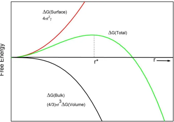
In order to obtain a better understanding of the icing, one needs to investigate the thermodynamic equilibrium of ice formation. As water is cooled down from its freezing temperature, formation of solid phase becomes thermodynamically favourable because free energy of solid is smaller than free energy of liquid below freezing temperature. However, formation of solid nuclei inside the liquid requires generation of a solid surface. Thus there will be a positive free energy related to formation of this new area of solid, which acts as a barrier to the formation of solid nuclei [78]. Inside the liquid which is cooled under its freezing point, nuclei
Figure 2.11: Energy diagram showing the formation of a homogeneous nucleation cite as a function of its radius.
instantaneously form and disappear due to random addition and subtraction of atoms. If the size of these nuclei reaches r* (critical size of nucleation), then it continues growing, because after critical size of nucleation the energy barrier due to formation of a new surface is exceeded. The free energy of formation of a solid nucleus inside the liquid is shown in Figure 2.11 with green line. Free energy required for formation of a new surface is given in red and formation of a solid volume is in black. The amount of extra cooling from the freezing temperature of a liquid is defined as supercooling. In order to find actual homogeneous nucle-ation, gravitation free conditions are applied to small volumes of liquids and the supercooling required for freezing is determined. It is reported the water freezes at around -37◦C under this conditions [79].
As we keep liquids in containers, we do not observe such high amount of supercooling. The walls of containers act as heterogeneous nucleation sites for
CHAPTER 2. FUNCTIONAL SURFACES 19
liquids, for which the energy barrier is much smaller. During the formation of solid-container interface, initially existing liquid-container interface is destructed, which results in energy release. Free energy change required for homogeneous nucleation is given by ∆Ghomo = − 4 3πr 3 ∆GB+ 4πr 2 γSL (2.3)
where r is the radius of nucleus, ∆GB is difference in free energies of liquid
and solid at that temperature and γSL is the surface tension between solid and
liquid. On the other hand, free energy required for heterogeneous nucleation is given by
∆Ghetero= ∆Ghomof(θ) (2.4)
where f (θ) is a function of contact angle (θ) given by
f(θ) = 1 2− 3 4cos(θ) + 1 4cos 3 (θ) (2.5)
thus the barrier energy of the heterogeneous nucleation is directly related to the contact angle of the liquid on the container surface [77].
Formation of ice on a surface can be prevented either using energy consuming active methods like resistance heating, blowing hot air or by passive methods like application of antiicing coatings [80]. It is not possible to completely prevent formation of ice; however by application of suitable coatings the freezing time can be elongated. Elongated freezing time increases the probability of removal of the drop from the surface before freezing. One strategy is using superhydrophobic surfaces as antiicing coatings. Contact angle dependent function given for hetero-geneous nucleation indicates that, as the contact angle increases, the nucleation barrier also increases. However this term is independent of the roughness, which can also affect freezing acting as a dislocation. Most of the available literature
Chapter 3
Experimental
3.1
Sample Characterization
3.1.1
Scanning Electron Microscopy (SEM)
Microstructural observations of the thin films were carried out using an environ-mental scanning electron microscope and a scanning electron microscope; E-SEM, Quanta 200F, FEI and NanoSEM, Nova, FEI on ultra-high resolution mode with a Helix detector respectively. In both, low vacuum conditions are used without application of any conductive coatings in order to directly observe the surfaces, operated at 5mm separation with 5 kV and around 0.98 Torr.
3.1.2
Transmission Electron Microscopy (TEM)
The skeletal and porous structure of the ormosil colloids, sizes and the structure of nanoparticles were visualized by bright-field images with a transmission electron microscope;TEM, Tecnai G2 F30, FEI operated at 200 kV. TEM samples are prepared by placing a drop of colloidal suspension used for film preparation on holey carbon coated copper grid or by scratching an already prepared film and
3.1.3
Atomic Force Microscopy (AFM)
The surface roughness and the topography of the films prepared on glass sub-strates were analysed using an atomic force microscope; AFM, XE-100E, PSIA in non-contact mode.
3.1.4
Contact Angle Measurement System (CAM)
A contact angle meter, OCA 30, Dataphysics, was used to measure the water contact angles of the prepared surfaces. Water droplets of 4 µL volume were used and normal fitting is applied for contact angles smaller than 120◦ where
Laplace-Young fitting was applied for highly hydrophobic samples.
Temperature dependent contact angle measurements were performed using CCD camera of the CAM system in corporation to homemade cooling system composed of two Peltier coolers placed on each other, both with the cold side up. In addition, these coolers are placed on top of an aluminum cooling plate with two computer fanners. A multi-input temperature controller is used for adjusting the temperature and temperature is controlled with help of a small thermocou-ple, placed in contact with examined sample by using a heat conducting silicon paste. Same system is also used for freezing time measurements by adjusting the temperature to -10◦C.
3.1.5
Ellipsometeric Measurements
Thickness and spectroscopic refractive index measurements were obtained by an Ellipsometer, V-Vase, J. A. Woollam. The measurements are performed in the range of 400 to 1200 nm. The experimental results were fitted by using Cauchy
CHAPTER 3. EXPERIMENTAL 23
Figure 3.1: Home-made temperature controlled cooling system.
model as:
n(λ) = A + B λ2 +
C
λ4 (3.1)
where, n is refractive index, A (dimensionless), B (µm2
) and C (µm4
) are Cauchy parameters.
3.1.6
UV-Visible Spectroscopy
UV-vis spectroscopy is used for monitoring the transmittance of the prepared films on glass and cellulose acetate substrates and for monitoring the corrosion of the substrates. UV-Vis spectra were recorded using Varian Carry100 spectropho-tometer between the 300 and 800 nm in transmission mode.
Chemical analysis of the surface was performed using X-ray photoelectron spec-troscopy (XPS), K-Alpha, Thermo Scientific. XPS measurements were performed on the slightly etched (clean) surfaces of the examined surfaces. The data was col-lected at survey mode while flood gun was operating in order to prevent charging of the surfaces.
3.1.8
Thermal Gravimetric Analysis (TGA)
Detailed chemical analyses were performed using thermal gravimetric analysis (TGA), Q500, TA Instruments. TGA measures the weight of the sample under constant heating. This way, the change on the weight of the sample can be investigated on the basis of temperature, enabling to observe decompositions. Measurements are conducted under the flow of oxygen.
3.1.9
Differential Scanning Calorimetry (DSC)
Phase and chemical changes in the samples were monitored using differential scanning calorimeter (DSC), Q2000, TA Instruments. Sample is placed in an aluminum crucible and placed into instrument together with an empty crucible. Device measures how much energy is required to increase the temperature of both crucibles 1 ◦C using the empty crucible as reference. This way, changes in the
heat capacity are monitored as a function of temperature.
3.1.10
X-Ray Diffractometer (XRD)
X-ray diffractometer (XRD) Xpert Pro MPD, Panalitical is used for examining the crystallinity of the synthesized ZnO and ZrO2 nanoparticles.
CHAPTER 3. EXPERIMENTAL 25
3.1.11
Fourier Transform Infrared Spectroscopy (FTIR)
Functional groups were on the prepared samples were characterized using a Fourier transform infrared spectrometer (FTIR), Vertex 70, Bruker. The FTIR measurement samples are prepared by dispersing small portions of synthesized films into KBr and preparation of pellets by compression under high pressure. Bare KBr pellets are used for baseline measurements.
3.1.12
Mechanical Stability Tests
Mechanical stability of the prepared samples were tested using different tech-niques as water dripping, adhesive tape testing and pencil hardness (scratching) tests [86, 87, 88, 89, 90]. In water dripping test films were placed with an incli-nation of 45◦ and 30 cm apart from a source of tap water. Then water droplets
of approximately 100 µL start to fall at a rate of one drop per second at least for 24 h. After the test, the change in the film can be monitored by SEM, CAM or transmission measurements.
In adhesive tape test a piece of tape is pressed on the coated surface with a force around 10 kPa, and then peeled off. The stability of the film on the substrate surface is monitored comparing the amount of the film initially on the substrate and after the test.
Pencil hardness test is performed by scratching the films with approximately 1 MPa of pressires with pencils of varying hardnesses in the range of 6H to 8B. The formation of scratches is then monitored using SEM.
Synthesis and Characterization
of Highly Transparent,
Flexible, and Thermally Stable
Superhydrophobic Ormosil
Aerogel Thin Films
Superhydrophobic surfaces with water contact angles larger than 150◦and sliding
angles smaller than 10◦ have many potential applications. These fields of
applica-tions are both related to their stability against water and moisture, and dirt due to self cleaning properties [8, 9]. It is known that for obtaining superhydrophobic-ity or superhydrophilicsuperhydrophobic-ity, surface needs to have low surface energy in addition to high surface roughness [58]. Fluorocarbons are known to have low surface energy values, where lowest surface energy is measured for regularly aligned hexagonal -CF3 surfaces is 6.7 mJ/m
2
[57]. Without surface roughness maximum achievable contact angle cannot exceed 120◦ [58]. Nature has combined low surface energy
and high roughness in lotus leaf. Lotus leaves are combined of micrometer and
CHAPTER 4. TRANSPARENT SUPERHYDROPHOBIC FILMS 27
nanometer-scaled patches coated by 1 nm thick hydrophobic layer [4]. High sur-face roughness due to dual scale roughness enables trapping of air below the wa-ter droplets, which helps the rolling of droplets easily, resulting in well designed superhydrophobic surfaces. Superhydrophobic films established up to now are mainly based on methylchlorosilanes, fluoroalkylsilanes, SiO2 nanoparticles
em-baded into polymers, binary polymer brushes, ZnO nanorods [91, 92, 93, 94, 95]. On the other hand, aerogel structures are suitable candidates for rough film pro-duction due to their highly porous structure. Even though aerogel propro-duction is mainly done by critical point drying (at elevated temperatures and pressures), recently ambient pressure drying techniques are developed by modification of the gel structure in order to minimize capillary tension [42, 43]. Ormosils are known to exhibit superior properties compared to both organics and inorganics such as long term atmospheric stability and flexibility. Furthermore it is possible to tune the physical properties of ormosils by changing the organic functional groups [44]. Several ormosil superhydrophobic films have been reported up to date using elec-trospinning, vapor deposition and co-condensation techniques, where some have lack of transparency, some does not have good porosity and thickness control, and some needs pre- or post treatments [56, 96, 97, 98, 99].
In this chapter, we report synthesis and characterization of highly transparent, flexible and thermally stable ormosil aerogel thin films using methyltrimethoxysi-lane (MTMS) precursor using sol gel technique [100]. Ormosil films are obtained without any surface modifications as a result of intrinsically hydrophobic nature of monomer. Produced aerogel thin films contain both micrometer and nanometer scaled roughness similar to lotus leaves, allowing air to be trapped between the water droplet and the film surface. The film transparency is an important issue in terms of its technological applications. Although roughness enhances superhy-drophobicity, it diminishes the transparency when it is higher than 100 nm result-ing in the scatterresult-ing of light [8]. Even though MTMS precursor results in opaque gels, the produced thin films are highly transparent. Superhydrophobic samples are observed to exhibit self cleaning properties. They can be easily cleaned sim-ply by rinsing with water after contaminattion with nanoparticles. The contact
hydrophobicity to superhydrophilicity with water contact angles smaller than 5◦.
During the change through superhydrophilic character, the transparency of the films further increases with decreasing surface roughness due to change of skeletal structure from ormosil to silica.
4.1
Synthesis of Ormosil Aerogel Thin Films
For the production of superhydrophobic ormosil aerogel thin films methyltrimethoxysi-lane monomer is used for its nonhydrolyzable, fuctional methyl group. Reaction is proceeded through two steps, acid catalyzed hydrolysis and base catalyzed con-densation mechanism. Methyltrimethoxysilane (MTMS), methanol, oxalic acid, and ammonium hydroxide (26 %) were used as purchased. Initially 1mL of MTMS is dissolved in 9.74 mL methanol (for obtaining 1:35 mol fraction of MTMS: methanol, for 1:25 and 1:15 fractions 6.96 and 4.17 mL methanol is used respec-tively). 0.5 mL 0.001 M oxalic acid solution was added into reaction mixture and stirred for 30 min. After hydrolysis at ambient temperature for 24 h, 0.4 mL ammonium hydroxide solution dissolved in 0.21 mL water is slowly added in to reaction mixture and further stirred for 15 minutes. With addition of base, condensation reactions starts and gel forms within 24 hours of rest. The obtained gel is further aged for 24 hours, thus gelation and aging takes 2 days.
Thin films are obtained by ultrasonically breaking the gel structure, using a liquid homogenizer, into colloidal nanoparticles [42] and diluting the suspension. 10 mL of methanol is used for dilution as it is the reaction solvent, and gel is sonicated at 20 W power for 45 s. Obtained colloidal suspensions are suitable for dip, spin and spray coating techniques. For obtaining homogeneous and con-trollable thickness values, we preferentially used spin coating at 2000 rpm for 45 s.
The prepared films are named as the number in the abbreviation (Me35-a) in-dicating the mol fraction of methanol and the letter following the dash inin-dicating
CHAPTER 4. TRANSPARENT SUPERHYDROPHOBIC FILMS 29
Figure 4.1: SEM images of a) Me15-a, b) Me25-a, and c) Me35-a showing the effect of changing methanol ratio on the porosity.
the heat treatment condition. In order to change physical and chemical properties of the films, thermal annealing is applied. Letter a stands for asprepared film, b and c for 450 and 600 ◦C annealing for 1 h durations.
4.2
Characterization of Thin Films
Surface morphologies of asprepared ormosil aerogel thin films with three different methanol fractions (15, 25 and 3) are investigated using SEM, Figure 4.1. SEM
Figure 4.2: TEM micrograph of Me25 film visualizing the silica network with pores.
micrographs reveal that all films are composed of highly porous structure. On the other hand, comparison of films indicates that gel prepared with lower fraction of methanol, Me15 (Figure 4.1-a)), has a denser structure with smaller pores, where Me35 has more micrometer sized holes (Figure 4.1-c)). As expected Me25 exhibits an intermediate pore character (Figure 4.1-b)) compared to Me15 and Me35.
Skeletal structure of the Me25-a is visualized using TEM micrograph, given in Figure 4.2. It is seen that the aerogel structure is composed of approximately 20 nm sized ormosil clusters, interconnected to each other and surrounded by pores. Films are composed from interconnection of sub-micrometer sized clusters, obtained from sonication of gel structure.
CHAPTER 4. TRANSPARENT SUPERHYDROPHOBIC FILMS 31
Figure 4.3: 3D AFM images of a) Me15-a, b) Me25-a, and c) Me35-a showing the affect of porosity on roughness.
coatings to be transparent. Both SEM images and TEM micrographs reveal that films are highly porous with pore sizes varying from nanometers to micrometer scale, which would result in high surface roughness required for superhydrophobic-ity. However, high surface roughness enhancing the superhydrophobicity lowers the transparency by scattering the light, when the roughness is higher than 100 nm [8, 12]. Surface topography of the films is investigated using AFM technique. 10x10 µm2
regions scanned at non-contact mode are shown in Figure 4.3. From AFM images, it can be seen that all films have high roughness. Average sur-face roughness measurements have also been obtained from AFM measurements. Average surface roughness of asprepared Me15 and Me25 have been found to be around 40 nm, where this value is around 120 nm for Me35 film.
MTMS monomer is known to result in superhydrophobic and flexible bulk aerogels when supercritical drying is applied due to hydrophobic methyl groups present in the monomer which are directed through the surface [101]. In this work, we also used MTMS aerogel network structure with high enough porosity
Figure 4.4: Photographs of a) Me15-a, b) Me25-a, and c) Me35-a taken during contact angle measurements showing how water stands on each surface, with measured values written inside the drops.
and roughness, in thin film form. In order to examine how water droplet stands on the surface, we used a contact angle measuring system. Sessile drop technique is applied. Water droplets of 4 µL volume are dispensed onto surfaces and contact angles were measured. Photographs taken during contact angle measuremens are shown in Figure 4.4. Contact angle of the films are found to increase with increasing fraction of the methanol used in the gel synthesis. Average contact angle of Me15-a is found to be 142.5◦, where this value is 171.1◦ for Me25-a and
178.4◦ for Me35-5 where increases up to 179.9◦ after annealing. Based on the
combined evaluation of SEM and contact angle measurements, it can be said that increasing macroporosity results in superhydrophobicity.
CHAPTER 4. TRANSPARENT SUPERHYDROPHOBIC FILMS 33
Figure 4.5: Transmission measurements of as prepared Me15 (red), Me25 (blue) and Me35 (green) with comparison to bare glass.
been measured using UV-vis spectrophotometer, given in Figure 4.5 in compari-son to uncoated glass substrate. All films are found to be highly transparent but due to higher surface roughness, Me35-a exhibits lower transparency compared to Me15-a and Me25-a as expected.
Porosity of the films are monitored using TEM, SEM and AFM techniques, but for obtaining a quantitative analysis of the fraction of porosity, we used ellipsometric refractive index measurements. For calculation of porosity we used the equation [34]:
π = 1.399 − nD 1.399 − nA
(4.1)
where π is the porosity, 1.399 is the refractive index of the nonporous film obtained from MTMS, nD is the measured refractive index and nAis the refractive
Table 4.1: Affect of composition and annealing conditions on physical properties such as contact angle, roughness, refractive index and porosity.
Film Contact Roughness Refractive Porosity Angle (◦) (nm) Index (%) Me15-a 142.5 ± 1 39 1.16 60 Me15-b 170.4 ± 4.3 51 1.09 78 Me25-a 171.1 ± 2 41 1.16 59 Me25-b 164.8 ± 3.2 40 1.09 78 Me35-a 178.4 ± 1.5 120 1.10 75 Me35-b 179.5 ± 0.4 86 1.08 80 Me35-c < 5 67 1.05 88
index of the air. Refractive index values of Me15-a and Me25-a are found to be 1.16, where it is found to be 1.10 for Me35-a indicating higher porosity of Me35 films. Porosity values for asprepared films are found to be 60 % for Me15 and 59 % for 25 films, where it is 75 % for Me35. Thicknesses of the asprepared films are also measured to be 550, 800 and 680 nm respectively for Me15, Me25 and Me35 using an ellipsometer.
Physical properties of the ormosil aerogel thin films are summarized in Ta-ble 4.1 based on their contact angles, roughness, refractive indices and porosity. Based on the evaluation of asprepared films (Me15-a, Me25-a and Me35-a), it can be concluded that lower mol fraction of methanol containing gels results in films with closer packing and lower porosity in addition to smaller average roughness. Similarly, contact angle is found to increase with increasing methanol fraction.
Annealing at 450 ◦C for 1h results in decrease in refractive indices with
en-hancement in porosity for all samples (Me15-b, Me25-b and Me35-b). This change is related to removal of some unreacted species trapped inside the gel structure during the heat treatment. In addition roughness is observed to generally de-crease and contact angles inde-crease due to removal of unreacted silanol groups during annealing at 450 ◦C [102]. Me35-b is found to exhibit contact angles
as high as 179.9◦. On the other hand, when it is annealed at 600 ◦C for 1h it
CHAPTER 4. TRANSPARENT SUPERHYDROPHOBIC FILMS 35
Figure 4.6: Photographs of a) bare glass dripped into water in comparison with, b) Me35-a coated glass.
Figure 4.7: Photographs of Me35-a film indicating the self-cleaning property a) before water pouring, and b) after cleaning with water for less than 1 s.