Analysis of Input Impedance and Mutual Coupling
of Microstrip Antennas on Multilayered Circular
Cylinders Using Closed-Form Green’s Function
Representations
Sakir Karan and Vakur B. Ertürk, Member, IEEE
Abstract—Closed-form Green’s function (CFGF)
representa-tions for cylindrically stratified media are developed and used in conjunction with a Galerkin method of moments (MoM) in the space domain for the analysis of microstrip antennas on multilayered cir-cular cylinders. An attachment mode is used in the MoM solution procedure to accurately model the feeding of probe-fed microstrip antennas. The developed CFGF representations are modified in the source region (where two current modes can partially or fully overlap with each other during the MoM procedure) so that singu-larities can be treated analytically and hence, the proposed CFGF representations can be safely used in this region. Furthermore, accurate CFGF representations for the probe-related components (necessary for probe type excitations including the attachment mode) are obtained when the radial distance between the source and field points is electrically small or zero. Numerical results in the form of input impedance of various microstrip antennas and the mutual coupling between two antennas are presented showing good agreement when compared to the available published results as well as the results obtained from CST Microwave Studio.
Index Terms—Closed-form Green’s functions, generalized
pencil of function method, method of moments.
I. INTRODUCTION
S
EVERAL integral equation (IE) based design/analysis tools that use closed-form Green’s function (CFGF) representa-tions as the kernel of an IE have been developed for the design and rigorous analysis of printed circuit elements and/or printed antennas/arrays in planar multilayered media [1]–[3]. On the other hand, when similar printed structures are considered on multilayered cylinders (with a perfect electric conductor (PEC) forming the innermost region), most of the available IE based tools still use the conventional spectral domain or asymptotic Green’s function representations (the latter being valid for a single-layer dielectric deposited on a PEC cylinder) with limita-tions [4]–[6]. When there is only a single-layer dielectric on the PEC cylinder accurate space-domain formulations without anyManuscript received February 27, 2014; revised August 26, 2014; accepted August 29, 2014. Date of publication September 11, 2014; date of current ver-sion October 28, 2014.
S. Karan is with the Department of Electrical and Electronics Engineering, Bilkent University, TR-06800 Bilkent, Ankara, Turkey. He is also with the Aselsan Electronics Inc., Ankara, Turkey.
V. B. Ertürk is with the Department of Electrical and Electronics Engineering, Bilkent University, TR-06800 Bilkent, Ankara, Turkey.
Color versions of one or more of the figures in this paper are available online at http://ieeexplore.ieee.org.
Digital Object Identifier 10.1109/TAP.2014.2357413
limitations are available [7]–[9] allowing for a flexible discretiza-tion of the printed metalizadiscretiza-tions with a triangular surface mesh. Deficiencies on the available CFGF representations for cylindri-cally stratified media have prohibited to develop the cylindrical counterpart of the above mentioned planar procedure in spite of the fact that a wide range of military and commercial applications require such tools to investigate aforementioned antennas/arrays that conform to multilayered cylindrical host platforms.
Several studies on CFGF expressions for cylindrically strati-fied media have been reported that use either generalized pencil of function (GPOF) [10] method or rational function fitting method (RFFM) [11] with the purpose of being used in method of moments (MoM)-based codes to design and analyze mi-crostrip antennas and arrays [12]–[21]. However, early studies are useful only for radiation/scattering problems because the provided CFGF expressions in them are not valid when the radial distance between the source and field points is electrically small or zero [13]–[15]. On the other hand, to be able to use the reported CFGF expressions that are valid when in con-junction with MoM, alternative Green’s function representations are required for certain regions of the cylinder. In [16], [17], the reported CFGF expressions for the mixed potential integral equation (MPIE) are not valid along the axial line (defined as and ) of the cylinder as well as in the source region (where two current modes can partially or fully overlap with each other during the MoM procedure). [18]–[20] provided CFGF expressions valid along the axial line for both electric field integral equation (EFIE) and MPIE. However, a study that uses CFGF representations within the source region and explains the related singularity treatments has not been presented to the best of our knowledge. Therefore, alternative Green’s function representations may be necessary for the self-term related entries of the MoM matrix. Furthermore, special care is required to obtain accurate CFGF expressions for the probe-related com-ponents when is close or equal to . In [21], -related dyadic Green’s function components are provided together with some identities to obtain the corresponding closed-form expressions. However, explicit expressions are not presented. Hence, detailed probe-related CFGF representations must be provided for a more accurate feed model when investigating probe-fed microstrip antennas that requires an attachment mode.
Considering all these deficiencies, CFGF representations pre-sented in [18] have been modified leading to new CFGF ex-pressions that are used in conjunction with a Galerkin MoM in
0018-926X © 2014 IEEE. Personal use is permitted, but republication/redistribution requires IEEE permission. See http://www.ieee.org/publications_standards/publications/rights/index.html for more information.
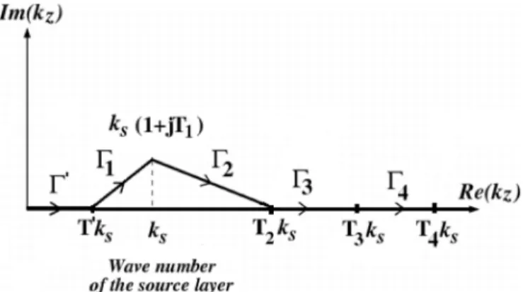
Fig. 1. Geometry of the problem. Probe-fed microstrip patch antennas on a cylindrically layered structure together with its cross-sectional view from the top.
the space domain (that uses rectangular meshes) for the analysis of probe-fed microstrip antennas on multilayered circular cylin-ders. An attachment mode, similar to the ones presented in [22] and [23] for planar stratified media, is used to more accurately model the feeding part of the antennas. These proposed CFGF representations are used everywhere including the source region as well as for the probe-related components (including the at-tachment mode) that are used to obtain an improved model for probe-fed type excitations. Therefore, the treatment of all singu-larities that appear in the source region (during the MoM anal-ysis) in addition to the axial line for all components including the probe-related ones are presented.
In Section II, the geometry and the derivation of the proposed CFGF representations are provided. This section also contains the analytical treatment of the singularities. Section III provides the MoM solution procedure. Numerical results are presented in Section IV to assess the accuracy and efficiency of the proposed CFGF representations. An time dependence, with being the angular frequency, is assumed and suppressed throughout this paper.
II. GREEN’SFUNCTIONFORMULATION
A. Geometry
Fig. 1 illustrates the geometry of two patches on an infinitely long (along the -axis) cylindrically stratified media, where a PEC cylindrical ground with a radius (denoted by ) forms the innermost region. Material layers surround the PEC region coaxially ( denotes the substrate layer; de-notes the superstrate layer, and denotes the air layer in Fig. 1). Each layer has a permittivity, permeability, thickness and radius denoted by , , and , respectively. Each patch antenna, located either on the dielectric-dielectric or di-electric-air interface, has a dimension of by along the - and -directions, respectively, and fed via a probe (depicted in the cross-sectional view of Fig. 1) at the location
and with (and ).
B. Proposed Space Domain Green’s Function Representations
Because a space domain hybrid MoM/Green’s function tech-nique is used in this paper for the analysis of probe-fed an-tennas/arrays depicted in Fig. 1, new space domain CFGF repre-sentations are developed for tangential and probe-related com-ponents, separately.
1) Tangential Components: Entries of the MoM impedance
matrix require accurate representations of the tangential com-ponents of the dyadic Green’s function due to tangential cur-rent sources for arbitrary source and field points (that mostly lie on the same interface, and in particular within the source region). However, the CFGF representations presented in [18] experience a relatively severe singularity within the source re-gion. Therefore, in [18] it was suggested that alternative Green’s function representations must be used for the entries of the MoM impedance matrix that represent the self terms. Moreover, some accuracy problems have been observed for small values despite the axial line treatment, which can also affect the ac-curacy of MoM solutions during an antenna analysis. Conse-quently, these deficiencies require modifications in the CFGF representations given in [18].
The starting point of the proposed CFGF representations for the tangential components is the spectral domain Green’s func-tion representafunc-tions, ( or or ), for given in [18] as
(1) where and , , for ; , , for and , and finally , , for . In (1) and all special cylindrical functions except the
product are inside the term and expressed in the form of ratios. Explicit expressions for are given in [18] for all tangential components. Then, as the first step, recog-nizing the Fourier series (with respect to ) and Fourier trans-form (with respect to ) relations between the spectral and space domain Green’s function representations, one can note that , , and both the
and terms in the space domain correspond to , and in the spectral domain, respectively. Therefore, the space domain Green’s function representation, , can be written as
(2) where for the , , for the
( due to reciprocity), for
cases. The term in (2) is expressed as the inverse Fourier transform (IFT) of its spectral domain counterpart as
with denoting the IFT operation, which can be per-formed in closed-form with the aid of the GPOF method if there is no numerical problems or singularities. The main advantage of expressing as (2) is to transfer these derivatives onto the basis and testing functions by performing an integration by parts twice in a Galerkin-type MoM procedure for carefully chosen basis and testing functions, which must be differentiable with respect to , , and . Note that as a result of this step, only the part appears as the space domain Green’s function re-lated term in the integrand of any mutual impedance expression ([18]) between two current modes.
Then, as explained in [18], first performing an envelope ex-traction with respect to (i.e., the cylindrical eigenmodes) to improve the efficiency and accuracy of the summation over in (3), and then performing another envelope extraction with respect to to the resultant expression to handle convergence problems in the spectral expressions for small values, is obtained as
(4) where
(5) (6) is the limiting value of when , and is the value of when (de-noted as ). The expression given by (4) yields very accu-rate results when used in the mutual impedance calculations (after performing an integration by parts twice) when there is no singularity. However, there are two cases that yield singu-larities, which should be treated. The first one manifests itself along the axial line, and the second one occurs in the source re-gion. Hence, as the next step the treatment of these singularities are given.
Axial line singularity ( , ): The argument of
the Hankel function becomes zero along the axial line ( , ). The remedy for this problem is to use the small argument approximation of the Hankel function given by
(7) where . The last term, , in (7) exhibits a logarithmic singularity when and , and yields numerical problems for small values (still ). Therefore, for the tangential components, when and is small, approximating term as
can be approximated as
(8)
where and and . Then, subtracting from in (4) and adding the subtracted part as a new term to (4), (4) becomes
(9) During the mutual impedance calculations, the added term [i.e., the third term in (9)] is calculated analytically.
Space domain singularity ( , , ): It
oc-curs within the source region, where the source and observation points overlap with each other (i.e., ), which appears in self term calculations during the MoM process. When the last term of 9 [or (4)]) that involves
exhibits an integrable singularity. Recognizing that
(10) and making use of (8), is approximated as
(11)
Then, is subtracted from in (9) and the subtracted part is added as a new term to (9). As a result becomes
(12) As seen in (12), the last two terms are related to the treatment of the space domain singularity (in addition to the axial line
singularity). In (12), the first, second and the fourth terms can now be calculated in closed-form via GPOF. They do not have any singularity. On the other hand, the third (related to axial line singularity) and the fifth (related to spatial domain singularity) terms are calculated analytically during the mutual impedance calculations.
2) Probe-Related Components ( and ): All the
cylin-drically conformal antennas, investigated in this paper, are as-sumed to be fed via a probe, where an attachment mode is used. Therefore, accurate and efficient representations of probe-re-lated components of the dyadic Green’s function are necessary to calculate the entries of the MoM voltage vector as well as the input impedance (or mutual impedance when more antennas exist). However, accurate CFGF representations for the probe-related components have not been available especially when the radial distance between the source and field points is electrically small or zero. Therefore, a similar procedure that is explained for tangential components is pursued (with certain modifica-tions) for the probe-related components.
An ideal, infinitesimally thin probe is modeled as
(13) where is the magnitude of the excitation current and is the Dirac delta function. Then, the mutual impedance expression, which forms the entries of the MoM voltage vector, can be written as
(14)
where is the area of the tangential current mode ( or ) with and is the volume of the probe with representing the differential volume. Hence, (14) can be simplified to
(15)
where and denote the start and end points of the probe along the radial direction, respectively, and is the space do-main Green’s function representation for the probe-related com-ponents. Note that because the electric field direction and the integration direction for the integral are opposite, we put a minus sign in front of (15).
Similar to the tangential components, recognizing that and terms in the space domain cor-respond to and in the spectral domain, respectively, the inner integral in (15) is rewritten as
(16)
where , for , and , for cases. Then, expressing as the IFT of its spectral counterpart, (16) can be written as
(17) In (17), the key term is given by
(18) where
(19)
(20) with , , and being the corresponding entries (each superscript indicates the corresponding entry) of F , F , F and F linked to F (all of which are given explicitly in [18]). Note that by expressing as (16), the deriva-tives can again be transferred onto the testing functions (similar to the tangential components case) by performing an integration by parts once resulting as the only space domain related term in the integrand of any mutual impedance, , ex-pression for the entries of the MoM voltage vector.
Then, following a similar approach to that of tangential com-ponents, an envelope extraction with respect to is applied to (17). Briefly, noting that converges to a constant when approaches to infinity, its limiting value is numerically determined as
(21) Then, recognizing the series expansion given by
(22) [ is as in (5)], (17) becomes
(23)
Next, to perform the integration more efficiently, the term is subtracted from the second term
of (23) and its contribution (by evaluating the integration an-alytically) is added in closed-form as
(24) Note that the integrands of the integration for the first two terms of (24) are now well behaved. Hence, the integration for these terms can be easily calculated using a simple numerical integration algorithm.
Finally, similar to tangential components, applying another envelope extraction with respect to yields
(25) where is the value of when . The probe related expression given by (25) yields very accurate results when there is no singularity. However, again
the axial line and the space domain singularities must be treated analytically.
Axial line singularity ( , ): Similar to the
tangential components, there is a logarithmic singularity due to the argument of . Hence, the procedure followed up to the approximation of is the same. However, for the probe related components, is approximated as
(26) because this term is inside the integration.
In (25), the singular terms are the third and the fourth terms. There is no singularity problem in the second term because
is exactly zero when
and this term does not contribute along the axial line. Therefore, using (26) in [the last term of the small argument approximation of the Hankel function given by (7)], and denoting the result as
(27) is subtracted from in the third and fourth terms of (25), and adding the subtracted parts as new terms to (25), (25) becomes
The last two terms of (28) are the newly added terms and are cal-culated analytically during the mutual impedance calculations ([24]).
Space domain singularity ( , , ):
Dif-ferent than the tangential components, in the probe related ex-pressions, situation may not be observed. However, be-cause the length of the probe is fairly short, may be very small (due to , and leading ). Therefore, a similar approach to that of tangential components are followed when (coming from ). Briefly, ap-proximating as
(29)
is subtracted from in (28) and the subtracted terms are added as new terms to (28) leading to
(30) In (30), again the last two terms are the newly added terms and are calculated analytically during the mutual impedance calcu-lations [24].
Fig. 2. Deformed integration path.
C. Closed-Form Evaluation of Space Domain Green’s Function Representations
All the terms that contain the IFT (i.e., ) in (12) and (30) are calculated in closed-form via GPOF by first noticing that their integrands are even functions of , and then folding the original Fourier integral to a 0 to integral as explained in [18]. Then, the original path is deformed as shown in Fig. 2 to overcome the effects of pole and branch-point singularities. However, this path is a slightly modified version of the one given in [18] so that more accuracy, especially within the source region, can be obtained with less number of spectral samples and complex exponentials. Instead of a single path before (wave number of the source layer) as in [18], two paths are defined in Fig. 2, where can be chosen between 0.5 and 0.8. The value of is kept to be small to minimize the deviation from the original path, and should be larger than the wave numbers of all layers ensuring that all aforementioned singularities are avoided. On the other hand, and are selected relatively large. Note that the spectral pling is nonuniform in this path requiring relatively more sam-ples around and significantly less samples away from . The parameters that define this integration path are as follows:
(31)
(32)
(33)
(34)
(35) where , and for , 3, 4.
To obtain the final closed-form expressions for the terms that contain the IFT in (12) and (30), first , , , , sam-ples are taken on paths , , , and , respectively, and
are expressed in terms of , , , and complex exponentials of via GPOF [10] method. Finally, as discussed in [18], [18, eq. 43], the final closed form expressions are found analytically. Note that, contributions coming from the values larger than are not included because they are usually very small due to the envelope extraction with respect to . How-ever, it may be necessary to set to a relatively large value during the self-term evaluations.
III. METHOD OFMOMENTSFORMULATIONWITH THE
ATTACHMENTMODE
Probe-fed microstrip patch antennas, as depicted in Fig. 1, are analyzed by using the proposed CFGF representations in con-junction with a Galerkin MoM procedure (referred to as the hy-brid MoM/CFGF technique). Piecewise sinusoidal (PWS) [25] current modes are used as subsectional basis functions (piece-wise sinusoid along the direction of the current and constant in the direction perpendicular to the current) [24], [25] to expand the unknown current density on the patches together with an at-tachment mode, similar to the one presented in [22] and [23], to model the feeding accurately by ensuring the continuity of the current from the probe to the patch. Hence, the attachment mode should be consistent with the PWS current mode, and as an example a -directed attachment mode is defined as
otherwise (36) where
otherwise (37) in the region with and ( is the angular extension of the attachment mode in the -direction) being the dimensions of the attachment mode along the - and -directions, respectively, and the probe is located at the center of this region. Finally, the parameter in (36) is defined as
(38) when the antenna (with the dimensions and ) is located in the air-dielectric interface. When the antenna is located at the dielectric-dielectric interface (substrate-superstrate situation), then is defined as
(39) In both definitions is the free-space wavenumber and denotes the real part of the relative dielectric constant in case the dielectric layer may be lossy.
Expanding each patch by basis functions (a total of basis functions in the -direction and a total of basis func-tions in the -direction with for , 2 in
Fig. 1), and using an attachment mode only on the source patch, the following matrix equation (for , 2) is obtained:
(40) In (40), is the 2 2 matrix given by
(41) which provides the impedance matrix of the attachment mode. Similarly, in (40), given by
(42) is the mutual impedance matrix between the attachment mode and the basis functions of the patches (for two antennas depicted in Fig. 1) with a size of , while in (40) being its transpose; and finally in (40) is the
MoM impedance matrix of the two-patch configuration (see Fig. 1) in the absence of the attachment mode given by
(43)
In (42) and (43), the subscripts are written in such a way that for instance ( , 2) means the vector which gives the mutual impedances between the -directed attachment mode and the -directed current modes on patch and/or ( , , 2) means the matrix which gives the mutual impedances between the -directed current modes on patch and the -di-rected current modes on patch . In the course of obtaining all entries of (41), (42) and (43), (12) is used (together with the closed-form counterparts of its IFT related terms).
On the other hand in (40), is the 2 1 known voltage vector for the attachment mode, where stands for the transpose operation, and is the
known MoM voltage vector for the two-patch configuration (in the absence of the attachment mode), given by
(44)
Note that (30) (together with the closed-form counterparts of its IFT related terms) is used in all entries of and (44).
Lastly, in (40) is the MoM cur-rent vector for the two-patch configuration in the absence of the attachment mode containing the unknown coefficients of the -and -directed PWS basis functions, -and
is the 2 1 current vector for the attachment mode that contains the coefficients of the attachment mode. Because the amplitude of the probe current (i.e., the excitation current) is selected to be 1 , the amplitude of the superposed - and -directed
attachment modes must be 1. Hence, if only -directed attach-ment mode is defined, , if only -directed attachment mode is defined, , and if both - and -directed attach-ment modes are defined, . Consequently, because the coefficients of the attachment mode are known, the matrix equa-tion given by (40) can be cast into
(45) Once (45) is solved for the unknown current coefficients , the two patch configuration, illus-trated in Fig. 1, is modeled as a two-port network to find the input impedance, (or ), of a single patch antenna and/or to find the mutual coupling, , between two patch antennas. When patch one is excited with a terminal current of , the total voltage calculated at the probe location of patch one, with patch two is open-circuited, gives . Hence, making use of the solution of (45) together with the attachment mode, can be calculated as
(46) A similar expression can be used to calculate . On the other hand, one can use (46) to calculate under the condition that this time patch two will be excited with a terminal current of while the total voltage will be calculated at the probe location of patch one, with patch one is open-circuited.
Finally, the mutual coupling coefficient between two an-tennas can be calculated as
(47) where .
IV. NUMERICALRESULTS
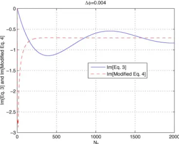
The first numerical example is related to the convergence of the summation in (3). As explained in [18], an envelope ex-traction with respect to improves the efficiency and accuracy of the summation over . Consequently, the infinite summa-tion converges by summing relatively small number (referred to as ) of cylindrical eigenmodes. This is illustrated in Fig. 3, where the imaginary part of [argument of in (3)] and its envelope extracted version [named as the modified (4)] versus is plotted for , and
for a dielectric coated PEC cylinder with ,
, at . The
modified (4) can easily be obtained from (4) by simply setting . As seen in Fig. 3, the imaginary part of mod-ified (4) converges approximately . This value is sufficient for all components though only is provided here. Note that the real part of both equations converge rapidly.
Next, input impedance of several probe-fed microstrip patch antennas and the mutual coupling between two probe-fed patches are obtained using the MoM/CFGF technique that uses
Fig. 3. Imaginary parts of (3) and modified (4) versus for for
, , , , and .
proposed CFGF representations (in the presence of the afore-mentioned attachment mode), and compared with the available results in literature as well as the results obtained from a commercial software CST Microwave Studio (its time-domain solver is used) to assess the accuracy of the proposed CFGF representations. In all numerical results, obtained via using the proposed CFGF representations, PWS basis functions are used with the attachment mode given by (36). In the course of obtaining the CFGF representations for the tangential compo-nents [i.e., for (12)], the GPOF related parameters are selected
as , , , , , ,
, , , , , ,
, , , whereas they are selected as
, , , , , ,
, , , , , ,
, , for the probe-related components [i.e., (30)].
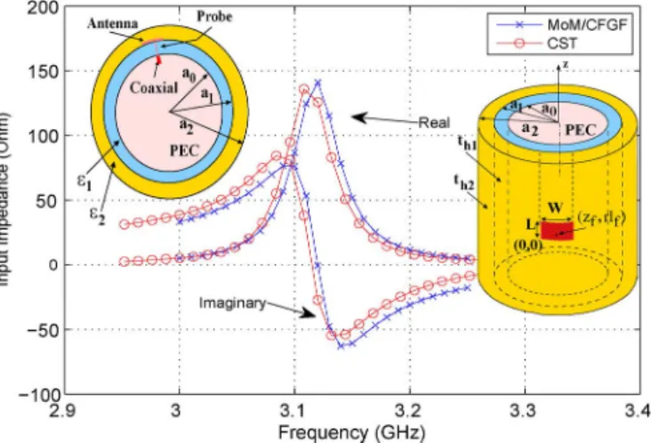
The input impedance of a probe-fed rectangular patch antenna on a dielectric coated cylinder with , , forms the first input impedance related numerical example. The dimensions of the rectangular patch are , and is excited with a mode by a probe at the feed location
, which cor-responds to the middle of its width. Fig. 4 shows the input impedance (real and imaginary parts) of this patch versus frequency where the results obtained using the MoM/CFGF technique are compared with that of CST Microwave Studio. A good agreement is obtained. In the course of obtaining the MoM/CFGF results, a total of basis functions ( , ) are used with only a -directed attachment that has the same size of a single -directed PWS basis function in the -direction and twice the size of a single -directed PWS basis function in the -direction.
The second example involves the same probe-fed antenna on the same coated cylinder (i.e., , , , , ). However, the
Fig. 4. Input impedance versus frequency for a probe-fed patch antenna with
the following parameters: , , ,
, and .
Fig. 5. Input impedance versus frequency for the probe-fed patch antenna with the same parameters as given in Fig. 4 except fed at
.
feed location is at , which is close to one of the corners. Similar to the first example, the input impedance (real and imaginary parts) versus frequency results obtained via MoM/CFGF technique are compared with that of CST Microwave Studio as shown in Fig. 5. PWS basis functions ( , ) are used together with both a -and a -directed attachment modes that have the same length with that of the - and -directed PWS modes, respectively, while their widths are twice of the corresponding PWS modes. Similar to the previous cases, a good agreement is obtained be-tween the MoM/CFGF and CST Microwave Studio results.
As the third example, the first example is revisited with the same probe location (i.e., , ,
, , , ,
) in the presence of a superstrate that has a thickness and . The input impedance versus fre-quency result, obtained using the MoM/CFGF technique, for this antenna is given in Fig. 6 together with the CST Microwave Studio result, and very good agreement is obtained. In the course
Fig. 6. Input impedance versus frequency for the probe-fed patch antenna with the same parameters as given in Fig. 4 except with a superstrate with
, .
Fig. 7. Input impedance versus frequency for the probe-fed patch antenna with the same parameters as given in Fig. 4 located on the top of two dielectric layers.
The parameters are , , ,
and .
of obtaining the MoM/CFGF results a total number of
PWS basis functions ( , ) and only the -di-rected attachment mode are used. The size of the attachment has the same size of a single -directed PWS basis function in the -direction and twice the size of a single -directed PWS basis function in the -direction.
Finally, as the last single antenna example, a similar geometry to that of the third example is considered. Briefly, a
by antenna, fed with a probe at , , is on the top of two dielectric layers which coax-ially surround the PEC cylinder with a radius of . The first layer has a thickness and , and the second layer has a thickness and . Fig. 7 shows the input impedance versus frequency results, obtained using the MoM/CFGF technique and the CST Microwave Studio. As the previous examples, very good agree-ment is obtained. A total number of PWS basis func-tions ( , ) and only a -directed attach-ment mode are used. The attachattach-ment mode has the same size
Fig. 8. Input impedance versus frequency for increasing number of basis func-tions in the presence of an attachment mode for a patch with the following
pa-rameters: , , , ,
, and .
Fig. 9. Input impedance versus frequency for increasing number of basis func-tions in the absence of an attachment mode for the same geometry given in Fig. 8.
of a single -directed PWS basis function in the -direction and twice the size of a single -directed PWS basis function in the
-direction.
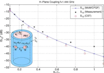
For the next set of numerical results, effect of the attach-ment mode and the mutual coupling calculations between two microstrip antennas are carried out for two identical microstrip patch antennas given in [26]. The dimensions of each patch in [26] are , , and they are mounted on a coated cylinder with the parameters , , , . Feeding the antennas with a probe at to excite the mode yields a resonance at 1.444 GHz as seen in Fig. 8, where the input impedance versus frequency results are obtained by using both the MoM/CFGF technique and CST
Fig. 10. E-plane coupling results for the geometry given in Fig. 8.
Fig. 11. H-plane coupling results for the geometry given in Fig. 8.
Microwave Studio. In the course of obtaining the MoM/CFGF results, the number of basis functions is gradually increased ( with , ; with , and finally with , ) and the convergence of MoM/CFGF technique is investigated in the presence of an attachment mode. A -directed attachment mode is used whose dimension is the same with that of the -directed PWS mode along the -direction and is twice of that of the -directed PWS mode along the -direction. On the other hand, if the input impedance versus frequency results of the same antenna is investigated in the absence of the attachment mode, a convergence problem can be observed, where the imaginary part of the input impedance becomes less accurate as the number of basis functions is increased as seen in Fig. 9.
Then, using basis functions for each antenna ( , ), the E- and H-plane coupling coefficients, given by (47), versus edge-to-edge spacing ( and , respectively, : free-space wavelength) between these patches (on the same cylinder) are presented in Fig. 10 and Fig. 11, spectively, at 1.444 GHz. For both cases, the MoM/CFGF re-sults are compared with that of CST Microwave Studio as well as the measurement results given in [26]. In all cases, very good agreement is achieved.
Finally, it should be noted that the efficiency of the presented hybrid MoM/CFGF solution strongly depends on how efficient the proposed CFGF representations are evaluated. It takes ap-proximately 2–3 seconds to evaluate each entry of the MoM impedance matrix using MATLAB on a regular personal com-puter. However, it should be mentioned that the evaluation of the CFGF representations and certain evaluations in the MoM procedure have not been optimized yet. In particular, the main bottleneck in this calculation is the two-fold (or originally four-fold) numerical integrations used to calculate the mutual impedance between two PWS current modes (i.e., basis and testing functions), and this part has to be optimized. Besides, in each numerical example presented in this paper, significantly more basis functions are used than what is required to guarantee high accuracy. Using less number of basis functions, still high accuracy can be achieved. On the other hand, to generate the CST Microwave Studio results, remarkably powerful workstations with multi cores and RAM values in the order of 10 GB are used. However, the required CPU time for one frequency point during the input impedance calculations or one distance point during the mutual coupling coefficient calculations significantly favors the hybrid MoM/CFGF technique presented in this paper.
V. CONCLUSION
New CFGF representations for cylindrically stratified media, which constitute the kernel of an EFIE, are developed and used in conjunction with a Galerkin MoM solution procedure, re-ferred to as the hybrid MoM/CFGF technique, to investigate probe-fed microstrip antennas on multilayered circular cylin-ders. An attachment mode is used to model the feeding accu-rately by ensuring the continuity of the current from probe to the patch. Very accurate results are obtained both in terms of the input impedance of single antennas and mutual coupling be-tween two antennas.
The accuracy and efficiency of the proposed hybrid MoM/ CFGF technique strongly depend on the computation of the CFGF representations, which are used everywhere including the source region as well as for the probe-related components (in-cluding the attachment mode). Therefore, all singularities that appear in the source region in addition to the axial line are an-alytically treated. Furthermore, because of several techniques used in the course of derivations, printed structures can be inves-tigated both for electrically small and large cylinders. However, it should be kept in mind that the approximating functions, that are used to evaluate the CFGF representations, represent spher-ical waves with complex distances. Thus, types of waves that are different in nature than spherical waves, such as surface waves, are not represented properly and their effects are not included in this study as oppose to some studies for planar geometries. Thus, the CFGF representations proposed in this paper are less accurate for large separations, where surface waves dominate.
REFERENCES
[1] Y. L. Chow, J. J. Yang, D. F. Fang, and G. E. Howard, “A closed-form spatial Green’s function for the thick microstrip substrate,” IEEE Trans.
Microw. Theory Tech., vol. 39, no. 3, pp. 588–592, Mar. 1991.
[2] G. Dural and M. I. Aksun, “Closed-form Green’s functions for general sources and stratified media,” IEEE Trans. Microw. Theory Tech., vol. 43, no. 7, pp. 1545–1552, Jul. 1995.
[3] M. I. Aksun, “A robust approach for the derivation of closed-form Green’s functions,” IEEE Trans. Microw. Theory Tech., vol. 44, no. 5, pp. 651–658, May 1996.
[4] S. Raffaelli, Z. Sipus, and P.-S. Kildal, “Analysis and measurements of conformal patch array antennas on multilayer circular cylinder,” IEEE
Trans. Antennas Propag., vol. 53, no. 3, pp. 1105–1113, Mar. 2005.
[5] K.-L. Wong, Design of Nonplanar Microstrip Antennas and
Transmis-sion Lines. Hoboken, NJ, USA: Wiley, 1999.
[6] L. Josefsson and P. Persson, Conformal Array Antenna Theory and
Design. Hoboken, NJ, USA: Wiley, 2006.
[7] A. Y. Svezhentsev and G. A. E. Vandenbosch, “Spatial Green’s function singularity for sheet electric current over dielectric coated cylinder,” IEEE Trans. Antennas Propag., vol. 52, no. 2, pp. 608–610, Feb. 2004.
[8] A. Y. Svezhentsev and G. A. E. Vandenbosch, “Efficient spatial do-main moment method solution of cylindrical rectangular microstrip antennas,” IEE Proc.-Microw Antennas Propag., vol. 153, no. 4, pp. 376–384, Aug. 2006.
[9] T. Bertuch, F. Vipiana, and G. Vecchi, “Efficient analysis of printed structures of arbitrary shape on coated cylinders via spatial-domain mixed-potential Green’s function,” IEEE Trans. Antennas Propag., vol. 60, no. 3, pp. 1425–1439, Mar. 2012.
[10] Y. Hua and T. K. Sarkar, “Generalized pencil-of-function method for extracting poles of an EM system from its transient response,” IEEE
Trans. Antennas Propag., vol. 37, no. 2, pp. 229–234, Feb. 1989.
[11] V. I. Okhmatovski and A. C. Cangellaris, “Evaluation of layered media Green’s functions via rational function fitting,” IEEE Microw. Wireless
Compon. Lett., vol. 14, pp. 22–24, Jan. 2004.
[12] L.-F. Ye, F. Zhao, K. Xiao, and S.-L. Chai, “A robust method for the computation of Green’s functions in cylindrically stratified media,”
IEEE Trans. Antennas Propag., vol. 60, no. 6, pp. 3046–3051, Jun.
2012.
[13] C. Toköz, “Derivation of closed-form Green’s functions for cylindri-cally stratified media,” M.S. thesis, Dept. Elect. Electron. Eng., Middle East Technical Univ., Ankara, Turkey, Aug. 1997.
[14] C. Tokgöz and G. Dural, “Closed-form Green’s functions for cylindri-cally stratified media,” IEEE Trans. Microw. Theory Tech., vol. 48, no. 1, pp. 40–49, Jan. 2000.
[15] J. Sun, C.-F. Wang, L.-W. Li, and M.-S. Leong, “A complete set of spatial-domain dyadic Green’s function components for cylindrically stratified media in fast computational form,” J. Electromagn. Waves
Appl., vol. 16, no. 11, pp. 1491–1509, 2002.
[16] J. Sun, C.-F. Wang, L.-W. Li, and M.-S. Leong, “Further improvement for fast computation of mixed potential Green’s functions for cylindri-cally stratified media,” IEEE Trans. Antennas Propag., vol. 52, no. 11, pp. 3026–3036, Nov. 2004.
[17] J. Sun, “Development of Green’s functions and its application for cylin-drically stratified media,” Ph.D. dissertation, Dept. Electr. Comput. Eng., Nat. Univ. Singapore, Singapore, 2004.
[18] S. Karan, V. B. Ertürk, and A. Altintas, “Closed-form Green’s func-tion representafunc-tions in cylindrically stratified media for method of mo-ments applications,” IEEE Trans. Antennas Propag., vol. 57, no. 4, pp. 1158–1168, Apr. 2009.
[19] J. Wu, S. K. Khamas, and G. G. Cook, “An efficient asymptotic ex-traction approach for the Green’s functions of conformal antennas in multilayered cylindrical media,” IEEE Trans. Antennas Propag., vol. 58, no. 11, pp. 3737–3742, Nov. 2010.
[20] L.-F. Ye, S.-L. Chai, H.-S. Zhang, D. Peng, and K. Xiao, “Solving the axial line problem for fast computation of mixed potential Green’s functions for cylindrically stratified media,” IEEE Trans. Antennas
Propag., vol. 61, no. 1, pp. 23–37, Jan. 2013.
[21] J. Wu, S. K. Khamas, and G. G. Cook, “Moment method analysis of a conformal curl antenna printed within layered dielectric cylindrical media,” IEEE Trans. Antennas Propag., vol. 61, no. 7, pp. 3912–3917, Jul. 2013.
[22] N. Kinayman and M. I. Aksun, “Efficient use of closed-form Green’s functions for the analysis of planar geometries with vertical connec-tions,” IEEE Trans. Microw. Theory Tech., vol. 45, no. 5, pp. 593–603, May 1997.
[23] T. Onal, “Development of rigorous and efficient electromagnetic simu-lation algorithm for 3-D printed structures in multilayer environment,” M.S. thesis, Dept. Electr. Comput. Eng., Koc Univ., Istanbul, Turkey, 2005.
[24] S. Karan, “Method of moments analysis of microstrip antennas in cylin-drically stratified media using closed-form Green’s functions,” Ph.D. dissertation, Dept. Electrical Electron. Eng., Bilkent Univ., Ankara, Turkey, 2012.
[25] M. Marin and P. H. Pathak, Calculation of the surface fields created by a current distribution on a coated circular cylinder Dept. Electr. Eng. Columbus, OH, USA, Tech. Rep. 721565-1, Apr. 1989, 43212, Grant No. N00014-89-J-1007.
[26] C. Y. Huang and Y. T. Chang, “Curvature effects on the mutual cou-pling of cylindrical-rectangular microstrip antennas,” Electron. Lett., vol. 33, pp. 1108–1109, 1997.
Sakir Karan received the B.S., M.S., and Ph.D.
de-grees from the Electrical and Electronics Engineering Department, Bilkent University, Ankara, Turkey, in 2003, 2006, and 2012, respectively.
He has been working for Aselsan Electronics Incorporated, Ankara, Turkey, as an RF Design Engineer since 2003. His research interests include application of numerical methods to radiation and mutual coupling problems associated with cylin-drical structures.
Vakur B. Ertürk (M’00) received the B.S. degree
in electrical engineering from the Middle East Tech-nical University, Ankara, Turkey, in 1993, and the M.S. and Ph.D. degrees from The Ohio-State Univer-sity (OSU), Columbus, OH, USA, in 1996 and 2000, respectively.
He is currently with the Electrical and Elec-tronics Engineering Department, Bilkent University, Ankara. His research interests include the analysis and design of planar and conformal arrays, high-fre-quency techniques, structural health monitoring, magnetic resonance imaging, scattering from and propagation over large terrain profiles.
Dr. Ertürk served as the Secretary/Treasurer of IEEE Turkey Section as well as the Turkey Chapter of the IEEE ANTENNAS ANDPROPAGATION, Microwave Theory and Techniques, Electron Devices and Electromagnetic Compatibility Societies. He was the recipient of 2005 URSI Young Scientist and 2007 Turkish Academy of Sciences Distinguished Young Scientist Awards.