Variations in design process:
A case study about tool and
task as design variants
Abstract
Several researchers question the nature of design. Although design has specific characteristics that distinguish it from other cognitive activities, it also takes on different forms depending on the main factors of the design setting.
To test this idea, this study has adopted design tools and tasks as the factors that change a design situation. In order to do that, a case study with one graduate student enrolled in Design Computing Program at Istanbul Technical University, Istanbul is conducted. The case is composed of four design sessions, each consist-ing of a unique combination of a tool and task.
The analysis of the protocol aims to show how the different phases of a design process come together in different weights when working on the task depending on the problem given and the tool adopted.
This study can be framed as adopting an activity based model where the actions of the participant are in a problem-oriented setting that requires re-production before re-iteration and are assessed through an analytical approach of coding ac-tivity in order to understand the impact of the design tool as a variant of the process.
The results suggest that tools have a diverging effect on the process as they require different operational methods. On the other hand, the nature of design tasks converge designer’s thoughts into a predictable pattern. The combination of the divergence and the convergence yields a spectrum of unique design situations.
Keywords
Design tool, Design process, Design variant, Tool cognition.
Betül ORBEY1, Sinan Mert ŞENER2
1 [email protected] • Department of Architecture, Faculty of Fine Arts and
Design, Doğuş University, Istanbul, Turkey
2 [email protected] • Department of Architecture, Faculty of
Architecture, Istanbul Technical University, Istanbul, Turkey
Received: May 2016 •Final Acceptance: November 2016
do
i: 10.5505/i
tu
1. Introduction
This study is conducted as part of a Ph.D thesis inspired by Visser’s work on augmented generic design, and ar-gues that tools adopted act as design variants affecting the design process. In addition, Fish (2004) claims that a mental tree of design possibilities ex-ists in designer’s mind; and this study claims that the adopted design tools are variants that effect the paths that the designer follows among the branches of this tree. Fish also argues that each path requires the designer to practice a certain set of cognitive acts in shaping the design process which, this study aims to quantify through the use of de-sign tools.
However, a design situation can not be reduced to an isolated setting con-sisting of merely one variable being tested. Thoughts of a designer are as much related to the type of design task given as it is to design tool adopted. Therefore, this study comparatively an-alyzes tools against two types of design tasks. This allowed for a better under-standing of dependencies between de-sign variants that can be defined by tri-angle of the actor target and tool (von Leeuwen, Smitsman, & von Leeuwen, 1994) in the most basic approach.
The case study has aknowledged for a deeper understanding of the interde-pendent relation not only between the designer and the tool, but also between the type of design problem and the tool studied through a lens investigat-ing the design process in a variety of design settings. It has attempted to in-carnate Visser’s approach with tangible examples and data that reveal the inner workings of the design process. These examples and data indicate cognitive differences due to the adopted design tools and the type of the design task given.
The case study involved one volun-tary graduate student enrolled in the Architectural Design Computing Pro-gram at Istanbul Technical University. The case is composed of four design sessions, each consisting of a unique combination of one of the two types of problems to be tackled using physical modelling and one of the two distinct physical modelling tools utilized for the shared act of cutting.
The case is analyzed in three ways. The first set of analysis considers the tools as means of production by com-paring them in a non-design task in terms of mental representations; and the second considers the tools as means of design by comparing tools in a design task. Third reading studies the design process altered by the ad-opted tools for the given tasks through phases of design activated in each tool and task combination.
This article deals with the third read-ing that tries to understand the interac-tions between design variants in hand, the design tool and the design problem, at the scale of design phases in order to give a general sense of the impact that the tool and the task makes on the pro-cess. It attemts to quantify how the dif-ferent phases of a design proccess come together in different weights to accom-plish the task depending on the design problem given and the adopted tool.
2. Theoretical background
Visser (2009) poses that although “design has specific characteristics that distinguish it from other cognitive ac-tivities, it also takes on different forms depending on the main dimensions of the design situation” (p. 2). Conse-quently, she confirms that “there are both significant similarities between the design activities carried out in dif-ferent situations” (Visser, 2006) and important distinctness between design and other cognitive activities as put forward in the generic design hypothe-sis (Goel, 1995; Gero & Purcell 1998).
Visser introduces a new position to augment the generic design notion by proposing that characteristics of a de-sign situation introduce specifities in the corresponding cognitive activities and structures that are used in the re-sulting design (Visser, 2009). She de-fines three dimensions as source for difference in design: the process, the
designer and the artefact with relevant
subsets to each. The focus of this study, design tools, are categorized under process with an emphasis on cognition.
2.1. Tool cognition
Technologies are advanced and ex-panded so that we can do things that are not possible to achieve without the
help from technological advances, or so that they are inexpensive, speedy, and simple (Volti, 1992). Left with only the inherent physical capabilities, humans cannot reach certain capaci-ties such as speed, strength etc. Over-all, humankind is physically weak but it compensates for this physical weak-ness through intelligence which in re-turn makes technology possible. (Volti, 1992)
Simondon (2012) distinguishes be-tween a technical object and a tool by defining that technical objects are always embedded within larger net-works of technical assemblies, includ-ing geographic, social, technological, political, and economic influences. On the contrary, like Hayles, I find it diffi-cult to find a tool, as simple as it may be, that does not suit this definition. Accordingly, I depart from Simondon and find parallels with Hayles (2012) by considering tools as part of tech-niques and their potential in allowing for exponential change.
At the root of the word technolo-gy is the ancient Greek word tekhne, which is translated as “art,” “craft”, or “skill” (Volti, 1992) which we associate with craftsmanship; and “logos”, which refers to a framework of principles de-rived from the cognitive act of reason-ing. “Tekhne” and “logos” were used together in classical literature to reveal the art of reason, or the skill involved in making. And this study values un-derstanding the reasoning behind tools and technology that are in fact so pow-erful that change our own reasoning.
However important it may seem, bibliometric studies indicate that role of tool in cognition is an under studied field compared to its language counter-part. In 1998, Preston has noted 15736 entries under the subject heading ‘language’, 28 entries under “tool” and another 94 under “artifact” (Preston, 1998). On the other hand, Andy Clark (2003) suggests that “what makes us distinctively human is our capacity to continually restructure and rebuild our own mental circuitry, courtesy of an empowering web of culture, education, technology, and artifacts” (Smedes, 2005). With his quote, he frames why tools are worth studying contrary to what bibliometric data might suggest.
Our brains re-structure and re-build our mental circuitry so seamlessly that the tools or technologies become transparent, meaning that they become very well integrated. Smedes (2005) ex-emplifies this through sticks becoming an extension of the touch sense, in the case of the blind person; or cars ex-tending our bodily motor capacities; or pens and pencils becoming extensions of our hands, and the paper becoming an extension of our cognitive device: by writing something down, we do not need to remember it any more as it is now externally stored on a piece of pa-per. In short, by technology and tools, we both manipulate human nature, and we also push ourselves beyond our physical and mental capabilities. (Sme-des, 2005)
When technologies are used ubiq-uitously surrounding and defining our environment, they do more than just allowing for the external storage and transfer of thoughts. According to Clark (2003), they constitute “a cascade of mind ware upgrades”. Many of our tools are not just external aids, but they are “mind ware upgrades” that are also deep and integral parts that re-define our problem-solving systems. There-fore, design tools are taken as variants that shape the design process; and this study focuses on the impact of a design tool on design process. Variety of defi-nitions and approaches to models of design processes is explored next.
2.2. Design process models
According to Broadbent and Ward (1969) Jones defines six design meth-ods and the most important three of them are: “black box”, “glass box”, problem structure. The “black box” method reveals a mysterious approach to design and claims that design pro-cess can not be analyzed because is an abstract process that takes place in the designer’s mind. The “glass box” method takes design as a sequencce of happenings that consists of identi-fication, analysis, synthesis and evalu-ation (Broadbent, 1969). In the “prob-lem structure” method, consisting of many iterations, Asimow (Asimow, 1962) makes a diagram of preliminary design and shows the steps to identify the best design approach from a
num-ber of other alternatives. A latter view by Rittel and Webber (1973) suggests that design process can not completely be described thus, it is not susceptible to a complete analysis (Cross, 1975). Royal Institute of British Architects (RIBA) on the other hand, lists a lineer structure of design process consisting of eight phases starting with identi-fying requirements and ending with post-construction feedback (RIBA, 2016).
Many definitions of the design pro-cess either elaborate the propro-cess at a macro level or reveal the order of com-prehended results and not how the de-signer behaves (Gericke and Blessing, 2011). Most of the process models sug-gest a market driven process (market pull) contrary to technology driven processes (technology push) (Gericke & Blessing, 2011). Opposingly, Maffin (1998) suggests that new models of the design process should be informed by interpretation of context istead of prescribing the ideal process. Accord-ing to Design Council’s (2007) report, “Our world is evolving so quickly that there may never be an ideal methodol-ogy or process”. Although there is no universel design process applicable in every design context, they agree with Eckert and Clarkson (2005) and Best (2006) that common generic stages exist, independent of domain and that this core needs adaptation to context (Gericke and Blessing, 2011).
In order to analyze design processes shaped by the context which is a tool variant in this case, this study asks whether it is possible to compare tool related differences between design processes in the case of design problem situations; non-design problem situa-tions and accross design and non-de-sign problem situations, according to the framework put together by Wynn and Clarkson (2005).
Wynn and Clarkson (2005) define three schemes that have interrelated dimensions: stage based model vs. ac-tivity based model; problem oriented vs. solution oriented approach; abstract approaches vs procedural approaches vs. analytical approaches.
According to this framework, stage based models structure the design process according to its design phases
and activity based models represent the design process through activities conducted during the course of design (Blessing, 1996). A typical characteris-tic of an activity is that it reappears for a number of times during the design process.
Solution-oriented models propose a solution, analyse it and repeatedly modify it to explore the design space. On the other hand, problem oriented models put emphasis on analysis and understanding of the design problem before generating a range of design al-ternatives (Wynn and Clarkson, 2005).
Abstract approaches tend to de-scribe the design process at a high level of abstraction which corresponds to a broad range of situations (Wynn and Clarkson, 2005). Procedural approach-es on the other hand, are more con-crete and they focus on certain aspects of design projects relating to practical situations. Analytical approaches are used to better understand the design process through the use of techniques, procedures or computer tools (Brown-ing, 2001).
This study adopts an activity based model where the actions of the partic-ipant in the case study is noted and as-sessed in terms of repeating chunks in a problem-oriented setting where, the first phase of the case requires re-pro-duction of the given problem geometry and the second phase requires a design activity through re-iterations to gener-ate a range of possible solutions; and the results are assessed through an
an-alytical approach through an approach
that encodes activity in order to un-derstand the impact of design tool as a variant of the process.
3. Method
Activity Theory is a qualitative re-search method that helps finding pat-terns and making meaning across actions. An activity is a goal oriented interactive stage where the actor in-teracts with an object through the use of a tool. “These tools are exteriorized forms of mental processes manifested in constructs, whether physical or psy-chological. Activity Theory recognizes the internalization and externalization of cognitive processes involved in the use of tools, as well as the
transforma-tion or development that results from the interaction” (Fjeld, et al., 2002).
This study finds parallels with the theoretical background of Activity Theory developed by Nardi and Kuutti (1993) and adopts a similar approach focusing on the activities taking place during design sessions and their in-terdependent relation with eachoth-er. Each four design session is video taped, the recordings are divided into five minutes intervals and each interval is analyzed using the acts performed by the participant. Each act conducted by the participant is noted, composing a sequence of activity. This data pro-vides insight about the design process according to patterns that emerge from identification of repeating action cou-ples, which are defined as chunks of action that appear in the same order for multiple times during the design process.
This study re-interprets Suwa and colleagues’ (Suwa, Gero, & Purcell, 1998) content oriented approach to protocol analysis and coding scheme to provide data that yields a process oriented understanding of the design phases in the end.
3.1. Coding scheme
Video recordings taken during de-sign processes are analysed and each move the participant made is not-ed. The activities recorded are then grouped into three action categories.
Meanings are drawn from the frequen-cies of these action categories, and pat-terns emerging from repeatedly cou-pling actions, forecasting indicators regarding the nature of the process. Activites, action categories and con-cepts that emerged are detailed in the following sections.
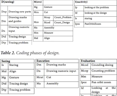
The participant’s activities are grouped into three groups: Drawing, Move, Inactivity. These categories emerged from observations and gen-eralization of various actions during the process. Inactivity category refers to the state of being motionless and the categories of Drawing and Move refer to state of motion. Action categories related to each activity are listed and assigned a code as abbreviation (Table 1).
Concepts on the other hand, are in-terpretations of data regarding actions and activities and reveal insight about the design process. These concepts have emerged through repetition of action chunks that reveal meaningul intentions/decision and dependency analysis where the intentions behind actions are sought for by looking at proceeding and preceeding actions for each move (Table 2).
4. The study
The study is pursued in two phases: In the first phase the aim is to under-stand the effect of a design tool during the process of physically building a geometry that have been given to the participant (non-design situation). In the second phase the aim is to under-stand the impact of the same design tool during the process of re-interpret-ing the geometry in a creative fash-ion (design situatfash-ion). The first phase therefore, investigates the design tool as means of production and the sec-ond phase investigates the same tool as means of design.
The time allowed for re-produc-tion of the image is 15 minutes during the first phase and during the second phase of the experiment,the partic-ipant is asked to produce at least two iterations of her understanding of the initial geometry with a time limit of 15 minutes for each iteration. Sketching is allowed during all phases of the exper-iment. The whole proccess is
conduct-Table 1. Coding actions of Drawing, Move and Inactivity.
ed with two design tools chosen to be compared.
4.1. Tools
Comparison criteria selected are production method, operator and modeling method. Production method criteria refers to the type of production process such as additive, subtractive, cut or formative which are abbreviat-ed as Ad, S, Cu and F respectively. Ad-ditive method proceeds with adding layers/parts of the model proposed. Subtractive method proceeds with the removal of the parts of the whole that are not needed for the model. And for-mative method proceeds with model-ling of the negative space around the positive that needs to be modelled, which is then filled with a porous ma-terial to form the positive parts.
A distinction is made on who is op-erating the process. The reason for this assessment is the belief that although human factor is involved in design-ing the pre-production phase in either case, running a process manually (M) or digitally (D) involves or excludes technology and alters the procedural steps needed to operate the tool. Thus, it alters the method of production and the way a designer thinks.
Modelling method is also taken as a criterion since it is possible to think computationally (Co) through a man-ual process or analogous (An) in a dig-ital medium.
According to this, laser cutter and x-acto knife pair is selected for fur-ther study. The reason behind it is that these two tools show similarities both in modelling and production method and only differ in by whom they are operated. They both pursue the act of cutting through analogue methods but the designer has to mark where to cut either manually or digitally; the path is not generated computationally as it would be in three dimensional model-ling software.
4.2. Tasks
Two distinct geometries were de-signed for the experiment on a 3D modelling software. The relations of the parts were designed by the author so that the participant is not allowed to design during the first task
(non-de-sign), where the task is solely to repli-cate the image as a physical model to test the tools as means of production.
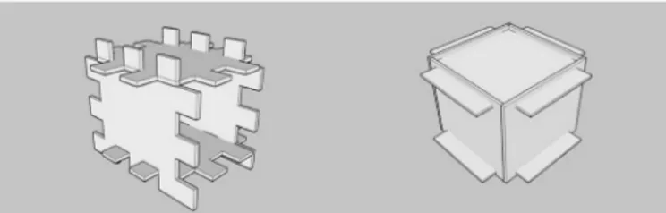
Tasks consisted of two different ge-ometries named G1 and G2 and they are addressed with both of the design tools in total of 4 experimental set-tings. Each geometry is assigned a de-sign tool to be utilized both in a dede-sign task and a non-design task. The geom-etry named G1 is based on a rectan-gular prism and G2 is based on a cube (Figure 1). It has been useful in avoid-ing a serial position, which refers to the experience gained during the first phase and may be carried out onto the second phase, by allowing a fresh start with the new design tool.
5. Results
5.1. X-acto knife use in design
This design process consists of 74% of Moves, 11% of Drawing and 14% of
Inactivity. At this scale, it is clear that
the moves are the driving force behind the design decisions. This should show us that process of physical model mak-ing is independent of sketchmak-ing and proceeds with variety of Moves. The array of moves recorded in this process are as follows: Malign, Mcut, Massem-ble, Mmeasure and Mgesture.
Acts of Drawing and Inactivity pro-vide either visual aid to the design-er or an opportunity to re-intdesign-erpret, evaluate or further evolve the model. Acts of Inactivity recorded are I_look-ing_at_design and Ipan_orbit_zoom, where I_looking_at_design provides an opportunity to review the design proposal and a basis for re-interpreta-tion and Ipan_orbit_zoom allows the designer to view the model from dif-ferent angles.
The only act of drawing that is re-corded and that makes up the 14% of the actions is Dmarks. Dmarks are uti-lized to make a record of the decision made rather than to produce ideas in
the form of a sketch.
Moves are interrupted by Draw-ing activity especially by Dmarks ac-tion for the first ¾ of the process and interrupted by Inactivity for the last quarter. This means that the first ¾ of the process consists of making design decisions and elaborating the design proposal by seeking guidence from the Marks made and the last quarter of the process consists of evaluating the pro-posal through inactive states of looking at the design proposal.
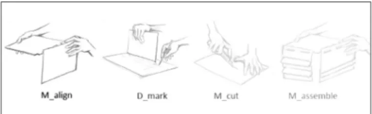
Notable patterns of action are Ma-lign + Dmarks; MaMa-lign+Dmarks+M- Malign+Dmarks+M-cut; Malign+Dmarks+Mcut+Massem-bly (Figure 2). These patterns indicate that the designer reflects on what she sees –that is what she builds- therefore a move that aligns two parts is fre-quently followed by marking the posi-tion which is then cut and assembled in the end. The smallest chunk of this
pattern is to align+mark. The design-er may chose not to continue to othdesign-er parts of the chain and revise her deci-sions according to what she sees emerg-ing. Or she may evaluate the proposal as she builds and sees it to complete the whole pattern of align+mark+cut+-assemble. Therefore, this part of the experiment is said to present compli-ance with Schön’s (1983) reflection in action process.
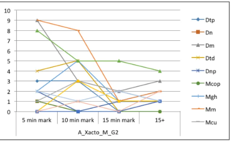
During the first five minutes, Ma-lign, Dmark, Mcut and Massembly acts take place (Figure 3). Most prominent of those is the Malign + Dmark action chunk. These two acts initiate the deci-sion making phase of the process. The designer visualizes the outcome of his proposal through simulation provid-ed by the act of aligning. She manip-ulates it and ends the decision process through marking.
During the next five minutes, un-til the 10 minute mark, Malign drops yielding the executive act of Mcut ac-company the external marks of design decisions (Dmark) so that the see-move-see cycle (Goldschmidt, 1991) can be completed through Mcut+Mas-semble action chunk to review the out-come (Figure 4).
In this part of the timeline, Mgesture starts to appear for the first time. 85 % of the time, Mgesture is followed by Mcut. Mgesture+Mcut action chunk reveals that Mgesture acts as a visu-al aid supporting seeing that yields a design decision followed by a design move, executing the decision (Figure 5).
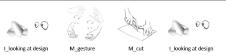
During the next five minutes, un-til the 15 minute mark, Mcut makes a peak. The reason for this may be that a single act of cutting is not enough to complete the execution of a design move, therefore the act itself is re-peated multiple times. The chunks of moves analyzed show that design de-cision process is still on, but through a slightly different sequence. Ilook-ing_at_design+Mgesture +Mcut+I-looking_at_design action chunk in this part appears frequently to make up the see-move-see cycle (Goldschmidt, 1991) (Figure 6). The designer looks at the design to evaluate the proposal, makes a gestural move to simulate the design move in her mind in order to
Figure 4. Action chunk 3 during x-acto
knife use in design task.
Figure 3. Action chunk 2 during x-acto
knife use in design task.
Figure 2. Action chunk 1 during x-acto knife use in design task.
Figure 5. Action chunk 4 during x-acto knife
see, and executes the decision through Mcut followed by another actor eval-uation with Ilooking_at_design. Ab-sence of Dmarks does not point to an absence in design decisions. It shows that Dmarks act as an external way of storing the information embedded in the decision. This is why we observe Mcut right after Mgesture and nothing else in between. Means of execution available here eliminates the need to externally represent design decisions.
During the part that is post 15 min-utes, the rate of Mcut drops and acts of evaluation such as I_looking_at_ design or Ipan_orbit_zoom appear. The designer makes her last decisions through gestures and executes them through new cuts followed by pauses to look at the design and orbit the model so that it is viewed from different an-gels (Table 3).
The seeing phase of the design cess makes its peak as the design pro-cess initiates but falls in a decreasing trend throughout the overall process. Execution phase of design starts at a relatively lower rate, but draws an in-creasing trend untill the end of 15 min-ute mark (Table 4). Evaluation phase presents an increasing trend for the first 15 minutes and a constant rate for the rest of the time remaining. These trends provide us with insight regard-ing the nature of the process. The de-sign task when x-acto knife is utilized utilizes doing rather than visualizing, because the design itself is an emerg-ing prototype as the designer acts on it. Therefore, evaluation phase supresses seeing, and the ease of acting on the tangible physical model puts emphasis on the execution phase. Thus, this pro-cess can be characterized with doing and reacting.
5.2. X-acto knife use in non-design
This session consists of 33% Draw-ing acts, 37% MovDraw-ing acts and 29% Inactivity. The balance in the use of specified activities present a wide spec-trum of actions related. Drawing acts recorded during this session consists of Dtracing_problem, Dnumeric_in-put, Dmarks_guides, Dtracing_design, Dnew_parts. Moving acts recorded in this session consists of Mcounting_ problem, Mgesture, Mmeasure, Mcut
and Mcounting_design. And Inactivity in this session consists of I_looking_ at_the problem, Ilooking_at_the_de-sign and Istaring.
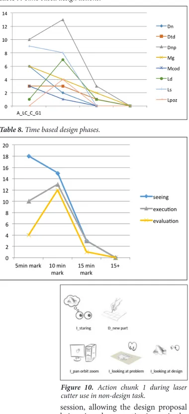
During the first five minutes of the session, the designer makes acts of intense measurements and marking along with acts of looking at the prob-lem in order to understand the geome-try. Here, the action chunk Mmeasure + Dmarks is recorded frequently. The designer starts the session with inves-tigating the problem geometry, mark numeric input on the given geometry and then a long sequence of Mmea-sure+Dmarks starts.
The other acts recorded in this part of the session and are worth
mention-Figure 6. Action chunk 6 during x-acto knife use in design task. Table 3. Time based design actions.
ing are Dtracing_problem and Dtrac-ing_design (Figure 7). These acts are carried out to either understand the geometry or the part that is planned to be cut.
During the second five minutes, the act of Mmeasure continues at the same rate along with the act of Ilook-ing_at_the_problem in order to make sure parts designed will make up the geometry given when constructed. Dtracing_design here also helps the designer to specify the contours of the parts to be cut.
Gestural acts of Mgesture are re-corded at its peak in this session when the designer is in the stage of designat-ing the parts to be cut through Dtrac-ing_design and the act of Mgesture is hypothesized to help the designer vi-sualize how the part will fit with the other parts once it’s constructed in 3D. Therefore the action chunk I_looking_ at_the_problem+Mgesture appears frequently as the result of the design-er’s intention to simulate the results of
his action, to make sure it replicates the problem given (Figure 8). And the act of cutting is more frequently recorded during this part. This means that the designer has taken design decisions and is in the phase of executing them.
During the next five minutes, the ac-tivity of the designer drops but the rate at which Ilooking_at_the_problem stays constant for the designer con-stantly checks if the parts drawn are in accordance with the problem geometry given. In addition to Ilooking_at_the_ problem the designer, makes Dmarks and moves of Mcut and evaluates her design through Ilooking_at_the_de-sign.
During the last five minutes, the rate of Ilooking at the problem stays con-stant but she records many other acts at dipensable times. The reason for this messy character of activity is that she realizes that her model is not suf-ficient to replicate the geometry given when constructed in 3 dimension and that she looks for ways to understand the reason why such an inconsistency has happened. Therefore, she makes random acts once or twice each to see if she can sort the problem through them. Finally, the allotted time ends during her search for a solution before the model is complete. (Table 5)
This design process shows a de-creasing level of activity overall, and an ondulating phase of seeing that starts with an increase in the first ten min-utes, then drops dramatically for the next five minutes and increases again for another five minutes. In this pro-cess, the activity level of the evaluation phase is always the highest, although it shows a decreasing trend as well. Similarly, although execution starts at mid-levels, it shows a decrease during the design process and stays constant after the middle of the process (Table 6). The nature of the task given has forced the designer to force her visual-ization skills and evaluate it to execute the correct solution. However, she has failed to do so because the requirement of both visualization and execution with the task combined with manu-al operation required by the tool had a negative influence on the cognitive process of the designer. She has failed in visualizing and making sure what
Figure 7. Action chunk 1 during x-acto knife
use in non-design task.
Figure 8. Action chunk 2 during x-acto
knife use in non-design task.
she visualizes complies with the given geometry, thus the execution phase has failed as well, requiring a constant need to evaluate the problem geometry to figure out a strategy to construct it. This design process can be character-ized to put emphasis on evaluation.
5.3. Laser cutter use in design task
This session consists of 47% of draw-ing acts, 34% of inactivity and 18% of moves. This distribution of activity suggests that the designer has experi-enced a design session driven by draw-ing which is supported by phases of evaluation through inactivity. Drawing activity consist of Dnew parts, Dnu-meric_input and Dtracing_design ac-tions; inactivity is observed through Ipan_orbit_zoom and Istaring and moves that are recorded are Mgesture and Mcounting_design.
Often recorded action chunks during this session have been Mges-ture+Istaring, Istaring+Dnew parts and Mgesture+Dnew parts (Figure 9). All the three couples signify the pres-ence of an image in mind, and that it is transformed and kept alive through Mgesture + Istaring. Istaring+Dnew parts couple indicates that the decision made in the internal representation is stored as an external representation. And finally the occurance of Mges-ture+Dnew parts suggests that gestures are representations of acts taken on the internal image and the concluding form is stored in the sketches.
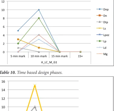
During the first five minutes of the session, an intense dialogue between Dnew_parts and Istaring starts. Dnu-meric_input and Mgesture support this couple. The designer is hypothe-sized to create an image of her design in her mind’s eye when she pauses more then 3 seconds and then makes a sketch on paper to externalize the image created. The precise nature of the design tool forces the designer to think in exact numbers, make a record of those values and think of new parts of the design according to those values. And finally in this session Mgesture is hypothesized to be a resemblance of the model created as an internal repre-sentation. Dtracing design is also ob-served as an act that helps the designer to image her design in her mind’s eye
to make sure that all the pieces will fit once they are constructed. The acts that are recorded so far suggest that the first five minutes of the session has been about constructing the design propos-al through creation of an image in the mind and transferring it on paper aid-ed by the acts of tracing and shaping the model with gestures.
In the second five minutes, in addi-tion to Dnew parts and Istaring, the de-signer also starts evaluating the design proposal through Ilooking at the de-sign. Moves of gesture keep supporting the act of creation along with the eval-uative act of Ipan_orbit_zoom in order to review the design proposal achieved so far. Dtracing design remains occur-ing at the same rate in this part of the
Figure 9. Action chunk 1 during laser cutter
use in design task.
session, allowing the design proposal being viewed as an active image in the mind. All these actions noted suggest that this phase concentrates on synthe-sis as well as evaluation.
The last five minutes of the session presents a dramatic drop in activi-ty. The actions that are still in process during this part are Dnew parts, Mges-ture, Ilooking at the design and Dtrac-ing design. It suggests that there still is an active image of the design in the
mind that is being transfered on com-puter through the help of Dtracing de-sign and Mgesture to keep the internal image alive. And the single instance of Ilooking at the design suggests that act of evaluation is still involved in the process (Table 7).
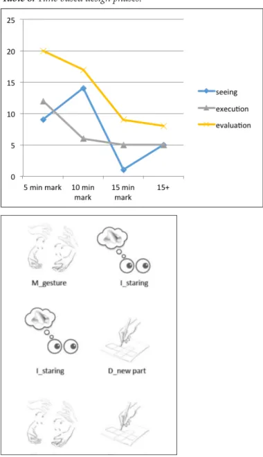
This design process stars on em-phasis on seeing and mid levels of ex-ecution accompanied by minor acts of evaluation. The rates of appearance gets closer towards the 10 minute mark; and they all decline almost con-vergingly towards the 15 minune mark. This design situation creates a process where seeing feeds execution and eval-uation accompanies them lineerly (Ta-ble 8).
5.4. Laser cutter use in non-design task
This design process consists of 48% of looking acts. These acts consists of staring, looking at the problem, look-ing at the design and pan, orbit or zoom. 76% of these acts are recorded during the second five minutes of the design process. Drawing acts on the other hand take up the 40% of the de-sign activity, of which 55% takes place in the second five minutes of the pro-cess. These numbers show that an in-crease in the rate of activity takes place during the second half of the design process.
Frequently noted action chunks in this session are Istaring+Dnew_part and Ipan_orbit_zoom+Ilooking_at_ problem+ Ilooking_at_design (Figure 10). These chunks suggest that the designer constructs a replica of the problem geometry given in her mind, transfers it on the computer screen for execution and then tries to match her input with the geometry given to make sure that they comply.
The first five minutes of the design process presents us with only 30% of the total activity. Among this, there is the 75% of Istaring signalling us that during the first five minutes the de-signer has tried to construct the pro-posal in his mind through attempts to image it internally. Chunks of Istar-ing+Dnew_part converge to the same point that the designer tries to see in his mind, draws on paper and repeats this chunk for several times during the
Figure 10. Action chunk 1 during laser
cutter use in non-design task.
Table 7. Time based design actions.
first five minutes. During this period she also tries to observe the problem to be replicated by Ilooking_at_problem and takes notes regarding the numeric values, Dnumeric, that would be uti-lized in the construction of the mod-el and also traces parts of the problem Dtrace_problem to better visualize it. In general, this period in the session tries to construct the principles of the geometry asked to be replicated.
In the second five minutes of the session, act of Dnew_parts doubles, Iproblem quadruples and acts of Ipan_ orbit_zoom, Idesign and various sorts of Mgesture appear. (Table 9) The in-creased rate of activity implies that the designer has grasped the principles of construction of the geometry and is working towards production. And the details of the activity reveal that, Ipan_ orbit_zoom + I_looking_at_problem + I_looking_at_design chunk, the de-signer evaluates the drawing she made on the computer and compares it to the geometry given in order to detect any inconsistencies. Appearence of all sorts of Mgesture towards the end of the ses-sion signifies an overall evaluation of the completed model through simula-tion. It acts as a model drawn in the air as the geometry is still only represented on a 2D screen.
Activity level during the first five minutes remain at lower rates, then each phase makes its own peak at the 10 minute mark with the evaluation phase being over-practiced (Table 10). In this process, seeing is minimized as a consequence of the nature of de-sign task given. The dede-signer rather proceeds with attempts to understand the rules of the geometry and applying it, resorting to visualization at a min-imum. This signifies that the tool has become transparent through ease of execution.
5. Conclusion
Design process based readings have led to Visser’s notion, design one but in different forms (Visser, 2006). When the phases, evaluation, execution and seeing are elaborated through their im-pact on the design process, a compar-ison based on design tasks and design tools becomes possible. According to this, based on non-design task situa-tion, the process measured with either
tool has yielded an emphasis on eval-uation; therefore we can conclude that the nature of task converges the acts of a designer. On the other hand, the tool combined with the task either becomes transparent as in the case of laser cutter, or becomes overwhelming when the cognitive cost of manual operation is added to evaluation, visualization and execution as in x-acto knife situation. Based on design task situation, evalu-ation phase is de-emphasized in either case. The tools within design task sit-uation differ in how the designer uses them strategically, such as seeing by
doing during x-acto knife use or doing by seeing during laser cutter use.
X-ac-to knife use for a design situation has yielded an interactive physical model where the designer makes new design decisions as she reacts to her own de-sign moves. On the other hand, laser cutter use during a design task requires the designer to visualize in mind in or-der to execute, changing the cognitive practices of the designer
Table 9. Time based design actions.
When a comparison is made be-tween design and non-design situa-tions based on use of design tools (Ta-ble 11) the analysis shows that seeing and executing, although weighing the same rate, work in reverse timing in the case of x-acto knife use. When use of laser cutter is compared between non-design and design tasks, the role that the evaluation and seeing phases play signals an interchanging impor-tance based on the tool and task com-bination.
As a result, each design setting has presented similar qualities such as eval-uation, seeing and execution phases, independent of certain variables. How-ever, the level at which the previous sections study the sessions reveal that the internal -cognitive- mechanisms that take place and the intensities at which the phases appear, may alter as the variables change such as design tool adopted or design task.
6. Discussion
The study has pursued an investi-gation at the level of design tools ad-opted with different types of design tasks, seeking for data that reveal dis-tinct characteristics of design process-es in each dprocess-esign situation. According to this, the results suggest that, the nature of design task, whether it is a design or a non-design task, converge the thoughts of a designer into a pre-dictable pattern. The combination of tool and task, may yield a spectrum of unique design situations. Thus, the tool and the task can not be thought inde-pendently.
The results have shown that tools have a diverging effect on the proccess as they require different methods for operating and by definition, where Sta-cey and Lauche (2004) define a meth-od as the way something is done. Each tool, even the ones adopted for same purposes, demand a specific method in order to operate. They bring variety in the way a designer formulates thoughts in order to solve the design problem thus; impact the way the designer thinks and the design process shapes.
Findings of this study will be used as a base for future studies on the stra-tegic use of design variables in design studios focusing on a much smaller scale where cognitive acts are studied. The future studies will look for specif-ic cognitive clues presenting further evidence regarding the ways in which tools bring variety in terms of ways of thinking. Further studies depart-ing from such finddepart-ings may construct a new pedagogy in design teaching where the instructor decides on a set of cognitive abilities to be practiced im-plicity by the student through a selec-tion of design tools and related tasks.
References
Asimow, M. (1962). Introduction to
Design. Prentice Hall.
Best, K. (2006). Design Management:
Managing Design Strategy, Process and Implementation. Lausanne: AVA
Aca-demia.
Blessing, L. (1996). Comparison of design models proposed in prescrip-tive literature. Proceedings of COST A3
/ COST A4 International research work-shop, Social Sciences Series Vol 5. Lyon. Table 11. Comparing design processes.
Broadbent, G., & Ward, A. (1969).
Design Methods in Architecture.
Lon-don: Lund Humphries.
Browning, T. R. (2001). Applying the design structure matrix system to de-composition and integration problems: a review and new directions. IEEE
Transactions on Engineering Manage-ment, 48, 292-306.
Clark, A. (2003). Natural-Born
Cy-borgs: Minds, Technologies, and the Fu-ture of Human Intelligence. Cary, NC,
USA: Oxford University Press.
Cross, N. (1975). Man Made Futures:
Design and Technology. Milton Keynes:
Open University.
Design Council. (2007). Eleven
les-sons: managing design in eleven global companies. Retrieved May 06, 2016,
from www.designcouncil.org.uk Eckert, C. M., & Clarkson, P. J. (2005). The reality of design. In J. P. Clarkson, & C. M. Eckert, Design
Pro-cess Improvement: A review of current practice (pp. 1-29). London: Springer
Science & Business Media.
Fish, J. (2004). Cognitive Catalysis: Sketches for a time-lagged brain. In G. Goldschmidt, & L. W. Porter,
De-sign Representation. Stoodleigh, UK:
Springer.
Fjeld, M., Lauche, K., Bichsel, M., Vorhorst, F., Krueger, H., & Rauter-berg, M. (2002). Physical and virtual tools: activity theory applied to the design groupware. A Special Issue of
Computer Supported Cooperative Work (CSCW): Activity Theory and the Prac-tice of Design, 11(1-2), 153-180.
Gericke, K., & Blessing, L. (2011). Comparisons of design methodologies and process models across disciplines: a literature review. International
Con-ference on engineering Design, ICED 11.
Technical University of Denmark. Goel, V. (1995). Sketches of Thought. Cambridge: MIT Press.
Goldschmidt, G. (1991). Dialectics of sketching. Design Studies, 4(2), 123-143.
Hayles, K. N. (2012). How we think. The University of Chicago Press.
Kuutti, K. (1993). Notes on systems supporting “organizational context” - an activity thory viewpoint. In L. Ban-non, & K. Schmidt, Issues of Supporting
Organizational Context in CSCW Sys-tems (pp. 105-121). Lancester:
Lances-ter University.
Maffin, D. (1998). Engineering De-sign Models: context, theory and prac-tice. Journal of Engineering Design,
9(4), 315-327.
Preston, B. (1998). Cognition and Tool Use. Mind and Language, 13(4), 513-547.
Purcell, A. T., & Gero, J. S. (1998). Drawings and the design process.
De-sign Studies, 19, 389-430.
RIBA. (2016, May 06). RIBA Plan
of Work 2013. Retrieved from http://
www.ribaplanofwork.com/about/Con-cept.aspx
Rittel, H. W., & Webber, M. M. (1973). Dilemmas in General Theory of Planning. Policy Sciences, 4, 155-169.
Schön, D. (1983). Reflective
Practi-tioner. USA : Basic Books Inc.
Simondon, G. (2012). Being and
Technology. Edinburgh: Edinburgh
University Press.
Smedes, T. A. (2005). Technology and Evolution: The Quest for a New Perspective. Dialog: A Journal of
Theol-ogy, 44(4), 354-364.
Stacey, M., & Lauche, K. (2004). Thinking and representing in design. In J. Clarkson, & C. M. Eckert, Design
Preocess Improvement: A review of cur-rent practice (pp. 198-229). London:
Springer.
Suwa, M., Gero, J. S., & Purcell, T. (1998). Macroscopic analysis of de-sign processes based on a scheme for codign designers’ cognitive actions.
Design Studies, 19(4), 455-483.Visser,
W. (2009). Design: one but in different forms. Design Studies, 30, 187-223.
Visser, W. (2009). Design: one, but in different forms. Design Studies, 30(3), 187-223.
Volti, R. (1992). Society &
Techno-logical Change. New York: St. Martin’s
Press, Inc.
Von Leeuwen, L., Smitsman, A., & von Leeuwen, C. (1994). Affordances perceğtual complexity and the devel-opment of tool use. Journal of
Ezperi-mental Osychology: Human Perception and Performance, 20(1), 174-191.
Wynn, D., & Clarkson, P. J. (2005). Models of designing. In P. J. Clarkson, & C. M. Eckert, Design Process
Im-provement: A review of current practice
(pp. 34-59). London: Springer Science & Business Media.