Observation of coupled-cavity structures in metamaterials
Humeyra Caglayan, Irfan Bulu, Marko Loncar, and Ekmel Ozbay
Citation: Appl. Phys. Lett. 93, 121910 (2008);
View online: https://doi.org/10.1063/1.2988286
View Table of Contents: http://aip.scitation.org/toc/apl/93/12
Observation of coupled-cavity structures in metamaterials
Humeyra Caglayan,1,a兲Irfan Bulu,2Marko Loncar,2and Ekmel Ozbay1
1Nanotechnology Research Center-NANOTAM, Department of Physics, and Department of Electrical and
Electronics Engineering, Bilkent University, Bilkent, 06800 Ankara, Turkey
2School of Engineering and Applied Sciences, Harvard University, 33 Oxford Street, Cambridge,
Massachusetts 02138, USA
共Received 9 July 2008; accepted 2 September 2008; published online 25 September 2008兲 In this letter, we investigated the transmission properties of metamaterial based coupled-cavity structures. We first calculated the effective parameters of a split-ring resonator共SRR兲 and composite metamaterial 共CMM兲 structures. Subsequently, we introduced coupled-cavity structures and presented the transmission spectrum of SRR and CMM based coupled-cavity structures. The splitting of eigenmodes was observed due to the interaction between the localized electromagnetic cavity modes. Finally, the dispersion relation and normalized group velocity of the coupled-cavity structures were calculated. The maximum group velocity was found to be 100 times smaller than the speed of light in vacuum. © 2008 American Institute of Physics.关DOI:10.1063/1.2988286兴
Left-handed materials have recently attracted much at-tention in the scientific community. This new type of artifi-cial materials can provide simultaneous negative permittivity 共兲 and permeability 共兲 over a certain frequency range. Therefore, these materials possess promising physical prop-erties and applications, such a negative refraction1 and sub-wavelength focusing.2 Negative permittivity is available through metals or the periodic arrangement of metallic wires.3 On the other hand, obtaining negative permeability was an issue because of the lack of a magnetic charge. How-ever, in 2002, Pendry et al. proposed split-ring resonators 共SRRs兲 in order to obtain negative permeability.4
Inspired by encouraging ideas of Pendry et al. for obtaining negative permittivity and negative permeability at microwave fre-quencies, Smith et al. succeeded in designing and demon-strating a composite metamaterial 共CMM兲 with a negative index of refraction.5 Electromagnetic waves cannot propa-gate in the negativeor negative medium. Therefore, the SRR共CMM兲 structure exhibits a gap in the spectrum for the negative共兲 region. Hence, it is possible to obtain highly localized cavity modes inside the stop band by introducing a defect into the structure, which is similar to the defect modes in photonic crystals共PCs兲.
In our previous paper, we studied CMM based single cavity system.6We have reported that it is possible to obtain cavity mode in the transmission spectrum with high quality factors. In the present work, we investigated the transmission properties of SRR and CMM based coupled-cavity structures with a different cavity structure. First of all, we calculated the effective parameters of SRR and CMM structures. We introduced coupled-cavity structures and presented the trans-mission spectrum of SRR and CMM based coupled-cavity structures. Subsequently, by using the tight-binding共TB兲 ap-proach, we calculated the dispersion relation and normalized group velocity of the coupled-cavity structures.
The SRR structure that we used for the present study was a one-dimensional periodic arrangement of square rings. The CMM structure was obtained by the combination of the SRR structure and wire stripes. The wire stripes were on the
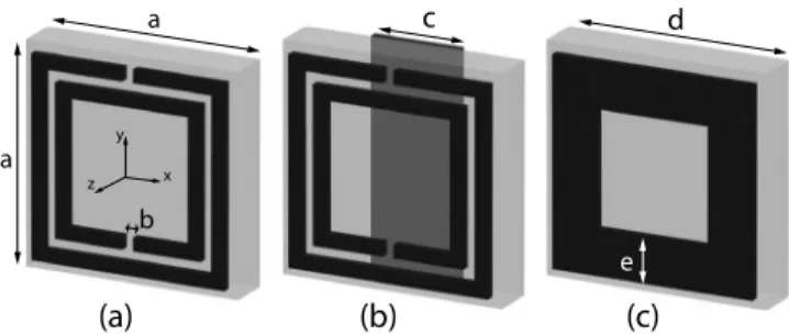
back of the substrate and the square SRRs were on the front faces. The structures were printed on a Teflon substrate with =2.17, in which the thickness of the substrate was 1 mm. The thickness of the copper was 0.05 mm. The width of the wire stripes was 1.6 mm. The lattice constant along the x direction共propagation direction兲 was 4.95 mm. The height of the structure was 40 unit cells. 30 layers of the structures were stacked with a 2 mm period along the z direction. The E-field was in the y direction. The details regarding the unit cell of the metamaterial structures are shown in Figs. 1共a兲 and1共b兲.
We first calculated the effective andof the SRR and CMM structures by use of a retrieval procedure. The re-trieval procedure is widely used to calculate the effective parameters of the metamaterials. In this method, the real and imaginary parts of the refractive index, wave impedance, and, therefore, the real and imaginary parts of the and are retrieved from the amplitude and the phase information of the transmission and reflection. The details of the retrieval procedure that were used in this study are outlined in Ref.7. This particular method has the advantage of identifying the correct branch of the effective and. The ambiguity in the determination of the correct branch is resolved by the use of an analytic continuation procedure. There was one layer of the structure along the propagation direction in this calcula-tion. We employed periodic boundary conditions along direc-tions other than the propagation direction. Therefore, the simulation setup coincides with a slab of material that
con-a兲Electronic mail: [email protected].
e a ( a ) ( b ) ( c ) d c b y z x
FIG. 1. 共a兲 The unit cell of the SRR structure: a=4.95 mm, b=0.25 mm. 共b兲 the unit cell of the CMM structure: c = 1.6 mm.共c兲 the cavity structure: d = 5.4 mm, e = 1 mm. The unit cells of metamaterials are much smaller than the operating wavelength.
APPLIED PHYSICS LETTERS 93, 121910共2008兲
sists of a single layer. The effective and were derived from the transmission and reflection coefficients. The calcu-lated parameters show that the SRR structure possesses ef-fective ⬎0, ⬍0 from 5.0 to 7.0 GHz 关Fig.2共a兲兴. How-ever, the CMM structure possesses effective ⬍0, ⬍0 from 5.4 to 7.0 GHz and ⬍0, ⬎0 from 7.0 to 9.4 GHz 关Fig.2共b兲兴.
The measured transmission spectrum of the SRR exhib-its a band gap between 5.0 and 7.0 GHz 关Fig.3共a兲兴. On the other hand, the CMM structure transmits em waves at the band gap frequency of the SRR关Fig.4共a兲兴, since it has nega-tive and at this range. The simulation results agree well with the measurement. The experimental setup consisted of an HP 8510C network analyzer and two standard gain horn antennae in order to measure the transmission amplitude. The transmission simulations throughout the letter were per-formed by the commercial software program CST MICRO-WAVE STUDIO®.
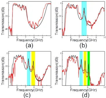
Subsequently, we introduced the defect structure into the left-handed structures and we changed the center unit cell of the structures by a closed ring structure. The total single-cavity system contains one single-cavity at the center and two metamaterial unit cells in each side of the cavity 共1 cavity + 4 metamaterial unit cells兲 in the propagation direction. The defect structure is a closed ring structure, which was placed on both sides of the board and possessed positive and 关Fig. 1共c兲兴. In the presence of a single cavity, a localized cavity mode is observed in the transmission spectrum of SRR and CMM based structures. The measured cavity reso-nance frequencies are ⍀=6.7 GHz and 7.6 GHz 关Figs. 3共b兲 and4共b兲兴.
Moreover, we brought two cavities together with an in-tercavity distance of two metamaterial unit cells. The total two-cavity system contains two cavities and two metamate-rial unit cells in each side of the each cavity 共2 cavities+6 metamaterial unit cells兲 in the propagation direction. For two coupled cavities, the transmission characteristics as a func-tion of frequency are measured and calculated. As shown in Figs. 3共c兲 and 4共c兲, we observed that the resonance modes are split into two distinct symmetric and antisymmetric modes similar to PC cavity structure. In PC cavity structures, when two isolated cavities are brought together, the localized photon modes should overlap. Due to this interaction, the doubly degenerate eigenmode splits into two distinct modes as symmetric and antisymmetric.8These modes are reminis-cent of the bonding and antibonding states in solid state physics. For example, in the diatomic molecules, the interac-tion between the two atoms produces a splitting of the de-generate atomic levels into bonding and antibonding orbitals.9The measured values of resonance frequencies are
1= 6.5 GHz and 2= 6.9 GHz for the SRR based cavity
structure and 1= 7.3 GHz and 2= 7.9 GHz for the CMM
based cavity structure.
When we brought three cavities together with an inter-cavity distance of two metamaterial unit cells, the single cav-ity mode ⍀ splits into three different eigenmodes. In this
5 6 7 8 9 10 -20 -15 -10 -5 0 realε realµ Frequency(GHz) 4 5 6 7 8 9 -10 0 10 20 30 realε realµ Frequency(GHz)
(a)
(b)
FIG. 2. 共Color online兲 共a兲 The calculated parameters show that the SRR structure possesses effective ⬎0, ⬍0 from 5.0 to 7.0 GHz. 共b兲 The CMM structure possesses effective ⬍0,⬍0 from 5.4 to 7.0 GHz and ⬍0,⬎0 from 7.0 to 9.4 GHz 关Fig.2共b兲兴.
( d )
( c )
4 5 6 7 8 9 - 4 0 - 2 0 0 T ra nm is si on (d B ) F r e q u e n c y ( G H z )( b )
4 5 6 7 8 9 - 4 0 - 2 0 0 F r e q u e n c y ( G H z ) Tr an m is si on (d B ) 4 5 6 7 8 9 - 4 0 - 2 0 0 F r e q u e n c y ( G H z ) T ra ns m is si on (d B ) 4 5 6 7 8 9 - 4 0 - 2 0 0 F r e q u e n c y ( G H z ) T ra ns m is si on (d B )( a )
FIG. 3. 共Color online兲 Measured 共red curves兲 and calculated 共black curves兲 transmission spectra for共a兲 SRR and 共b兲 SRR with a single-cavity, 共c兲 two-coupled-cavity, and共d兲 three-coupled-cavity structures. Due to the coupling between the strongly localized cavity modes, the single-cavity mode splits into two or three distinct modes depending on the number of coupled cavi-ties. There is a good agreement between the measured and calculated trans-mission spectra. 6 8 1 0 - 4 0 - 2 0 0 Tr an sm is si on (d B ) F r e q u e n c y ( G H z )
( d )
( c )
( b )
5 6 7 8 9 1 0 - 4 0 - 2 0 0 Tr an sm is si on (d B ) F r e q u e n c y ( G H z ) 5 6 7 8 9 1 0 - 4 0 - 2 0 0 Tr an sm is si on (d B ) F r e q u e n c y ( G H z ) 5 6 7 8 9 1 0 - 4 0 - 2 0 0 Tr an sm is si on (d B ) F r e q u e n c y ( G H z )( a )
FIG. 4. 共Color online兲 Measured 共red curves兲 and calculated 共black curves兲 transmission spectra for共a兲 CMM and 共b兲 CMM with a single-cavity, 共c兲 two-coupled-cavity, and共d兲 three-coupled-cavity structures.
case, the total three-cavity system contains three cavities and two metamaterial unit cells in each side of the each cavity共3 cavities+ 8 metamaterial unit cells兲 in the propagation direc-tion. The corresponding transmission spectra of the system were measured and calculated. As shown in Figs. 3共d兲 and
4共d兲, there is a good agreement between the measured and calculated transmission characteristics of the three coupled cavities. The resonance frequencies were ⌫1= 6.4 GHz, ⌫2
= 6.7 GHz, and⌫3= 7.0 GHz for the SRR based cavity
struc-ture and⌫1= 7.2 GHz,⌫2= 7.6 GHz, and ⌫3= 8 GHz for the CMM based cavity structure.
Recently, the classical wave analog of the TB picture10 has successfully been applied to photonic structures.11 By using the direct implications of the TB picture, a novel propagation mechanism for photons along the localized coupled-cavity modes in PCs was proposed12 and demonstrated.13 In these structures, photons can hop from one tightly confined mode to the neighboring one due to the weak interaction between them. The same approach can be applied to metamaterial based coupled cavities. Using the TB picture, it is possible to obtain eigenvalues and eigenvectors corresponding to two- and three-coupled cavity structures.14 Hence, the dispersion relation and group velocity can be ob-tained, keeping only the nearest-neighbor coupling terms as
共k兲 = ⍀关1 +cos共k⌳兲兴,
g共k兲 = ⵜkk= −⌳⍀ sin共k⌳兲.
Here, is a TB parameter that can be obtained from the splitting of the eigenmodes of two-coupled cavities, in which ⍀ is the frequency mode of the single cavity, and ⌳ is the distance between the two-cavity structures 共intercavity dis-tance兲.
The calculated TB parameters are = −0.05 and
= −0.07 for SRR and CMM based coupled cavities, respec-tively. We can obtain the dispersion relation of the coupled cavity structures by using these TB parameters and ⌳ = 9.9 mm共2 metamaterial unit cells兲. Figure 5共a兲shows the calculated dispersion relations共k兲. We also plotted the nor-malized group velocity corresponding to the coupled-cavity structures. As shown in Fig. 5共b兲, the group velocity has a maximum value of nearly one-hundredth the speed of light in vacuum, at the coupled-cavity band center, and vanishes at the band edges.
As a conclusion, the transmission properties of the coupled-cavity structures in one-dimensional metamaterials have been investigated. The splitting of eigenmodes due to the interaction between the localized electromagnetic cavity modes was observed. The results are very similar to the PC coupled-cavity systems. However, taking the advantage of the subwavelength dimension of the metamaterial system, it is possible to localize fields into subwavelength regions
us-ing SRR and CMM based cavity systems. In takus-ing advan-tage of the TB approach, we calculated the dispersion rela-tion and group velocity of metamaterial based coupled-cavity structures. The group velocity was rather low for these struc-tures. Therefore, the spontaneous emission rate and effi-ciency of the nonlinear processes can be enhanced in metamaterial based coupled-cavity structures.
This work is supported by the European Union under the projects EU-METAMORPHOSE, EU-PHOREMOST, EU-PHOME, and EU-ECONAM, and TUBITAK under the Project Nos. 105E066, 105A005, 106E198, and 106A017. One of the authors 共E.O.兲 also acknowledges partial support from the Turkish Academy of Sciences.
1E. Ozbay and K. Aydin, Photonics Nanostruct. Fundam. Appl. 6, 108
共2008兲.
2I. Bulu, H. Caglayan, and E. Ozbay,Opt. Lett. 31, 814共2006兲. 3J. B. Pendry, A. J. Holden, D. J. Robbins, and W. J. Stewart,J. Phys.:
Condens. Matter 10, 4785共1998兲.
4J. B. Pendry, A. J. Holden, D. J. Robins, and W. J. Stewart, J. Phys.:
Condens. Matter 47, 2075共1999兲.
5D. R. Smith, W. J. Padilla, D. C. Vier, S. C. Nemat-Nasser, and S. Schultz,
Phys. Rev. Lett. 84, 4184共2000兲.
6H. Caglayan, I. Bulu, M. Loncar, and E. Ozbay,Opt. Express 16, 11132
共2008兲.
7X. Chen, T. M. Grzegorczyk, B.-I. Wu, J. Pacheco, Jr., and J. A. Kong,
Phys. Rev. E 70, 016608共2004兲.
8M. I. Antonoyiannakis and J. B. Pendry,Phys. Rev. B 60, 2363共1999兲. 9C. Kittel, Introduction to Solid State Physics共Wiley, New York, 1996兲. 10N. W. Ashcroft and N. D. Mermin, Solid State Physics共Saunders,
Phila-delphia, PA, 1976兲.
11E. Lidorikis, M. M. Sigalas, E. N. Economou, and C. M. Soukoulis,Phys.
Rev. Lett. 81, 1405共1998兲.
12T. Mukaiyama, K. Takeda, H. Miyazaki, Y. Jimba, and M.
Kuwata-Gonokami,Phys. Rev. Lett. 82, 4623共1999兲.
13M. Bayindir, B. Temelkuran, and E. Ozbay, Phys. Rev. Lett. 84, 2140
共2000兲.
14M. Bayindir, C. Kural, and E. Ozbay,J. Opt. A, Pure Appl. Opt. 3, 184
共2001兲. 0.0 0.5 1.0 0.9 1.0 1.1 kΛ/π ω (k )/ Ω 0.0 0.5 1.0 0.000 0.004 0.008 0.012 kΛ/π vg (k )/ c
(a)
(b)
FIG. 5.共Color online兲 共a兲 The calculated dispersion relation of the coupled-cavity structures is shown共black curves stand for the SRR based cavity and the red curves stand for the CMM cavity structure兲. 共b兲 The group velocity is two orders of magnitude smaller than the speed of light at the band center 共k⌳=/2兲 and vanishes at the band edges 共k⌳=0 and兲.