Sayı 18, S. 213-223, Mart-Nisan 2020
© Telif hakkı EJOSAT’a aittir
Araştırma Makalesi
www.ejosat.com ISSN:2148-2683No. 18, pp. 213-223, March-April 2020
Copyright © 2020 EJOSAT
Research Article
Rapid Prototype Development of Single-Phase Grid-Connected PV
Inverter Using STM32F4 and Matlab
Süleyman Yarıkkaya
1, Kadir Vardar
2*1 Afyon Kocatepe University, Dinar Vocational School, Computer Programming, Afyonkarahisar, Turkey (ORCID: 0000-0003-1582-6588)
2 Kütahya Dumlupınar University, Engineering Faculty, Department of Electrical and Electronics Engineering, Kütahya, Turkey (ORCID: 0000-0002-0197-0215)
(İlk Geliş Tarihi 27 Ocak 2020 ve Kabul Tarihi 22 Şubat 2020) (DOI: 10.31590/ejosat.680586)
ATIF/REFERENCE: Yarıkkaya, S. & Vardar, K. (2020). Rapid Prototype Development of Single-Phase Grid-Connected PV Inverter Using STM32F4 and Matlab. Avrupa Bilim ve Teknoloji Dergisi, (18), 213-223.
Abstract
In this paper, the program source code of the STM32F407 microcontroller for PV (photovoltaic) inverter circuit was tested using Simulink before applying it to a power electronics circuit. Firstly, a single-phase grid-connected PV (photovoltaic) inverter structure is modeled in Matlab / Simulink environment. In the light of these simulation results, the control blocks of the inverter are programmed using the MikroC ARM compiler for the STM32F407 microcontroller. Before the circuit design stage, a model was developed to work with Matlab / Simulink in order to prevent possible errors and losses of the microcontroller code of the designed PV inverter. This model includes power electronics semiconductors and passive components, PV panels, grid and data communication blocks. The C source code containing the inverter control blocks (MPPT, PLL, DC Link PI and Current controller) are loaded into the STM32F4 Discovery kit. At each step of the simulation, the current and voltage information obtained from the Matlab model is sent to the STM32F4 kit via serial communication. The current and voltage information is processed in microcontroller software and switching pulses of IGBTs are created and transferred back to Matlab model. In this way, a rapid and secure prototype hardware development method is presented with the joint operation of Matlab and STM32F4. The results obtained from the simulation and Matlab-STM32F4 joint study are given comparatively.
Keywords: PV inverter, Matlab, STM32F4, Rapid Prototype.
STM32F4 ve Matlab Kullanılarak Tek Faz Şebeke Bağlantılı PV
İnverterin Hızlı Prototip Geliştirilmesi
Öz
Bu çalışmada, PV (photovoltaic) inverter devresi için STM32F407 mikrodenetleyicisine ait oluşturulan program kaynak kodunun bir güç elektroniği devresine uygulanmadan önce Simulink kullanılarak testi gerçekleştirilmiştir. Öncelikle, tek faz-şebeke bağlantılı bir PV (photovoltaic) inverter yapısı Matlab / Simulink ortamında modellenmiştir. Bu simülasyon sonuçları ışığında inverterin kontrol blokları STM32F407 mikrodenetleyici için MikroC ARM derleyicisi kullanılarak programlanmıştır. Tasarlanan PV invertere ait mikrodenetleyici kodunun devre tasarım aşamasına geçmeden önce olası hata ve kayıpların önüne geçmek amacıyla Matlab/Simulink ile birlikte çalışabilmesi için bir model oluşturulmuştur. Bu model, güç elektroniği yarıiletken ve pasif elemanları, PV paneller, şebeke ve veri haberleşmesi gerçekleştiren blokları içermektedir. İnverter kontrol bloklarını (MPPT, PLL, DC Link PI ve Akım kontrolcüsü) içeren C kaynak kodu STM32F4 Discovery kitine yüklenmiştir. Simülasyonun her bir adımında Matlab modelinden elde edilen akım ve gerilim bilgileri, seri iletişim ile STM32F4 kitine yollanmaktadır. Akım ve gerilim bilgileri mikrodenetleyici yazılımında işlenmekte ve IGBT’lere ait anahtarlama palsleri oluşturulup tekrar Matlab modeline aktarılmaktadır. Bu şekilde Matlab ve STM32F4 ortak çalıştırılması ile hızlı ve güvenli bir prototip donanım geliştirme yöntemi sunulmuştur. Simülasyon ve Matlab-STM32F4 ortak çalışmasından elde edilen sonuçlar karşılaştırmalı olarak verilmiştir.
* Sorumlu Yazar: Kütahya Dumlupınar University, Engineering Faculty, Department of Electrical and Electronics Engineering, Kütahya, Türkiye, ORCID: 0000-0002-0197-0215, [email protected]
Anahtar Kelimeler: PV inverter, Matlab, STM32F4, Hızlı Prototip.
1. Introduction
Renewable energy is a good alternative to supply global energy needs. Technological developments play an important role in the transition from fossil fuel consumption to renewable energy. Technological developments are increasing rapidly with the researches in this field in recent years (Reis et al., 2015). It is an advantageous solution to transfer the energy produced in small power PV systems to the grid via single phase (Arafa, Mansour, Sakkoury, Atia, & Salem, 2016). Power electronics elements are used for the safe connection of renewable energy sources (Tsengenes & Adamidis, 2011). With digitalization, an increasing trend in power electronics, the use of DSPs (Digital Signal Processors) in inverters has increased rapidly. The software of DSPs used in control systems has also become more complex with the developing control algorithms. With the traditional design methods, the control process is extending due to both the use of documentation and coding errors. For this reason, design and development processes and various modeling structures have been established (Castoldi, Aguiar, Azauri, & Monteiro, 2006; Vardar, Sürgevil, & Akpinar, 2009; Zhang, Zhang, Wang, & Pan, 2010; Durbaba, Akpinar, Balıkcı, Azizoğlu, & Kocamış, 2019).
In the design and development process of a power electronics, system simulations are used. The simulations allow software operation without damaging any power electronics element or controller (Model in the Loop-MIL). From the simulated design to the application stage, the necessary controller software is made for the controller. If it is possible to run the controller software in the simulation, the test is performed by embedding the source code in the simulation (Software in the Loop-SIL). This makes it possible to verify the software. If the simulation software does not have the ability to process source code, the controller source code is loaded into the microprocessor/microcontroller hardware. The controller and the simulation are run jointly by sharing data (Processor in the Loop-PIL). Thus, the controller is tested by connecting to the simulation instead of the actual system (Moreira, 2015).
In this study, hysteresis current controlled single-phase grid-connected PV inverter was designed and the microcontroller source code was created quickly and safely by applying MIL and PIL stages. First, a single-phase grid-connected PV inverter was simulated using Matlab / Simulink. Then the source code of the software for the STM32F407 microcontroller was prepared using the MikroC Pro for ARM compiler to run the controller algorithm STM32F4 Discovery kit designed in the simulation. The control part was removed from the simulation and replaced with an S-function block to communicate with the STM32F407 microcontroller. This block enables data communication between Matlab/Simulink and STM32F4 kit. The power electronics elements and the grid part work on Matlab/Simulink, while the controller part physically works on the STM32F4 Discovery kit. The current and voltage information obtained from the power part in Simulink model are sent to the microcontroller and the gate control signals obtained from the microcontroller output are taken to Simulink and applied to the model. Thus, the development of the microcontroller code of the designed PV inverter has been completed and its accuracy has been tested safely.
In this study, single-phase grid-connected PV inverter structure and features are presented in the second chapter. In Section 3, simulation block structures of PV inverter modeled with Matlab/Simulink are given. The simulation structure created by Matlab/Simulink and STM32F407 microcontroller is in Section 4. In Section 5, the results of the MIL and PIL simulations performed are presented and compared.
2. Single-Phase Grid-Connected PV Inverter
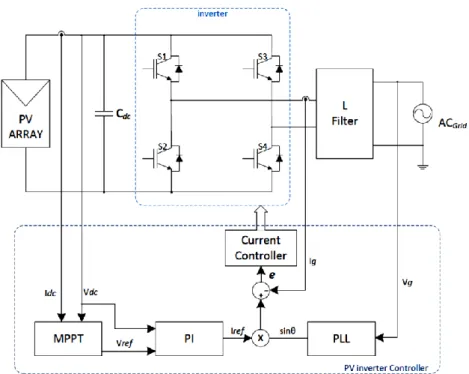
PV systems are one of the most important renewable energy systems. These systems generate DC energy and this energy must be converted to AC energy to be transferred to the grid. For this purpose, inverter circuits that convert DC energy to AC energy are used (Hannan, Abd Ghani, & Mohamed, 2010). Inverters are one of the most important devices in grid-connected PV systems because they provide power conversion and grid synchronization (Jana, Saha, & Das Bhattacharya, 2017). The general structure of the single-phase grid-connected PV inverter is given in Figure 1. In this study, a voltage controlled, current controlled h-bridge inverter structure is used. In this structure, the DC voltage produced by the PV array is kept in balance with the CDC capacitor and the fluctuations are suppressed.
This DC voltage is then connected to the inverter input. Here, both the input voltage and the output current are controlled by the power stage formed by 4 semiconductor switching elements (Insulated Gate Bipolar Transistor-IGBT). The voltage level of the inverter input is determined by the MPPT (maximum power point tracking) algorithm. With the L filter used between the inverter and the grid, the inverter output current is filtered into a sinusoidal structure and transferred to the grid.
Figure 1. Single-phase grid-connected PV inverter block diagram.
Because of the PV panel current and voltage characteristic curves are not linear, the power to be obtained from the PV panels varies according to the drawn current and voltage of the panel. When the maximum power is drawn from the PV panels, the intersection point of the voltage obtained with the current drawn is called the maximum power point (MPP). The maximum power point varies depending on environmental factors such as temperature and radiation. For this reason, various MPPT algorithms are used to tracking the MPP and enable the PV panels to operate at the maximum power point. One of the well-known and commonly used algorithms among these algorithms is the Perturb and Observation (P&O) algorithm (Gupta & Saxena, 2016).
The DC link reference voltage value obtained from the MPPT block is followed by a DC link controller designed by using the PI controller structure. In this block, the reference voltage value is subtracted from the DC link voltage value and the error value is obtained. When the calculated error is applied to the input of PI controller, the reference inverter current value is produced at the output of the controller. PI controller is preferred for DC link control due to its good dynamic performance. The transfer function GPI used for the PI
controller is given by equation (1). 𝐺𝑃𝐼(𝑠) = 𝐾𝑝+
𝐾𝑖
𝑆 (1)
With the PLL structure, phase angle information is obtained by monitoring the grid voltage and a unit sine wave is generated at the output of the block in the same phase as the grid. The reference current amplitude, which is the output of the DC link controller, is multiplied by the unit sine wave generated by the PLL to obtain the inverter output reference current. In this way, the inverter output current is synchronized with the grid voltage. (Ciobotaru, Teodorescu, & Blaabjerg, 2006).
The control block section starts with the MPPT block, where maximum power point tracking (MPPT) is performed. This block provides maximum power from PV panels. After the MPPT block, the DC link PI controller and PLL blocks are used to generate the inverter reference current value. Finally, a Current Controller is used to generate switching signals for semiconductors.
3. MIL Simulation Model of PV Inverter
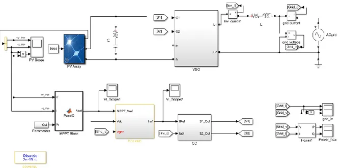
The grid-connected PV inverter simulation created in Matlab / Simulink is given in Figure 2. In this simulation, a PV array consisting of 13 solar panels connected in series to a single arm was used. The maximum power of this PV array is 3968 W. It can supply this power to the system when DC link current value is 5.58 A and voltage value is 711.1 V. A 3300 µF capacitor is connected to reduce the DC voltage fluctuations in the PV panel output. There is a 3mH series inductance at the output of the inverter in order to filtering the inverter output current and providing the grid connection. The sampling time for the simulation is set to 20 µs. The sampling time of the control blocks was determined to 2 ms to suit a real system.
Figure 2. PV inverter simulation with Matlab / Simulink.
In the model created in Matlab / Simulink, the power part is generated using a single-phase H-bridge inverter structure in the VSC (Voltage Source Converter) block (Figure 3). IGBT (Insulated Gate Bipolar Transistor) semiconductors are chosen as the switching elements. Here, the pins p and n are the DC link inputs of the converter circuit. The DC energy produced in the panels is converted to AC voltage at the inverter output and transferred to the grid via L1 and L2 inductors. Inputs G1 and G2 are IGBT trigger terminals.
Figure 3. VSC block structure created in simulation.
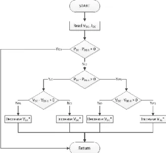
In this study, perturb and observation algorithm is used for tracking the maximum power point. The flow chart of the designed algorithm is given in Figure 4. In this method, panel operating voltage and current values are measured periodically and instantaneous DC link power (PDC) is calculated. The calculated instantaneous power is compared with the previous output instantaneous power. If
the output power increases by increasing the operating voltage, the operating reference voltage is increased. If the output power decreases by increasing the operating voltage, the operating reference voltage is decreases. The main advantage of this technique is that it is very simple and easily applicable. The disadvantage is that the working point oscillates at a high rate around the MPP point and is not exactly constant at the MPP point (Selvan, Nair, & Umayal, 2016).
Figure 4. Perturb and observation algorithm flow chart.
DC link reference voltage value is generated from MPPT block output. In the MPPT algorithm, there are lower limit, upper limit, initial value and change amount (ΔV) parameters for DC link reference voltage value to be produced. The parameter values used in this study are 600V, 720V, 700V and 0.5V, respectively.
In the simulation, both the PI controller and the PLL block are included in the DC Link Controller block. Reference DC link voltage value (VDC*) generated in MPPT block, grid voltage value (VGrid) and DC Link voltage value (VDC) are entered in the block and reference
current value (Iref) is generated. Figure 5 shows the structure of the DC Link Controller block.
Figure 5. DC Link Controller block structure in simulation.
In this study, a hysteresis controller is used as the current controller (CC) and the block diagram is given in Figure 6. With this controller by comparing the current reference value obtained from the DC Link Controller block output and the current value read from the inverter output, inverter control signals (S1 and S2) are produced, which enable it to hold within ± 1A hysteresis band.
Figure 6. Current controller block structure in simulation.
4. PIL Simulation Model of PV Inverter
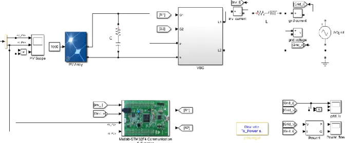
In order to develop safe and rapid prototypes, the simulation block diagram with the PIL structure created using Matlab / Simulink is given in Figure 7. Unlike the MIL simulation, the control blocks (MPPT, DC Link Controller and Current Controller) were removed and replaced with the Matlab-STM32F4 S-function block. This block provides communication between the Matlab / Simulink program and STM32F4 using the UART communication protocol. In each step of the Matlab simulation, the inverter output current (inv_i), grid voltage (Grid_V), PV panel output current (I_PV, IDC) and PV panel output voltage (V_PV, VDC) values which are inputs of the
communication block, are sent to the microcontroller. The switching data (S1 and S2) for controlling the inverter, which is the output of the communication block, is read from microcontroller. With this structure, the co-operation work between STM32F4 and Simulink is established.
Figure 7. Matlab and STM32F4 joint work Simulation.
The flow chart showing the general working logic of this structure is given in Figure 8. The controller part is operated in the STM32F4 Discovery kit. On the computer side; grid, PV panels, semiconductor inverter circuits and measuring circuits were modeled using Matlab / Simulink program. The system is first started by running the model created in Matlab / Simulink on the computer. At each step of the simulation; current and voltage values are obtained by analyzing power electronics circuits. The obtained values are sent to the STM32F4 Discovery kit using the UART communication protocol by s-function block. The STM32F4 Discovery Kit generates the IGBT gate switching signals by running the control algorithm after reading this incoming data. The generated switching data is sent back to Matlab / Simulink model by using UART communication protocol. IGBT switching states are updated with this received data by Matlab / Simulink program. With the updated switching data, the simulation runs another iteration step for obtaining new inverter current and voltage values. These new current and voltage values are sent back to the microcontroller kit and the system continues to run cyclically.
Figure 8. General flow chart of PIL simulation structure.
In each iteration step in Matlab / Simulink, the S-Function block runs once. With this block, the communication port of the computer is reached and communication is made with STM32F4 discovery kit. After the S-function block runs, the block input data is sent to the STM32F4 kit via communication and the switching data is expected from the kit. If no switching data is received within 10 seconds,
The kit has 1 mini USB port and 1 micro USB port. These ports are available for programming, communication for applications and debugging mode. The development board has 4 USART (universal synchronous / asynchronous receiver transmitters) and 2 UART (universal asynchronous receiver transmitters) units for serial communication.
Figure 9. STM32F4 Discovery kit.
In this study, serial communication was carried out using the UART4 unit. PC10 and PC11 pins were assigned as transmit (Tx) and receive (Rx) pins, respectively. The PC connection with this kit was made via a USB-RS232 converter. Serial communication was used with one stop bit, no parity bit, 8-bit data and 115200 bps (bit per second).
The C source code containing inverter control blocks (MPPT, PLL, DC Link PI and Current controller) has been prepared using the MikroC ARM compiler. The MikroC source code for the generated PIL simulation is given in the Appendix 2.
5. MIL and PIL Simulation Results of PV Inverter
In the MIL and PIL simulation studies, PV panel temperature is set to 25 ºC and radiation intensity is set to 1000 W/m2. DC link PI controller parameter values are used as Kp = 0.3 and Ki = 2.5.
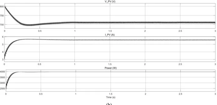
As a result of MIL simulation of PV Inverter, the graphs of current, voltage and instantaneous power obtained from PV panel output are given in Figure 10a. The PV panel output voltage is also the DC link voltage of the inverter. When the graphs are examined, it is seen that the transient state lasts about 1 second and the state is switched to steady state after 1 second. The output voltage of the PV panel decreases to 697 V in transient state and operates steady state at 712 V after approximately 1 second. In the transient state, the maximum value of PV inverter current passing through the panels is 5.67 A. In the steady state, the value of panel current is 5.57 A. When the instantaneous power graph is examined, it is seen that the transferred power from the PV panels to grid is between 3965-3968 W in steady state. The current, voltage and instantaneous power graphs of the PV panel output obtained from the PIL simulation study of the PV Inverter are given in Figure 10b. When the graphs of PIL and MIL simulations are compared, it is seen that the results are approximately similar to each other.
(b)
Figure 10. PV Inverter DC Link voltage, current and power values a) MIL simulation b) PIL simulation
The graphs of the power values transferred to the grid by a single-phase grid-connected PV inverter are given in Figure 11a and Figure 11b. In both simulation models, it is seen that the transient power value increases above 4800 W and goes to steady state within 1.3 sec. In steady state, 3920 W of power is transferred to the grid. When the power transmission graph of MIL simulation is examined in Figure 11a, no oscillation is seen in steady state.
(a)
(b)
Figure 11. Inverter output power a) MIL simulation b) PIL simulation
In the transferred power graph of the PIL simulation in Figure 11b, small oscillations are observed with 20W amplitude in continuous state. These small oscillations are thought to be due to the fact that Matlab/Simulink and STM32F407 have different decimal
References
Arafa, O. M., Mansour, A. A., Sakkoury, K. S., Atia, Y. A., & Salem, M. M. (2016). Realization of single-phase single-stage grid-connected PV system. Journal of Electrical Systems and Information Technology, 4(1), 1–9. https://doi.org/10.1016/j.jesit.2016.08.004
Castoldi, M. F., Aguiar, M. L., Azauri, A. O., & Monteiro, J. R. B. A. (2006). A rapid prototype design to investigate the FPGA - Based DTC strategy applied to the speed control of induction motors. Proceedings of the IEEE International Conference on Industrial Technology, 955–960. https://doi.org/10.1109/ICIT.2006.372304
Ciobotaru, M., Teodorescu, R., & Blaabjerg, F. (2006). Control of single-stage single-phase PV inverter. EPE Journal (European Power Electronics and Drives Journal), 16(3), 20–26. https://doi.org/10.1080/09398368.2006.11463624
Gupta, A. K., & Saxena, R. (2016). Review on widely-used MPPT techniques for PV applications. 1st International Conference on Innovation and Challenges in Cyber Security, ICICCS 2016, 270–273. https://doi.org/10.1109/ICICCS.2016.7542321
Hannan, M. A., Abd Ghani, Z., & Mohamed, A. (2010). An enhanced inverter controller for PV applications using the dSPACE platform. International Journal of Photoenergy. https://doi.org/10.1155/2010/457562
Jana, J., Saha, H., & Das Bhattacharya, K. (2017). A review of inverter topologies for single-phase grid-connected photovoltaic systems. Renewable and Sustainable Energy Reviews, 72 (November 2016), 1256–1270. https://doi.org/10.1016/j.rser.2016.10.049 Moreira, C. O. (2015). Rapid Control Prototyping Using an STM32 Microcontroller.
Reis, G. L., Mata, P. C. A., Silva, W. W. A. G., Silva, R. M., Martins, A. L. N., Fernandes, V. A., & Silveira, E. P. (2015). Design and implementation of a prototype of a single phase converter for photovoltaic systems connected to the grid. IEEE 13th Brazilian Power Electronics Conference and 1st Southern Power Electronics Conference, COBEP/SPEC 2016, 1–6. https://doi.org/10.1109/COBEP.2015.7420293
Selvan, S., Nair, P., & Umayal, U. (2016). A Review on Photo Voltaic MPPT Algorithms. International Journal of Electrical and Computer Engineering (IJECE), 6(2), 567. https://doi.org/10.11591/ijece.v6i2.9204
Tsengenes, G., & Adamidis, G. (2011). Investigation of the behavior of a three phase grid-connected photovoltaic system to control active and reactive power. Electric Power Systems Research, 81(1), 177–184. https://doi.org/10.1016/j.epsr.2010.08.008
Vardar, K., Sürgevil, T., & Akpinar, E. (2009). Rapid prototyping applications on three-phase PWM rectifier and shunt active power filter. ELECO 2009 - 6th International Conference on Electrical and Electronics Engineering, 258–262. https://doi.org/10.1109/ELECO.2009.5355298
Zhang, W., Zhang, Y., Wang, R., & Pan, X. (2010). A model-based DSP control platform for rapid prototype of SVPWM. International Conference on Signal Processing Proceedings, ICSP, 2523–2526. https://doi.org/10.1109/ICOSP.2010.5656854
Durbaba, E., Akpinar, E., Balıkcı, A., Azizoglu, B. T., & Kocamis, A. E. (2019). Fast Prototyping of A Photovoltaic System by Using DSP in MATLAB Simulation Loop, IECON 2019 - 45th Annual Conference of the IEEE Industrial Electronics Society, Lisbon, Portugal, 1768-1773, https://doi: 10.1109/IECON.2019.8926786
Appendix-1
function STM32F4(block) global s, a setup(block); function setup(block) global s, a s = serial('COM3'); s.InputBufferSize=128; s.BaudRate=115200; s.FlowControl='none'; s.DataBits=8; s.StopBits = 1; s.Terminator = 'LF'fopen(s);
%% Register number of input and output ports block.NumInputPorts = 4; block.NumOutputPorts = 2; block.SetPreCompInpPortInfoToDynamic; block.SetPreCompOutPortInfoToDynamic; block.InputPort(1).Complexity = 'Real'; block.InputPort(1).DataTypeId = 0; block.InputPort(1).Dimensions = 1; block.InputPort(1).SamplingMode = 'Sample'; …. block.SampleTimes = [-1 0]; block.SetAccelRunOnTLC(true); block.RegBlockMethod('Outputs', @Output); function Output(block) global s, a Iact=(block.InputPort(1).Data); Vgrid=(block.InputPort(2).Data); PV_Vout=(block.InputPort(3).Data); PV_Iout=(block.InputPort(4).Data); fprintf(s,'%9.4f',Iact); %send data fprintf(s,'%9.3f',Vgrid);
fprintf(s,'%9.3f',PV_Vout); fprintf(s,'%9.3f\n',PV_Iout);
RecDataStr =fscanf(s,'%c'); %read charecter data StrReceive=strsplit(RecDataStr,','); ReceiveData1=str2double(StrReceive(1)); ReceiveData2=str2double(StrReceive(2)); block.OutputPort(1).Data = ReceiveData1; block.OutputPort(2).Data = ReceiveData2;
Appendix-2
Void main(){ UART4_Init_Advanced(115200,_UART_8_BIT_DATA,_UART_NOPARITY,_UART_ONE_STOPBIT,&_GPIO_MODULE_UART 4_PC10_11);if (UART4_Data_Ready() ) { // if data is received
UART4_Read_Text(ReceiveBuffer, "\n", 64); // reads text until '\n' newline strncpy(Iacttxt, ReceiveBuffer, 9); // read first 9 charecter strncpy(Vgridtxt, ReceiveBuffer +9, 9); // read second 9 charecter strncpy(PV_Vouttxt, ReceiveBuffer +18, 9);
strncpy(PV_Iouttxt, ReceiveBuffer +27, 9);
Iact= atof(Iacttxt) ; Vgrid= atof(Vgridtxt) ; // convert to double PV_V= atof(PV_Vouttxt) ; PV_I= atof(PV_Iouttxt) ;
TimeCount++ ; if(TimeCount >= 100){ TimeCount =0; pv_P= pv_V * pv_I ; Dpv_V= pv_V - pv_Vold; Dpv_P= pv_P - pv_Pold; if (Dpv_P != 0){ if (Dpv_P < 0) {
if (Dpv_V < 0) MpptVref = MpptVrefold + deltaV; else MpptVref = MpptVrefold - deltaV; } else {
if (Dpv_V < 0) MpptVref = MpptVrefold - deltaV; else MpptVref = MpptVrefold + deltaV; } }
if (MpptVref >= Vmax || MpptVref<= Vmin) MpptVref=MpptVrefold; MpptVrefold=MpptVref; pv_Vold=pv_V; pv_Pold=pv_P; }
vdc_error=PV_V-MpptVref ;
Kpvalue= Kp*( vdc_error - vdc_errorOld); Kivalue= Ki*( vdc_error);
Iref=IrefOld + Kpvalue + Kivalue ; vdc_errorOld = vdc_error; IrefOld=Iref; PLLOut=Vgrid/310.0 ; IrefAc=PLLOut*Iref; I_error =IrefAc-Iact; if(I_error>1) { Swh1=1; Swh2=0; } else if(I_error <-1) { Swh1=0; Swh2=1; } SendBuffer1 [0]=48+Swh1;
SendBuffer1 [1]=44; // comma character SendBuffer1 [2]=48+Swh2;
SendBuffer1 [3]=44; // Add termination character LF UART4_Write_Text(SendBuffer1); // sends back text