Contents lists available at ScienceDirect
International Journal of Refractory Metals
& Hard Materials
journal homepage: www.elsevier.com/locate/IJRMHM
Stress, strain and strain-rate cemented carbide properties determined with a
fem-supported evaluation of impact test imprints
Antonios Bouzakis
a, Georgios Skordaris
b, Konstantinos-Dionysios Bouzakis
b,c,⁎,
Mehmet-Gökhan Gökcen
c, Apostolos Boumpakis
b, Ahmet-Ugur Batuk
c, Süleyman Sisman
ca Impact–BZ Ltd, London, United Kingdom
b Laboratory for Machine Tools and Manufacturing Engineering, Mechanical Engineering Department, Aristotle University of Thessaloniki, Greece c Turkish-German University in Istanbul, Turkey
A R T I C L E I N F O Keywords:
Cemented carbide Stress-strain Strain-rate
Constitutive flow curves
A B S T R A C T
Cemented carbide materials are key in tool manufacturing, nowadays widely used in cutting, forming and other manufacturing processes. Commonly applied methods for obtaining their strain-rate dependent material prop-erties are insufficient due to the high hardness, mechanical strength and low deformability. In this paper, we produce relevant data for stress-strain and strain-rate curves up to strain rates of approximately 200 s−1 with the
aid of a developed FEM-supported evaluation method for remaining imprints on cemented carbide surfaces after applying impact loads at various durations and magnitudes. Regarding the impact duration, the impact loads were dynamically generated via electromagnetic or piezoelectric devices. The attained data are relevant to several applications including calculations to determine the stress and strain fields developed in cemented carbide tools imposed by impact loads at various conditions.
1. Introduction
Stress-strain properties of coatings and cemented carbide materials can be attained at ambient and elevated temperatures by evaluating nanoindentation results through a FEM supported algorithm [1,2]. However, these data are associated with the occurring low deformation rates while a typical diamond nano indenter tip slowly penetrates into the material under test. To overcome this problem, we employed the remaining imprints on the specimen surfaces after the impact test at strain rates up to 200 s−1. More specifically, the underlying idea to use
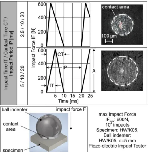
the repetitive impact test to determine stress-strain, strain-rate-depen-dent material properties, derives from the fact that the surface de-formation of a specimen falls as the impact time decreases at constant impact force. This can be observed in the example demonstrated in Fig. 1. The related experiments were conducted with the aid of a pie-zoelectric impact tester, as described in the next section. For an impact force of 600 N at distinct impact times of 5 ms and 2.5 ms, exercised on a cemented carbide surface, the contact area between the ball indenter
and the loaded surface is comparably smaller in the case of the shorter impact time, as depicted in Fig. 1. In this way, if the loaded surfaces are plastically deformed, the remaining imprint depth at the shorter impact time decreases as well. The remaining imprint depth can be accurately measured via confocal microscopy, as described in the following sec-tions.
In the present paper, considering the stress-strain curve of a ce-mented carbide specimen at low deformation rates, i.e. long deforma-tion times, as it is the case during the nanoindentadeforma-tion, the remaining imprint depths (RID) on plastically deformed surfaces after impact testing at various impact loads and times (IT) were calculated and compared with corresponding measured ones. The applied cemented carbide stress-strain data, determined at low deformation rates via a developed algorithm, were stepwise adjusted until the measured RIDs at certain ITs converged with the respective calculated ones. In this way, it was possible to associate stress and strain data with strain-rates. The produced stress, strain and strain-rate data of the tested ce-mented carbide were used to predict the stress and strain distributions,
⁎Corresponding author at: Laboratory for Machine Tools and Manufacturing Engineering, Mechanical Engineering Department, Aristotle University of
Thessaloniki, Greece.
E-mail addresses: [email protected] (A. Bouzakis), [email protected] (G. Skordaris), [email protected] (K.-D. Bouzakis),
[email protected] (M.-G. Gökcen), [email protected] (A. Boumpakis), [email protected] (A.-U. Batuk), [email protected] (S. Sisman).
T
as well as the imprint depths developed in a cemented carbide during the loading and relaxation impact test phase for various impact times. The related calculations were carried out by means of a FEM simulation of the repetitive impact test at different impact loads and times in order to validate the corresponding experimental results.
2. Experimental and numerical methods
The surface response of various materials can be investigated at various repetitive impact loads and times using the devices presented in the publications [3,4]. Using an electromagnetic impact tester, impact times less than approximately 1.5 ms can be realized [3], whereas, via a piezoelectric one, impact times longer than about 2 ms up to few dec-ades of ms can be selectively adjusted [4]. Fig. 2a illustrates the me-chanical units of the electromagnetic and piezoelectric impact testers used in the described investigations, as well their applicable impact time (IT) ranges. These devices manufactured by the Impact-BZ Ltd., among others, allow the adjustment of the impact force IF at varying amplitudes. In addition, control modules comprising personal compu-ters (PC) equipped with convenient hard- and softwares, supervise the whole experimental procedure in both device cases. The time course of an impact force signal at 1200 N created by the electromagnetic impact tester is illustrated in Fig. 2b. The signal grows almost linearly versus the impact time, reaching its maximum value at approximately 0.45 ms
impact time in the present indenter-specimen material case. The time course remains constant in the sequential impacts, as it can be observed in Fig. 2c. This happens in both impact tester devices and independent from the impact time duration.
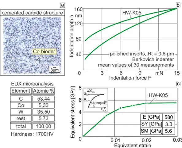
In the described investigations, the selected material for the ball indenter and specimens was fine structured (average grain size 1–1.3 μm) cemented carbide inserts of SPGN/HW K05 ISO specifica-tions [5,6]. The material structure and its chemical composition are illustrated in Fig. 3a. The Vickers hardness of 1700 HV is according to the dependence of hardness on the WC grain size and cobalt content introduced in [6]. K05 is commonly used in cemented carbide coated cutting tool applications.
Stress-strain and strain rate data of this material, enable among others the analytical description of the effect that the substrate imposes on the developed stress fields in the compound coating-substrate, during the impact test when the ball indenter penetrates into the coated specimen at impact loads of short duration [7]. For determining the mechanical properties of the applied K05 cemented carbide at quasi static loads, nanoindentations were conducted by a Fischer scope H100 device. The obtained results are illustrated in Fig. 3b. The shown curve represents the mean value of 30 measurements. In the performed in-vestigations, after 20 indentations, the measurements mean value was stabilized [2]. The indentation curve recorded during the loading stage is digitalized in i Fi-hi pairs. These are the input data to a FEM algorithm
Fig. 3. (a): Material data of the used ball indenter and specimens. (b): Results of nanoindentation on the applied cemented carbide. (c): The determined stress-strain data of the employed cemented carbide.
simulating the diamond indenter penetration into a specimen for de-termining the corresponding stress-strain curve of the specimen mate-rial, as described in the literature [1]. In the beginning of this algo-rithm, the first pair of the applied force F1 and the consequent
penetration depth h1 are considered. Assuming an initial value for the
first tangent modulus M1 of the specimen stress-strain curve
corre-sponding to its elasticity modulus, a penetration force FFEM1 is
de-termined associated with the depth h1 and a maximum von Mises stress
S1max and strain ε1max. If FFEM1 deviates from the measured one F1 more
than a prescribed tolerance, then the value M1 is approximated again
and the FEM solution is repeated. In case that F1 lies within the
toler-ance range, the value M1 is stored and the next values pair F2-h2 is
applied to the model. The next calculation step now starts at an in-dentation depth h1, considering the already existing coating stress
status as well as the previously obtained tangent modulus M1 and ends
at the penetration depth h2. The calculated FFEM2 is compared to the
measured F2 one, and if necessary, the tangent modulus of the specimen
material stress-strain curve over its S1max, ε1max point is conveniently
modified to M2. Otherwise, the tangent modulus M1 remains valid. The
previously described procedure is repeated until the last pair of values Fi-hi are considered and the algorithm ends. The indicated points of the
stress-strain curve exhibited in Fig. 3c, delimit n regions of constant tangent moduli, which approach the inclinations of this curve in the associated von Mises stress-strain ranges. The number n of constant tangent moduli regions depends on the tolerance size when comparing the FiFEM to the related Fi values in the previously described algorithm.
The determined elasticity modulus, i.e. the first tangent modulus of the stress-strain curve, the yield and rupture stress of the K05 specimen are displayed in the table of Fig. 3c. These data for both the cemented carbide ball indenter and specimen were employed in the FEM calcu-lations for predicting the remaining imprint depth at impact times longer than 10 ms, as explained in the following sections.
The developed imprints on the specimen surfaces after the impact tests were captured by 3D measurements using the confocal system μSURF of NANOFOCUS AG.
The axisymmetric 3D-FE model illustrated in Fig. 4a was used for Fig. 4. (a): The impact test FEM supported simulation (itFEMs). (b): Calculated course of the impact force versus the indentation depth during loading and relaxation. (c): Determined Remaining Imprint Depth (RID) depended on the applied maximum Impact Force IFmax.
calculating the surface response at quasi static loads [4]. This model was developed on the ANSYS simulation platform. Contact elements were used for describing the interface between the ball indenter and the specimen surface. The FE model dimensions, material properties, boundary conditions, number of elements, etc., are adjustable para-meters for a flexible consideration of all random conditions. In three- dimensional stress-strain problems, the material status is oriented as per the position of the principal stress vector relative to the yield surface. In general, the two available hardening rules are the isotropic and the kinematic one [8]. In the first case the yield surface remains centered around its initial center and expands in size as the plastic strain de-velops. On the other hand, the kinematic hardening assumes that the yield surface remains constant in size and the surface translates in stress space with progressive yielding, whereas the Besseling model, also called sub-layer or overlay model, is used to characterize the material behavior [8,9]. The previously described FEM model was solved for both plasticity models and the corresponding results were almost
identical. Considering that the kinematic hardening rule leads to a rapid convergence in the corresponding FEM calculations, this method was adopted in further calculations. The described FEM model was also employed in the case of coated specimens, presented in numerous publications, as for example in [3,4,7].
The course of the impact force IF versus the indentation depth ID onto the specimen surface, during loading and relaxation, can be de-termined using the presented FEM–model, as illustrated in the diagram of Fig. 4b. In this way, via repetitive calculations, the remaining imprint depth RID on the specimen surface associated with the corresponding maximum Impact Forces IFmax can be predicted and graphically
pre-sented, as in Fig. 4c. Such diagrams were considered in the developed algorithm to determine stress, strain, and strain-rate dependent mate-rial data, as introduced in the following section. Moreover, the indenter ball deformation during loading and relaxation versus the impact force can be predicted. A related example is also presented in the following section.
3. Results and discussion
3.1. Experimental investigations on the specimen surface deformation at various impact forces
3.1.1. Surface deformation at constant impact force amplitude and time and various force durations
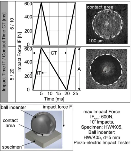
Characteristic experimental results obtained by means of the pie-zoelectric impact tester described in the previous section are demon-strated in Fig. 5. In these two experimental cases, the signal duration of the applied force i.e. the contact time between the ball indenter and the specimen surface is constant. It can be observed in the photos at the right part of Fig. 5, that if the impact time and force amplitude remain constant, the increase of the contact time CT for instance from 10 ms up to 20 ms does not influence the impression diameter. These results show that the surface deformation in the contact area between the ball indenter and the specimen (see Fig. 1) is affected only by the impact
time and force amplitude and therefore the developed stress, strain and strain-rate fields as well. Hence, the force signal duration in the con-ducted experiments was maintained constant equal to 20 ms, for shortening the experiment duration. This contact time corresponds to an impact repetition frequency of 50 Hz.
3.1.2. Surface deformation at constant impact force amplitude and various impact times
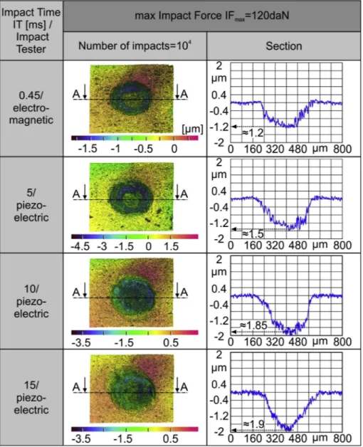
At the applied experimental conditions, a permanent plastic de-formation develops on the cemented carbide insert surfaces at impact force amplitudes larger than approximately 20 daN. The geometry of the formed crater can be captured, and its depth measured (residual imprint depth RID) by means of confocal microscopy. Such impact test results at constant impact force amplitude of 120 daN and various impact times are demonstrated in Fig. 6. The progressive enlargement of the contact crater dimensions, i.e. diameter and RID as the impact time increases can be observed in the related graphs of this figure.
The measured RIDs in the sections of the craters shown in Fig. 6 versus the impact time are illustrated in the diagram of Fig. 7. The used impact testers to create the various imprints are also indicated in this figure. RID increases, as the impact time grows at constant force am-plitude. This tendency can be explained by material strengthening ef-fects at high frequency excitation, i.e. at a shorter impact time [10–12].
3.1.3. Surface deformation at various impact force amplitudes and impact times
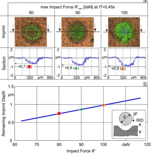
Employing the same experimental and evaluation methods of re-sults, it was possible to record the RIDs after the impact test at various impact times and impact force amplitudes. Such characteristic results are illustrated in Fig. 8. The measured imprint depths, shown in Fig. 8a, are presented versus the impact force in the diagram of Fig. 8b. An almost linear increase of the remaining imprint depth versus the impact force can be observed in this diagram.
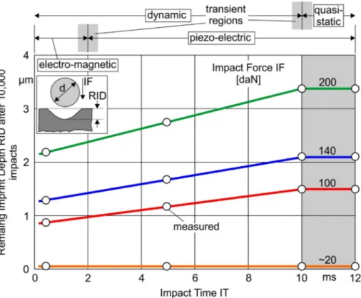
Related investigations were performed at further impact times and forces to determine their effect on the remaining imprint depth for a wider value range. The obtained results are illustrated in the diagrams of Figs. 9 and 10. The diagram of Fig. 9 validates the described ten-dency in Fig. 7 that in the demonstrated cemented carbide case, at impact times longer than 10 ms, the surface response resembles that one of a quasi-static loading. Moreover, Fig. 10 illustrates the almost linear RID growth versus the impact force in a wide range of impact times from 0.45 ms up to longer than 10 ms. For the analytical de-scription of these results associated with ITs shorter than 10 ms, stress, strain, strain-rate dependent material laws are required. To enable their
determination, a FEM supported algorithm was developed, which is introduced in the following sections.
3.2. Computation of deformation, stress and strain fields in the ball indenter and specimen developed during the impact test at quasi static loads
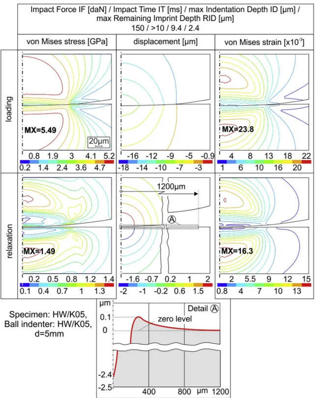
To determine the deformation as well as the equivalent von Mises stress and strain fields in the ball indenter and specimen during the impact test loading and relaxation phases at quasi static loads, the FEM model presented in Fig. 4 was employed. Characteristic results con-cerning these fields at a maximum load of 1500 N are presented in Fig. 11. The results are associated with impact times longer than 10 ms, and according to Fig. 9, they correspond to static loading conditions. In the calculations, the stress-strain data of the cemented carbide shown in Fig. 3c and related to low strain rates were used. According to the de-veloped stress fields during loading, the imposed maximum equivalent stresses in the specimen and indenter are larger than the related yield stress of 3.3 GPa shown in Fig. 3c. Therefore, both the ball indenter and specimen material deform plastically. Since the mechanical properties in the grain boundaries of the cemented carbide are inferior compared to the WC-grain ones, it is reasonable to assume that boundary sliding takes place. It is worth mentioning, that due to the convex indenter geometry, it deforms more than the plane specimen surface. Further-more, the developed residual stress, deformation, and strain fields oc-curring during the relaxation are exhibited in the bottom part of Fig. 11. The remaining deformation of the specimen surface during the relaxa-tion phase is depicted in detail A. It can be observed that a material Fig. 7. Remaining imprint depth versus the impact time at constant impact force. Results obtained using various impact testers.
elevation around the crater vicinity develops, which compensates the specimen volume shrinkage in the compressed crater area. The main stress components of the equivalent von Mises residual stresses at in-dividual regions of the deformed specimen material are introduced in the next figure. Note that the calculated remaining imprint depth RID of approximately of 2.4 μm is practically identical to the measured ones for impact times larger than 10 ms as shown in Fig. 10. The maximum residual strain during loading and the related impact time are con-sidered to calculate the corresponding strain rate, as described in the following sections.
The residual von Mises stress in every elementary region of the deformed material structure during the relaxation phase has two main stress components σ1 and σ2 perpendicular to each other, as presented
in Fig. 12. Due to the axis-symmetrical FEM model, the main stress component σ3 normal to the σ1-σ2 plane is negligible. The σ1 and σ2
stress fields are illustrated in the diagrams of Fig. 12 left and middle respectively. Positive main stress values impose tensile tension in the material structure and negative ones compressive. The dotted lines in the previous diagrams of Fig. 12 are the borders between material re-gions with tensile and compressive stress state. Hereupon, four stress states develop in the material structure during the relaxation, according to the σ1 and σ2 value combinations. These are illustrated in the right
diagram of Fig. 12. If in an elementary region, both main stresses σ1 and
σ2 are negative (case -/- ), the related material is compressively loaded.
In contrast, if both σ1 and σ2 stresses are positive (case +/+), the
material is subjected to tensile tension. In the transient stress cases -/+ and +/- , an elementary material volume is differently loaded in the directions of the main stresses and according to the main stress values. The von Mises equivalent stress at a considered elementary material volume is determined based on the relevant σ1, σ2 and σ3 main stresses.
Fig. 13a demonstrates the course of the impact force versus the imprint depth and the calculated maximum imprint depths (ID) and related RIDs at various impact forces. These results describe accurately the experimental ones presented in Fig. 10 for impact times longer than 10 ms. Moreover, Fig. 13b illustrates the course of the maximum strain versus the imprint depth, in the present case for impact times equal or larger than 10 ms. Combining Fig. 13a and b, the strain rate at an imprint depth can be associated with a certain impact force. Con-sidering the linear growth of the impact force versus the impact time (see Fig. 2b), the corresponding time course of the strain can be de-termined, and thus, the related strain rate as well. Hereupon, for rea-sons of simplification, the strain time course is approximately con-sidered linear. Such calculations are conducted within the algorithm introduced in the next section, for describing the effect of strain rate on the constitutive law of the specimen material.
Fig. 9. Remaining imprint depth RID versus the impact time IT at various impact force IF.
3.3. The developed algorithm to determine the effect of strain rate on the stress-strain curve of cemented carbide materials
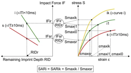
To analytically determine the effect of the impact time and strain rate, on the constitutive material law of the applied cemented carbide material, a convenient FEM supported algorithm was developed as in-troduced in Fig. 14. This algorithm is based on calculations conducted through the FEM simulation of the impact test (itFEMs) as presented in the previous figures, and the experimental results described in Figs. 9 and 10. Firstly, considering the dependence between impact force IF and RID at various ITs (see Fig. 10), the impact force IFsr at impact durations longer than 10 ms and corresponding to a reference RIDr is predicted. IFsr represents a static load. For this impact force, the maximum equivalent strain εmaxsr developed in the cemented carbide substrate during the impact test is calculated via the impact test FEM simulation (itFEMs), as illustrated in Fig. 14b. Hereupon, the applied substrate stress-strain curve s, exhibited in the diagram of Fig. 14b and associated with static loads is employed. The determined strain εmaxsr is constant for the same reference RIDr at every IT shorter or longer than 10 ms. Furthermore, the IFir required to achieve the RIDr is de-fined by using curve “i” shown in the diagram of Fig. 14a describing the impact force versus the remaining imprint depth in the case of impact time ITi shorter than 10 ms (see also Fig. 10). Based on curve “i”, IFir is larger compared to IFsr. In this way, the impact force IFir leads to a larger strain εmaxi0 compared to εmaxsr, if the stress-strain curve s is employed in the calculations using itFEMs. To approximate the εmaxsr at the ITi, the stress-strain curve s of the cemented carbide is displaced proportionally by a stress increase ratio SARi0 equal to Smaxi0/Smaxsr (see curve i1 in the diagram of Fig. 14b). If based on the curve i1, the determined εmaxi1 via the itFEMs is still larger than εmaxsr, the curve i1 is displaced considering an increase ratio SARi1 equal to Smaxi1/
Smaxsr. This procedure is repeated in k successive steps using the it-FEMs, until a εmaxik is obtained deviating from εmaxsr by less than a predefined percentage. Subsequently, the attained stress-strain curve ik, displaced proportionally by the stress increase ratio SARi regarding that one at ITs longer than 10 ms, describes the substrate material stress- strain law at the ITi shorter than 10 ms.
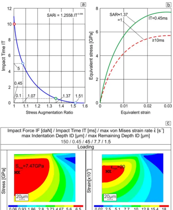
The effect of the impact time ITi on the stress increase ratio SARi can be detected, by repeating the above described steps of the introduced algorithm, as presented in Fig. 15a. The parameter SARi increases ex-ponentially when the impact time ITi diminishes. This relation is de-scribed by the equation demonstrated in this figure. According to these results, an impact time ITi of 0.45 ms corresponds to a SARi approxi-mately equal to 1.37. By employing this value, the stress-strain curve for a K05 cemented carbide material at an impact time ITi equal to 0.45 ms can be determined as depicted in Fig. 15b. For comparison reasons, the corresponding stress-strain law at ITs larger than 10 ms is also illustrated in this figure. Considering these data, the maximum stress and strain fields during the loading phase of an impact test at an impact force of 1500 N and ITi equal to 0.45 ms were predicted using the described itFEMs software. The attained results are illustrated in Fig. 15c. Due to material hardening effects, the developed maximum stress is larger, and the strain smaller compared to the corresponding ones at ITs longer than 10 ms (see Fig. 11). Furthermore, considering the determined maximum strain εmaxi, in the present case equal to 20 × 10−3, related to the impact time ITi of 0.45 ms, as presented in
Fig. 15c , the corresponding strain rate of approximately 45 s−1 is
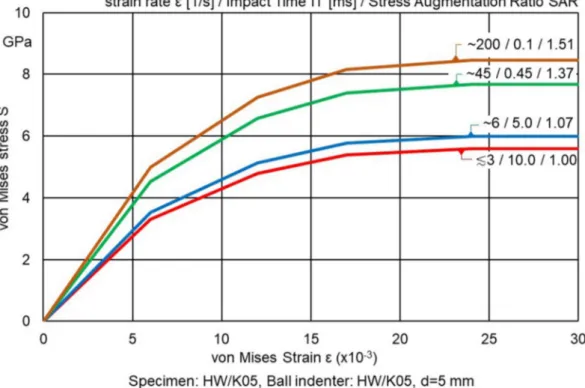
calculated, as perciously explained in section 3.2. In this way, the stress-strain curves can be associated with the relevant strain rates too. By employing the introduced algorithm in Fig. 14, stress, strain, strain-rate dependent constitutive flow curves were determined for the investigated cemented carbide K05, as presented in Fig. 16. The applied Fig. 12. Developed main stress fields in the specimen during the relaxation impact test phase.
stress increase ratios SARi in the algorithm, for every strain rate and impact time case are also monitored. Considering these results, the relation between the impact time IT and strain rate can be analytically described by means of the equation:
=
IT 33.3465 1.0965 (1)
Inserting this equation into the following one:
= i
SAR 1.2558 IT 0.096 (2)
already demonstrated in Fig. 15a, the subsequent relation occurs:
= i
SAR 0.8968 0.1053 (3)
By employing this relation, the SAR can be determined depended on the strain rate . Since SAR is defined as:
=
i i i
SAR Sdynamic/Sstatic (4)
the dynamic materials flow stress Sidynamic can be calculated using
the following equation:
= =
i i
Sdynamic 0.8968 Sstatic 0.1053 K m (5)
Hence, Sidynamic is a function of a material constant K, the strain-rate
, and strain rate sensitivity factor m [13]. The sensitivity factor m equal to 0.1053 falls in the range of 0.02–0.2 of most metals, given in reference [13].
Noteworthy for the case of loading at a stain rate of 200 s−1, is the
dynamic von Mises flow stress increase of the tested cemented carbide material amounting to 51% compared to the corresponding static stress. Consequently, when decreasing the impact time at constant load, the developed stresses increase. Hereupon, at these dynamic strain-rates, inertial effects start changing the homogeneous stress-state in quasi- static loading cases. In this way, movements of dislocations are blocked and regions with stress concentrations occur, thus deteriorating the material ductility and increasing the brittleness. Similar results were presented for ultrahigh-strength steels at strain rates up to 200 s−1 in
reference [14].
Using the itFEMs software and the presented in the previous figure, stress, strain laws for the cemented carbide K05 at various impact times, the experimentally determined dependency between the re-maining imprint depth RID and the impact force IF at different impact times ITs (see Fig. 10) were also analytically defined. The obtained results are illustrated in Fig. 17, where the calculated and experimental results are in good agreement. The calculated RIDs for various ITs de-scribe accurately the experimentally reproduced courses of the impact force versus the remaining imprint depth at the corresponding impact times. Consequently, the presented Eqs. (1) to (5) can be also applied in
determining the dynamic cemented carbide tool deformations in var-ious manufacturing procedures. It must be noted that Eqs. (1) to (5) can be applied up to cutting temperatures of about 500o C, since the
strength properties of K05 cemented carbide are almost invariant up to that temperature [15]. For simulating the impact of few ms time on the coated cutting edge during its entry into the workpiece material in interrupted cutting processes like milling, substrate strength properties at strain rates up to around 200 s−1 are required, such as the introduced
ones in the present paper [16]. In milling at undeformed chip lengths of few decades of mm, which correspond to contact durations of several ms according to the part material and commonly applied cutting speed, the developed maximum cutting temperature on the coated tool rake commonly remains under 500o C [16,17].
4. Conclusions
Stress, strain, strain-rate dependent properties of cemented carbide material were previously not attainable. In the present paper, such data were determined via a FEM-supported evaluation of impact test im-prints on cemented carbide inserts at various impact times and loads. The measured imprint depths, among other parameters, were con-sidered in a developed FEM supported algorithm, which enabled the definition of stress, strain, strain-rate data of the applied cemented carbide material. Based on these properties, the stress and strain fields developed during the impact test at various impact forces and times were determined and the measured remaining imprint depths analyti-cally described with precision. Hence, the accurate calculation of dy-namic deformations of cemented carbide tools during milling and fur-ther relevant manufacturing procedures with interrupted cutting kinematics is facilitated.
Fig. 14. Algorithm for determining stress, strain curves at various impact times considering measured RIDs at different impact forces IFs and times ITs using a FEM simulation of the impact test (itFEMs).
Fig. 15. (a): Dependence between stress increase ratio and impact time. (b): Stress-strain curves at various impact time. (c): Calculated maximum stress and strain fields at the impact time of 0.45 ms.
Author statement
As corresponding author, I Prof. K.-D. Bouzakis, hereby state on behalf of all authors that the paper is original and unpublished and is not being considered for publication elsewhere.
Declaration of Competing Interest
The authors have no conflict of interest to declare. References
[1] K.-D. Bouzakis, N. Michailidis, S. Hadjiyiannis, G. Skordaris, G. Erkens, The effect of specimen roughness and indenter tip geometry on the determination accuracy of thin hard coatings stress–strain laws by nanoindentation, Mater. Charact. 49 (2) (2002) 149–156.
[2] K.-D. Bouzakis, N. Michailidis, Deviations in determining coatings’ and other ma-terials’ mechanical properties, when considering different indenter tip geometries and calibration procedures, Surf. Coat. Technol. 202 (2007) 1108–1112. [3] G. Skordaris, A. Bouzakis, K.-D. Bouzakis, Impact test applications supported by
FEA-models in surface engineering for coatings characterization, Mater. Proc. 2 (2020), https://doi.org/10.3390/CIWC2020-06809.
[4] K.-D. Bouzakis, G. Maliaris, S. Makrimallakis, Strain rate effect on the fatigue failure of thin PVD coatings: an investigation by a novel impact tester with adjustable repetitive force, Int. J. Fatigue 44 (2012) 89–97.
[5] H. Ortner, H. Kolaska, P. Ettmayer, The history of the technological progress of hardmetals, Int. J. Refract. Met. Hard Mater. 44 (2014) 148–159.
[6] J. García, V.-C. Ciprés, A. Blomqvist, B. Kaplan, Cemented carbide microstructures: a review, Int. J. Refract. Met. Hard Mater. 80 (2019) 40–68.
[7] A. Bouzakis, G. Skordaris, K.-D. Bouzakis, M.-G. Gökcen, A. Boumpakis, A.- U. Batuk, S. Sisman, S.-A. Serbes, Determination of Strain Rate Depended Stress and
Strain Fields in PVD Coatings on Cemented Carbide Inserts during the Repetitive Impact Test. Accepted for Publication in Key Engineering Materials, (2020).
[8] Swanson Analysis System, ANSYS User Manuals, Vol. 1Theory, Vol. 2 Procedures,
Vol. 3 Elements, Vol. 4 Commands, INC, 1995.
[9] J.L. Loubet, J.M. Georges, G. Meille, Vickers Indentation Curves of Elastoplastic Materials, Micro indentation Techniques in Material Science and Engineering.
ASTM STP 889, Philadelphia, (1986), pp. 72–89.
[10] L.E. Murr, Metallurgical Effects of Shock and High-Strain-Rate Loading., Blazynski TZ, Editor, Materials at High Strain Rates, Elsevier, Essex (England), 1987, pp. 1–46.
[11] J. Harding, The Effect of High Strain Rates on Material Properties, Blazynski TZ, Editor, Materials at High Strain Rates, Elsevier, Essex (England), 1987, pp. 133–186.
[12] L.W. Meyer, Material Behaviour at High Strain Rates, 1st International Conference on High Speed Forming, (2004), pp. 45–56, https://doi.org/10.17877/DE290R- 12976.
[13] R.W. Herzberg, Deformation and Fracture Mechanics of Engineering Materials, 3rd
Ed, John Wiley & Sons, New York, 1989.
[14] B.L. Boyce, M.F. Dilmore, The dynamic tensile behavior of tough, ultra-high
strength steels at strain-rates from 0.0002 s_1 to 200 s_1, Int. J. Imp. Eng. 36 (2) (2009) 263–271.
[15] K.-D. Bouzakis, M. Batsiolas, G. Skordaris, F. Stergioudi, N. Michailidis, Repetitive impact test near uncoated and coated cutting edges for assessing their fatigue be-havior, CIRP J. Manuf. Sci. Technol. 8 (2015) 63–69.
[16] K.-D. Bouzakis, S. Makrimallakis, G. Skordaris, E. Bouzakis, S. Kombogiannis, G. Katirtzoglou, G. Maliaris, Coated tools’ performance in up and down milling stainless steel, explained by film mechanical and fatigue properties, Wear 303 (1–2) (2013) 546–559.
[17] K.-D. Bouzakis, E. Bouzakis, S. Kombogiannis, S. Makrimallakis, G. Skordaris, N. Michailidis, P. Charalampous, R. Paraskevopoulou, R. M’Saoubi, J.C. Aurich, F. Barthelmä, D. Biermann, B. Denkena, D. Dimitrov, S. Engin, B. Karpuschewski, F. Klocke, T. Özel, G. Poulachonm, J. Rech, V. Schulze, L. Settineri, A. Srivastava, K. Wegener, E. Uhlmann, P. Zeman, Effect of cutting edge preparation of coated tools on their performance in milling various materials, CIRP J. Manuf. Sci. Technol. 7 (2014) 264–273.