Negative refraction and subwavelength focusing using left-handed
composite metamaterials
Ekmel Ozbay
*and Koray Aydin
Nanotechnology Research Center, Department of Physics, and Department of Electrical and Electronics Engineering, Bilkent University, Bilkent, 06800 Ankara, Turkey
ABSTRACT
We review experimental studies performed on left-handed metamaterials (LHM) at microwave frequencies. The metamaterial structure is composed of periodic arrays of split-ring resonators and wire meshes and exhibits a left-handed propagation band at frequencies of negative permittivity and negative permeability. Negative refraction is verified using prism shaped LHM and also by beam-shifting method. Subwavelength focusing of a point source is achieved with a resolution of 0.13λ through a flat LHM superlens.
Keywords: metamaterials, left-handed metamaterial, negative refractive index, superlens.
1 INTRODUCTION
In recent years, there has been a burgeoning interest in rapidly growing field of metamaterials due to their unprecedented properties unattainable from ordinary materials. Veselago pointed out that a material exhibiting negative values of dielectric permittivity (ε) and magnetic permeability (µ) would have a negative refractive index [1]. Generally speaking, the dielectric permittivity (ε) and the magnetic permeability (µ) are both positive for natural materials. In fact, it is possible to obtain negative values for ε and µ by utilizing proper designs of metamaterials. Left-handed electromagnetism and negative refraction are achievable with artificially structured metamaterials exhibiting negative values of permittivity and permeability simultaneously at a certain frequency region. The first steps to realize these novel type of materials were taken by Smith et al., where they were able to observe a left-handed propagation band at frequencies where both dielectric permittivity and magnetic permeability of the composite metamaterial are negative [2]. Soon after, left-handed metamaterials with an effective negative index of refraction are successfully demonstrated by various groups [3].
A perfect lens is one of the most important applications of materials with a negative refractive index. The term, perfect lens, was coined by J. B. Pendry owing to the ability of such lenses to reconstruct a perfect image by recovering the evanescent components of EM waves [4]. Ordinary materials with a positive refractive index always require curved surfaces to focus EM waves. Positive-index lenses suffer from the diffraction limit that is dictated by wave optics and can only focus objects with sizes on the order of a half-wavelength. The finer details of the image are carried by high-k components, the so called evanescent waves and quickly decay before reaching the image plane. Therefore, the contribution of evanescent components to the resolution of the image is absent in conventional lenses. Negative index materials can restore the amplitude of evanescent waves and therefore enable subwavelength focusing [5].
In this paper, we review our experimental studies on left-handed metamaterials by studying their transmission, reflection, refraction and focusing characteristics. The negative index of refraction for the two-dimensional (2D) LHM is verified by measuring the refraction from a prism-shaped LHM structure. An alternative method, phase-shift measurements are employed to check the validity of the refraction measurements. Point source is imaged with a resolution of 0.13λ by using a thin (3 layer) LHM based superlens. Moreover, we have been able to resolve two closely placed point sources that are λ/8 apart. The measurements reveal the possibility of subwavelength imaging and resolution from left-handed metamaterial superlenses at microwave frequencies.
— SRR
— LHM
3.5 4.0 4.5 5.0 Frequency (GHz) 3.4 3.6 3.8 4.0 4.2 4.4 4.6 Frequency (GHz)2 TRANSMISSION THROUGH LEFT-HANDED METAMATERIALS
The left-handed metamaterial under investigation is composed of periodic arrangement of split-ring resonators (SRRs) and thin wire grids [5]. Periodic thin wire media is responsible for the negative effective permittivity, whereas periodic SRR structure provides negative effective permeability. The LHM studied in this work consists of the two-dimensional periodic arrangement of split-ring resonator (SRR) and thin wire arrays. The parameters of the 2D LHM structure could be found elsewhere [6].
Fig. 1. Measured transmission spectra of periodic SRR (blue line) and LHM (red line) arrays.
To obtain negative permeability, we periodically arranged SRR structures. Experimental setup for measuring the transmission-amplitude and transmission-phase spectra consists of a HP 8510C network analyzer, and standard high gain microwave horn antennas. Figure 1 shows the measured transmission spectrum of periodic SRRs. We observed a band gap between 3.55-4.05 GHz [5]. This band gap is caused by negative values magnetic permeability. We combined SRRs and wires together in a two-dimensional arrangement [6]. The plasma frequency of the wire array that is used to construct the left-handed material in this study is shown to be at 8.0 GHz in a previous study [5]. Therefore below 8.0 GHz, the effective permittivity of wire array is negative. Therefore, one should observe a transmission band within the frequency region where both permittivity and permeability are negative. As seen in Fig.1, a transmission band is observed between 3.65−4.05 GHz, where the effective permeability and effective permittivity of LHM are simultaneously negative. The peak value within this transmission band is -7.6 dB at 3.86 GHz. The structure has 3 unit cells along the propagation direction.
3.5 3.0 2.5 2.0 1.5 1.0 0.5 0.0 -0.5 3.3 3.4 3.5 3.6 3.7 3.8 3.9 4.0 4.1 Frequency (GHz) 0 -5 m
-i
-10 c, 0 -15 a w -20 Frequency (GHz)We also performed reflection measurements where the results are plotted in Fig. 2 together with the transmission spectrum. We observed a dip in the reflection spectra at 3.78 GHz. The reflection is very low around -35 dB meaning that the incident EM waves do not face significant amount of reflection at the LHM surface. The low reflection from the surface can be attributed to either matched impedance at the interface or to the thickness resonance of the slab. In the following section, we have shown by extracting the effective parameters using retrieval procedure, that the impedance is matched to the free space. Impedance matching is desired for NIM structures, since it is required to achieve a perfect lens.
3 EFFECTIVE PARAMETERS AND IMPEDANCE MATCHING
The effective parameters of the NIM are retrieved by using the calculated amplitudes and phases of transmission and reflection. Dielectric permittivity,
ε
=
ε
'
+
i
ε
"
and magnetic permeability,µ
=
µ
'
+
i
µ
"
are used to describe the response of materials to the incident electromagnetic field; whereε
'
andµ
'
are the real parts,"
ε
andµ
"
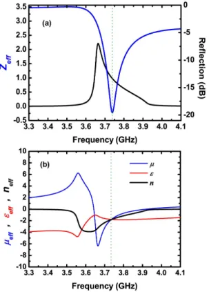
are the imaginary parts of the corresponding effective parameters. Figure 3(a) depicts the real part of impedance (blue line) and calculated reflection coefficient (black line). The minimum reflection in the simulations occurs at 3.74 GHz, where Z=1. In Fig. 3(b) we plotted the real parts ofµ
(blue line)ε
(red line) and, and refractive index (black line).ε
'
andµ
'
possesses negative values between 3.63−3.93 GHz. At the lowest reflectionε
'
=µ
'
= -1.8 (dashed green line). The impedance is defined asZ
=
µ
'
/
ε
'
, therefore impedance matching is obtained when'
ε
=µ
'
. Expectedly, the impedance of NIM is matched to that of free-space at 3.74 GHz, where Z’=1.Fig. 3. Retrieved effective parameters of 2D LHM. (a) Real parts of permeability, permittivitiy and refractive index and (b) reflection spectrum and real part of impedance.
3.85 3.80
-60 -40
-20Refraction Angle (°)
4 EXPERIMENTAL VERIFICATION OF NEGATIVE REFRACTION
Although transmission measurements provide some information about the composite metamaterial of SRRs and wires, additional measurements must be done in order to assure that the metamaterial has left-handed characteristics. For this purpose, we performed experiments to verify the refractive index of the 2D LHM under investigation is indeed negative. Prism-shaped structures can be used to find the sign and the value of the refractive index [3,6]. We constructed a prism-shaped LHM with a prism angle of θ = 26°. The first interface of left-handed material is excited with EM waves emanating from the transmitter horn antenna located at a distance of 13 cm (~2λ) away from the first interface of the prism. The receiver horn antenna is placed 70 cm (~10λ) away from the second interface of the sample and mounted on a rotating arm to scan the angular distribution of the refracted signal. Details of the experiments could be found in ref. 6.
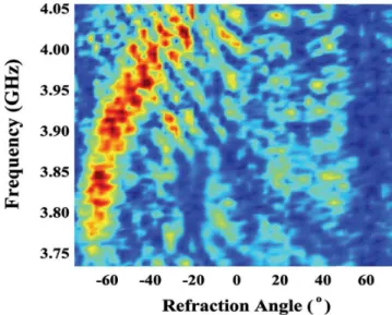
Fig. 4. Measured beam profiles of the EM waves refracted from a 2D prism shaped LHM as a function of frequency and angle of refraction between 3.73 - 4.05 GHz. The beam clearly refracted on the negative side of the normal, indicating a negative refraction behavior.
The measured field intensity at 70 cm away from the prism is plotted as a function of frequency and refraction angle in Fig. 4. It is evident from the figure that the transmitted beam is refracted on the negative side of the normal, so that the refraction angle is negative. Negative refraction angle could only be possible if the measured sample has a negative refractive index. This is easily deducible from the Snell’s law which in our case could be written as nLHMsinθi =
nair sinθr. This measurement verifies that the refractive index values of the 2D LHM is negative between 3.73 and 4.05 GHz. At lower frequencies the EM waves are refracted at higher negative refraction angles, which results in a higher negative refractive index. The refraction index is lowered if we go to higher frequencies. The angle of the refraction at 3.86 GHz is measured to be θr = -60°. By using Snell’s law, the refractive index is calculated as neff = -1.91 ± 0.05 at 3.86 GHz, where the maximum transmission is observed.
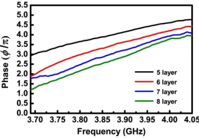
For materials with a negative refractive index, the phase velocity and energy flow are anti-parallel inside a LHM. Therefore the phase velocity points toward the source. We developed a method to observe the phase shift by measuring the transmission phases for LHMs with varying thicknesses and verified that the phase velocity is negative [6]. We have constructed 4 different 2D LHM slabs with number of layers Nz = 5, 6, 7 and 8. The transmitted phases are plotted in the frequency range 3.65-4.00 GHz, which is within the left-handed transmission region.
Figure 5 shows the transmitted phase for different number of layers of LHM slabs. It is evident from the figure that, increasing the number of layers of LHM results in a decrease at the phase of the transmitted EM wave. However, if the material possesses a positive refractive index, one would observe an increase in the transmitted phase with the increasing number of unit cells [6].
5.5 5.0 4.5 4.0
w 2.5
U, 2.0 1.0 0.5 0.03.70 3.75 3.80 3.85 3.90 3.95 4.00 4.05
Frequency (GHz)
Fig. 5. The measured transmission phase spectra of LHMs with 5, 6, 7 and 8 number of layers along the propagation direction.
The index of refraction in terms of wavelength, phase shift, and change in the length of left-handed material is given by:
π
λ
φ
2
L
n
∆
∆
=
(1)At f=3.86 GHz, the wavelength of the EM wave is λ=7.77 cm. The average phase shift per unit cell (∆L=8.8 mm) obtained from the experimental results is ∆Φ = -0.45±0.04π. Inserting these values in (1), index of refraction at 3.86 GHz is found to be neff = -1.98±0.18. The average phase shift and calculated refractive index for the numerical simulations at 3.77 GHz are ∆Φ = -0.51±0.04π, and neff = -2.31±0.18.
5 SUBWAVELENGTH RESOLUTION
In the previous section, we confirmed that the metamaterial structure has a left-handed propagation band and possesses negative values of refractive index. In his paper, Pendry conceived that a negative index material could be a potential candidate for imaging beyond the diffraction limit [4]. Here, we employ the LHM under investigation in imaging measurement. The imaging measurements are performed at 3.78 GHz, where the reflection is considerably low and the losses due to reflection are negligible. The impedance is matched at 3.78 GHz for perpendicular normal incidence, however the reflection will still affect the performance of LHM superlens for oblique incidence.
In the imaging experiments, we used monopole antennae to imitate the point source. The exposed center conductor acts as the transmitter and receiver and has a length of 4 cm (~λ/2). Firstly, we measured the beam profile in free space that is plotted in Fig. 6 with a red dashed line. The full width at half maximum (FWHM) of the beam is 8.2 cm (1.03λ). Then, we inserted LHM superlens, and measured the spot size of the beam as 0.13λ, which is well below the diffraction limit (black line) [7]. The LHM superlens has 40×20×3 layers along the x, y, and z directions. The source is located ds=1.2 cm away from first boundary and the image forms di=0.8 cm away from second boundary of the superlens. The intensity of the electric field at the image plane is scanned by the receiver monopole antenna with ∆x = 2 mm steps.
1.0 • •
0.9 — superlens
0.8 —-—air 0.7 0.6 0.5 0.4 0.3 0.2 0.1 . 0.0-8 -7 -6 -5 -4 -3 -2 -1 0 1 2 3 4 5 6 7 8
Lateral Position (cm)I.O.U U
U U U I UI I U
I U U I U: ii
-8 -7 -6 -5 -4 -3 -2 -1 0 1 2 3 4 5 6 7 8 Lateral Position (cm)Fig. 6. The measured power distributions at the image plane with 3 layer (black line) and 5 layer (red line) LHM superlenses. Blue dashed line corresponds to the power distribution in free space. Normalized intensity in free space is multiplied with 0.2.
Since we were able to image a single point source with a subwavelength spot size, we used two point sources separated by distances smaller than a wavelength to obtain subwavelength resolution. The sources are driven by two independent signal generators and the power distribution is detected by using a microwave spectrum analyzer. The frequencies of the sources differ by 1 MHz to ensure that the sources are entirely incoherent. The imaging experiments are performed for two different separation distances between the sources. The measured power distribution of sources, separated by λ/8, is plotted by the blue line in Fig. 7. As seen in the figure, the peaks of two sources are resolved. We then increased the separation of the sources to a distance of λ/5 (red line) and the peaks are resolved better. When the sources are λ/3 apart (green line), we have been able to resolve two peaks entirely.
Fig. 7. The measured power distributions for two point sources separated with distances of λ/8 (blue line), λ/5 (red line) and λ/3 (green line).
In order to avoid any possible channeling effects, the sources are intentionally not placed at the line of SRR-wire boards. Besides, the distances between the sources in the experiments are carefully chosen such that they are not
indeed the LHM structure behaves as an effective medium. The periodicity has a significant effect on the resolution of the superlens by limiting the recovery of evanescent components. The resolving power can be further increased by using structures with smaller periodicities, but we are restricted to a periodicity of 9.3 mm in order to fabricate an effective 2D LHM.
In the near-field regime, the electrostatic and magnetostatic limits apply, and therefore, the electric and magnetic responses of materials can be treated as decoupled [23]. This in turn brings the possibility of constructing superlenses from materials with negative permittivity or negative permeability. The advantage of using negative-index lenses over negative-permittivity or negative-permeability lenses is that the subwavelength resolution can be obtained for both transverse-electric (TE) and transverse-magnetic (TM) polarization of EM waves. However, single-negative lenses can only focus EM waves with one particular polarization.
6 CONCLUSION
We studied transmission, refraction and imaging of a two-dimensional left-handed metamaterial experimentally. We observed a band gap at the transmission spectrum of SRR array which is due to the negative magnetic permeability. A left-handed transmission band is obtained when a wire array is added at the back side of SRR array. The transmission band appeared at a frequency regime where both the effective dielectric permittivity and magnetic permeability of the LHM are simultaneously negative. By measuring the refraction through a prism-shaped LHM, we verified that the structure has a negative refractive index. Subwavelength imaging measurements are performed by using monopole antennae as point sources. The superlens behavior of a 2D LHM slab is verified. The resolution of the superlens is shown to be 0.13λ.
ACKNOWLEDGMENT
This work is supported by the European Union under the projects METAMORPHOSE, EU-NoE-PHOREMOST, and TUBITAK under Projects Nos. 104E090, 105E066, 105A005, and 106A017. One of the authors (E.O.) also acknowledges partial support from the Turkish Academy of Sciences.
References
[1] V. G. Veselago, “The electrodynamics of substances with simultaneously negative values of permittivity and permeability,” Sov. Phys. Usp. 10, 509 (1968).
[2] D. R. Smith, W. J. Padilla, D. C. Vier, S. C. Nemat-Nasser, and S. Schultz, “Composite medium with simultaneously negative permeability and permittivity,” Phys. Rev. Lett. 84, 4184-4187 (2000) [doi:10.1103/PhysRevLett.84.4184].
[3] R. A. Shelby, D. R. Smith, and S. Schultz, “Experimental verification of a negative index of refraction,” Science 292, 77-79 (2001) [doi:10.1126/science.1058847].
[4] J. B. Pendry, “Negative refraction makes a perfect lens,” Phys. Rev. Lett. 85, 3966-3969 (2000) [doi:10.1103/PhysRevLett.85.3966].
[5] K. Aydin, K. Guven, C. M. Soukoulis, and E. Ozbay, “Observation of negative refraction and negative phase velocity in left-handed metamaterials,” Appl. Phys. Lett. 86, 124102 (2005) [doi:10.1063/1.1888051].
[6] K. Aydin, K. Guven, M. Kafesaki, L. Zhang, C. M. Soukoulis, and E. Ozbay, “Experimental observation of true left-handed transmission peak in metamaterials,” Opt. Lett. 29, 2623-2625 (2004) [doi:10.1364/OL.29.002623]. [7] K. Aydin, I. Bulu, and E. Ozbay, “Subwavelength resolution with a negative-index metamaterial superlens” Appl.