FINAL STRUCTURE & DESIGN PARAMETERS OF TARLA RF SYSTEM*
O. Karsli
#, C. Polat, C. Kaya, A. Aksoy, B.Koc, O. Yavas, IAT, Ankara Univ., Ankara, Turkey
M. Dogan, Dogus Univ., Istanbul, Turkey
S. Ozkorucuklu, Istanbul Univ., Istanbul, Turkey
Abstract
Turkish Accelerator and Radiation Laboratory in Ankara (TARLA) is an oscillator mode IR-FEL facility which is under construction since 2011. ELBE licensed superconducting modules housing TESLA RF cavities have been manufacturing for one year and the first module will be delivered in 2015. He Cryogenic System has also started to be manufacturing at similar time with the accelerator structures. It will be delivered in 2014. High Power RF amplifiers are started to tender procedures and delivery time is planning as 2015. The installation of high power transmission lines have to be completed at the same time with the delivery date of HPRF amplifiers to test the cavities and amplifiers. In this study, the final structural design of high power RF transmission lines and design parameters of RF amplifiers for TARLA is discussed.
INTRODUCTION
TARLA will include a thermionic electron source; two ELBE designed superconducting electron accelerator modules housing four TESLA RF cavities with operating frequency of 1.3 GHz, and two optical cavity system including two different undulator magnets with periods of 25 mm (U25) and 90 mm (U90) [1].
The accelerated electron beam with the energy of 10-40 MeV from ELBE modules will interact with the undulator magnets by trapping between two mirrors in the optical cavities and produce 3-250 μm oscillator Free Electron Laser (FEL) in infrared region. TARLA will also have Bremsstrahlung radiation at the exit of the second ELBE superconducting accelerator module (linac) [2].
TARLA injector unit by generating the electron beam will pre-accelerate to ~250 keV/m, before sending to the main accelerator section (ELBE modules) at dedicated frequency. The electron beam has been striving to achieve both in continuous and pulsed mode in 2014. The commissioning of electron beam acceleration part of TARLA is planned to be ready in 2015 for performing the electron beam tests.
Thermionic electron source, the first part of the injector, is manufactured in Ankara. The first DC beam was obtained with the energy of 165 keV/m in April 2013. Injector installation and control studies are still in progress to obtain 235 keV/m pulsed electron beam at 1.3 GHz before sending to the superconducting accelerator modules [3].
The injector part will also include two ELBE designed normal conducting RF buncher cavities named sub harmonic and fundamental buncher. Buncher cavities are used to compress 500 ps long electron bunches extracted from electron source to 10 ps in dedicated frequency.
Main acceleration section will consist of two modules, each including a pair of TESLA RF cavities. Each cryomodule will be driven by a pair of 18 kW (saturated) high power solid state RF amplifiers in 1.3 GHz which is around the operation frequency of RF cavities. RF power will be transmitted to the cryomodules by waveguides and fed into the cavities by fixed antenna coupling [4].
The superconducting modules, RF buncher cavities and Helium Cooling System are still under manufacturing. The first superconducting module and RF buncher cavities are planned to be accepted in 2014. The shipment of Helium Cooling System also will be in 2014.
TARLA RF SYSTEM
TARLA high power RF system will have four RF stations to feed four TESLA RF cavities settled in two superconducting modules. RF power from amplifiers will be delivered to cryomodules by WR650 waveguides.
LLRF System Design
Low Level RF system will be designed and configured in 2015. Both the two main control schemes which are Generator Driven Resonator (GDR) and Self Excited Loop (SEL) for LLRF system will be used for fast adaptation. Control algoritms are planned to be implemented on FPGA like digital platforms. Schematic view of TARLA LLRF system has been shown in Fig.1. [5]
High Power RF (HPRF) Amplifiers
The stability and low noise are indispensable requirements around 1.3 GHz. Amplifier parameters are determined according to the electron beam requirements. It has been chosen solid state RF power amplifiers as high power RF sources, since they are more compact and have easier sustainability and longer life time than klystron like structures.
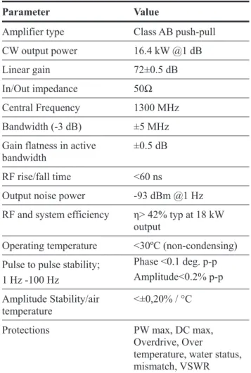
18 kW saturated RF power amplifiers are proposed to obtain 40 MeV beam energy for 1 mA average electron beam current by operating two SRF modules of TARLA. The procurement procedures have been continuing with Sigmaphi Accelerator Technologies (Bruker) since 2014. Table 1 shows the main parameters of TARLA high power RF amplifiers to be procured [6, 7, 8].
_____________________
*Work supported by Turkish Ministry of Development under Grant no: DPT2006K-120470.
#Corresponding author: [email protected]
Proceedings of IPAC2014, Dresden, Germany WEPRI044
07 Accelerator Technology Main Systems T07 Superconducting RF ISBN 978-3-95450-132-8 2577 Copyright © 2014 CC-BY -3.0 and by the respecti v e authors
Figure 1: Schematic view of TARLA LLRF system.
High Power RF Transmission Lines
The RF power transmission into the TESLA RF cavities will be 16 kW by taken into consideration of the amplitude, phase and transmission line losses, e.g. the reflecting power arising from mismatching. TARLA will
have four RF transmission lines connected to four HPRF amplifiers. It has been studied on different types of transfer line system designs [4]. Each general transfer line system for four transmission lines are named as Transmission Line (#).
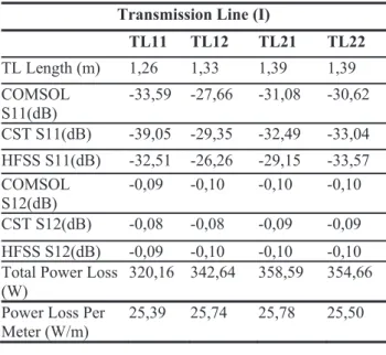
The final RF transmission line was determined among the chosen two of several designs by taking into consideration of optimal transport power losses derived from Comsol Multiphysics, Ansys HFSS & CST simulation results. The last simulated transmission line designs named as Transmission Line (I) and Transmission Line (II) are shown in Fig.2. and Fig.3 respectively [7, 8].
Table 1: High Power RF Amplifier Parameters
Figure 2: Schematic view of high power Transmission Line (I) of TARLA.
Figure 3: Schematic view of high power Transmission Line (II) of TARLA.
Parameter Value
Amplifier type Class AB push-pull
CW output power 16.4 kW @1 dB
Linear gain 72±0.5 dB
In/Out impedance 50
Central Frequency 1300 MHz
Bandwidth (-3 dB) ±5 MHz
Gain flatness in active
bandwidth ±0.5 dB
RF rise/fall time <60 ns
Output noise power -93 dBm @1 Hz
RF and system efficiency Ș> 42% typ at 18 kW
output
Operating temperature <30ºC (non-condensing)
Pulse to pulse stability; 1 Hz -100 Hz Phase <0.1 deg. p-p Amplitude<0.2% p-p Amplitude Stability/air temperature <±0,20% / °C
Protections PW max, DC max,
Overdrive, Over
temperature, water status, mismatch, VSWR
WEPRI044 Proceedings of IPAC2014, Dresden, Germany
ISBN 978-3-95450-132-8 2578 Copyright © 2014 CC-BY -3.0 and by the respecti v e authors
07 Accelerator Technology Main Systems T07 Superconducting RF
The simulation results of Comsol Multiphysics and CST show that the scattering parameters are quite similar while HFSS results are slightly different for Transmission Line (I) and Transmission Line (II) due to high accuracy and included non-negligible parameters by HFSS. Computed power losses are shown in Table 2 and Table 3 respectively for the selected transfer lines.
According to the simulation results and computed power losses, although the power losses of Transmission Line (I) are similar with the Transmission Line (II), Transmission Line (II) has been selected as the final structure of TARLA high power RF transfer line. The total loss per line ~300 W for given incident power which is 16 kW. It means TARLA will have ~%2 power loss per line which is consistent with the literatures and the similar laboratories. The power loss per meter is ~25W for each line as well.
Table 2: S parameters and Computed Power Loss Values of Transmission Line (I)
Transmission Line (I)
TL11 TL12 TL21 TL22 TL Length (m) 1,26 1,33 1,39 1,39 COMSOL S11(dB) -33,59 -27,66 -31,08 -30,62 CST S11(dB) -39,05 -29,35 -32,49 -33,04 HFSS S11(dB) -32,51 -26,26 -29,15 -33,57 COMSOL S12(dB) -0,09 -0,10 -0,10 -0,10 CST S12(dB) -0,08 -0,08 -0,09 -0,09 HFSS S12(dB) -0,09 -0,10 -0,10 -0,10
Total Power Loss
(W) 320,16 342,64 358,59 354,66
Power Loss Per
Meter (W/m) 25,39 25,74 25,78 25,50
CONCLUSION
The installation of TARLA has been continuing since 2011. He Cooling System for superconducting modules will be accepted and made ready for the tests in 2014. Superconducting modules have been manufacturing since 2012 and will be delivered to the first quarter of 2015.
The negotiations of high power RF amplifiers for RF sources to the cavities have been still ongoing. It is expected to have the RF amplifiers in 2015.
Additionally, the component list of RF transfer lines are constituted after the final structure is determined. It will be made contact with the waveguide manufacturers starting to the procurement of the transfer lines.
The installation of the waveguide components and the delivery of high power RF amplifiers have been planning to complete at the same time.
Once high power RF works will be completed, the tests of superconducting modules without beam will be started, according to the LLRF studies.
Table 3: S parameters and Computed Power Loss Values of Transmission Line (II)
ACKNOWLEDGMENT
This manuscript is dedicated to TARLA team who works devotedly to commission for TARLA facility successfully.
REFERENCES
[1] A. Aksoy, O. KarslÕ and O. Yavas, "The Turkish Accelerator Complex IR FEL Facility”, Infrared Physics and Technology 51, (2008) pp.378-381. [2] A. Aksoy et. al., “Design Parameters and Current
Status of The TARLA Project”, IPAC’14, THPR0026, to be published.
[3] C. Kaya et. al., “Beam Diagnostics of E-Gun Test Stand at TARLA”, IPAC’14, MOPRI045, to be published.
[4] O.Karsli and O.Yavas, “A Design Study on High Power RF System for the TARLA Facility of TAC”, Nuclear Instruments and Methods in Physics Research A 693, (2012) pp.215-219.
[5] The installation report on TARLA website: http://tarla.org.tr/
[6] Internal report on HPA with Sigmaphi (Bruker), June 2013.
[7] O. Karsli, et al., “Design of L Band 20 kW High Power Solid State Amplifier for TARLA / TAC Project”, Journal of Higher Education Institution, Ɏ ɂ Ɂ ɂ Ʉ Ⱥ, Tom55, No:10/3, (2013) 154-159.
[8] O. Karsli, “Accelerator RF Wave Production, Transport and Control Systems Design in Particle Accelerators”, PhD Thesis, Ankara University, 2012.
Transmission Line (II)
TL11 TL12 TL21 TL22 TL Length (m) 1,31 1,38 1,44 1,44 COMSOL S11(dB) -32,72 -29,03 -32,48 -30,73 CST S11(dB) -33,80 -30,91 -35,91 -34,48 HFSS S11(dB) -41,35 -27,48 -33,46 -39,03 COMSOL S12(dB) -0,09 -0,10 -0,10 -0,10 CST S12(dB) -0,08 -0,07 -0,09 -0,09 HFSS S12(dB) -0,09 -0,10 -0,10 -0,10
Total Power Loss (W)
326,81 335,90 359,03 359,35 Power Loss Per
Meter (W/m) 24,93 24,32 24,92 24,94
Proceedings of IPAC2014, Dresden, Germany WEPRI044
07 Accelerator Technology Main Systems T07 Superconducting RF ISBN 978-3-95450-132-8 2579 Copyright © 2014 CC-BY -3.0 and by the respecti v e authors