Available bit rate traffic engineering in MPLS networks with flow-based multipath routing
9
0
0
Tam metin
(2) IEICE TRANS. COMMUN., VOL.E87–B, NO.10 OCTOBER 2004. 2914. of network resources. A number of studies propose a centralized optimization algorithm to calculate a set of optimal link metrics to improve routing performance [3]–[5]. Once computed, these link metrics can be reconfigured into the core IP routers either manually or automatically. This approach is effective particularly when the traffic matrix does not change significantly in short time scales [6]. An alternative traffic engineering approach is the overlay approach in which the service providers establish logical connections between the edge nodes of their backbone, and then overlay these logical connections onto the physical topology. The overlay approach replaces the hop-by-hop routing paradigm in traditional IP networks with explicit routing. The emergence of Multi Protocol Label Switching (MPLS) technology provides the necessary protocols and mechanisms in IP backbones for explicit routing to facilitate traffic engineering [2], [7]. In MPLS backbones, one can use a constraint-based routing scheme so that traffic can be controlled to flow optimally through certain routes [8], [9]. Multipath routing is another traffic engineering methodology. The goal of multipath routing is to improve the utilization of resources of an underlying physical network by providing multiple paths between s-d pairs and by dynamically splitting traffic among these paths. Multipath routing concepts were introduced in the context of circuit switched networks and in particular telephone networks, see for example [10] and [11]. Consider a fully connected telephone network with N nodes operating RAR (Random Alternate Routing) in which a new arriving call has a direct primary route and N − 2 two-hop secondary routes [12]. This call will be carried on the primary route if possible, and if not, a route will be selected at random from the set of secondary routes. The call will be lost if no circuits are available on this alternate route. One might be tempted to think that using secondary routes reduces blocking probabilities since this gives each call more opportunities of being accepted to the network. However, if secondary routes are longer in length and they therefore use more resources than the primary routes as in the case of RAR, then the performance of the network in terms of the overall loss probability may be worse than the case of using only direct routes [13]. The reason for this counter-intuitive behavior is that for high loads, alternately routed calls take up twice as many resources compared to directly routed calls and they block directly routed traffic in both links used [12]. This in turn forces one to use alternate routes for this blocked traffic and this cascading effect is referred to as the knock-on effect [14]. One might abandon alternate routing altogether and only use direct routes to cope with this knock-on effect. Such a scheme is analogous to shortest path routing in IP networks. Another well-known approach in alternate routing is a simple priority technique, called trunk reservation, which was first proposed in [13] and shown to significantly improve network performance. In this scheme, a number of circuits on a given link is dedicated for the use of directly routed traffic.. One of the main goals of this paper is to explore a potential counterpart of trunk reservation in IP/MPLS networks. For the current paper, we use a more general definition of the knock-on effect from [15] which refers to the knock-on effect as the phenomenon where using alternative paths by some sources force other sources whose min-hop paths share links with these alternative paths to also use alternative paths. This cascading effect is shown to result in a drastic reduction of the overall resource utilization of the network [15]. This general definition of the knock-on effect also applies to more general data networks and a selfrefrained alternate routing method is proposed to deal with the knock-on effect for QoS routing in [15]. We note that this problem is different than the multipath routing problem for best-effort networks, which is studied in the current paper. Multipath routing research in data networks is relatively new. The work in [16] involves a dynamic multipath routing algorithm in general connection-oriented data networks where the shortest path is used under light traffic conditions and multiple paths are used as the shortest path becomes congested. Recently, there have been a number of multipath traffic engineering proposals for MPLS backbones that are amenable to distributed and online implementation. In [6], probe packets are transmitted periodically to the destination node which then returns them back to the source node. Based on the information in the returning probe packets, the source node computes the one-way congestion statistics which can be delay or loss, and uses a gradient projection algorithm for load balancing. In this model [6], all paths between an s-d pair are treated equally which may be problematic in scenarios for which some paths have longer hop length than the min-hop path. Additive Increase Multiplicative Decrease (AIMD) feedback algorithms are used generally for flow and congestion control in computer and communication networks [17], [18]. The multipath-AIMD approach of [19] uses binary feedback information corresponding to the congestion state of the LSPs and a traffic splitting heuristic using an AIMD rule is proposed that ensures that source nodes never send traffic to secondary paths of longer length before they make full use of their primary paths. Another challenge in multipath routing is that traffic splitting schemes need to avoid or minimize packet reordering, which can significantly deteriorate end-to-end performance [20], [21]. For static traffic splitting in which splitting ratios do not vary over time, hashing-based schemes are shown to be effective in terms of both cost and performance [20]. In dynamic traffic splitting, splitting ratios change adaptively in time with changing congestion status. Flow-based multipath routing schemes are dynamic splitting mechanisms that operate on a per-flow basis with the aim of avoiding packet reordering within a flow; see for example [22] and [23] for related work..
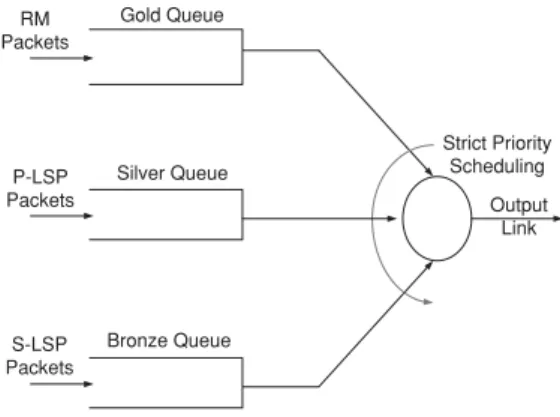
(3) AKAR et al.: AVAILABLE BIT RATE TRAFFIC ENGINEERING. 2915. 3.. Architecture. Our proposed traffic engineering architecture is comprised of the following three components: • Network architecture, • Feedback mechanism, • Flow-based traffic splitting, which are studied next. 3.1 Network Architecture As the network architecture, we propose an MPLS network that supports differentiated services (diffserv) with three Olympic services (gold, silver, and bronze). The gold service is dedicated for the Resource Management (RM) packets used for explicit rate feedback. The silver and bronze services are used by data packets in the way described below. We establish two link-disjoint LSPs between every pair of IP routers, i.e., the paths do not share a common link. For a particular s-d pair, the primary LSP uses the min-hop path found using Dijkstra’s algorithm. When there is a tie in the algorithm, we break the tie randomly. The route for the secondary LSP is found by pruning the links used by the P-LSP and choosing one of the min-hop paths in the remaining network graph. If the connectivity is lost after pruning the links from the graph, the secondary LSP is not established. Other algorithms can also be used to find linkdisjoint paths but a comparative analysis of these methods and their impact on overall throughput is left for future research. In our proposed traffic engineering architecture, data packets of P-LSPs and S-LSPs receive the silver and bronze services, respectively. We suggest to use the E-LSP (EXPinferred-PSC LSP) method for tagging the MPLS packets in which the three-bit experimental (EXP) field in the MPLS header is typically used to code the PSC (Per Hop Behavior Scheduling Class) and the drop precedence [24]. In the current paper, we propose that two of the EXP bits are devoted to marking the packet as a (1) (2) (3) (4). RM packet for a P-LSP, RM packet for an S-LSP, Data packet for a P-LSP, Data packet for an S-LSP.. A strict priority per-class queuing scheme is used for scheduling the packets, with the highest priority assigned to RM packets, then to packets belonging to P-LSPs, and the lowest priority assigned to S-LSPs. The envisioned MPLS queuing architecture is given in Fig. 1. As depicted in this figure, we propose that all RM packets will receive the gold service by joining the so-called gold queue. On the other hand, packets routed over the primary LSPs will receive a silver service and those routed over the secondary LSPs will receive the bronze service, by joining. Fig. 1. Queuing architecture for MPLS switches.. their respective queues. To provide prompt feedback information, the highest service priority is given to RM packets. On the other hand, the incentive behind the isolation between the silver and bronze services by using strict priority scheduling in the data plane is to eliminate the knock-on effect observed in load balancing algorithms [14], [15]. For a given s-d pair, the primary LSP used by the silver service uses fewer hops than the secondary LSP used by the bronze service because of the way we set up these LSPs. Therefore, strict priority scheduling is proposed for ensuring that the performance of the silver service is not impacted by the load on the bronze queues. 3.2 MPLS Feedback Mechanism The feedback information received from the network plays a crucial role in our traffic engineering approach. The MPLS technology does not currently have a standard-based feedback mechanism, but we propose that a feedback mechanism very similar to the ABR service category in ATM networks, is to be used in MPLS networks as well. In this architecture, the source node of each LSP sends RM packets (along with data packets) of length LRM to the network, which are then returned back by the destination node to the ingress node. Similar to ABR, RM packets have Explicit Rate (ER), Congestion Indication (CI), and No Increase (NI) fields that can be used by the MPLS switches to provide feedback to the sending sources. The MPLS switch runs a separate instance of an explicit rate calculation algorithm to calculate the ER for the silver and bronze classes on all of its interfaces. In our experimental studies, we use a variable packet size extension of the ERICA ABR explicit rate algorithm which is known to be max-min fair with proven transient performance [25]. For every LSP, RM packets are sent towards the network once in NRM data packets. In order to be able to maintain the continuity of feedback, a new RM packet is always sent to the network if no data packets are generated in the last T RM seconds. On the way to the destination, the RM packets are not modified. When the RM packet is on its way back from the destination to the source, three main operations are performed. Firstly, each switch sets the ER field.
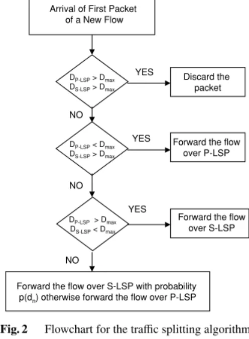
(4) IEICE TRANS. COMMUN., VOL.E87–B, NO.10 OCTOBER 2004. 2916 Table 1 The ABR source behavior. { if CI is set AT R := AT R − AT R ∗ RDF else if NI is not set AT R := AT R + RIF ∗ PT R AT R := min(AT R, PT R) } AT R := min(AT R, ER) AT R := max(AT R, MT R). to the minimum of the current ER value in the RM packet and the maximum rate the switch can support. Thus, every source sends at a rate no more than the ER calculated at its bottleneck point. Secondly, we assume a buffer size of B at the network buffers and the CI is set by the switch if the buffer occupancy of the switch is larger than BCI . As a third operation, the NI is set if the buffer occupancy of the switch is between BNI and BCI . When the sending source receives the ER, CI and NI information, traffic will be sent at a rate ATR (Allowed Traffic Rate) using the standard-based ABR source behavior given in Table 1. In this table, RDF and RIF correspond to Rate Decrease Factor and Rate Increase Factor, and MTR and PTR correspond to Minimum Traffic Rate and Peak Traffic Rate, respectively.. Fig. 2. Flowchart for the traffic splitting algorithm.. 3.3 Flow-Based Splitting In this subsection, we describe how traffic is split among the primary and secondary LSPs at the edge node. There are three stages in our proposed traffic splitting approach. The following operations will be performed in these three stages for every arriving IP packet. Source nodes (also called ingress Label Switch Router—LSR in MPLS jargon) are edge nodes that collect IP traffic from the access network and decide on the destination node (or called egress LSR) for every packet, using an exterior gateway routing protocol (e.g., BGP4). In the first stage of our architecture, IP packets are classified on a per-destination (or per -egress LSR) basis. Then for each destination node, we identify IP traffic flows and maintain a list which keeps track of each active flow. Similar to [20], we propose to use a hash on the source and destination IP addresses and source and destination ports to identify IP flows. If this new hash is in the current active hash list, then it implies that this packet is part of an active flow and the IP packet should be forwarded after MPLS encapsulation over the previously assigned LSP for that flow. We stress the fact that we do not propose per-flow LSPs or per-flow queuing. A flow is said to be active or a hash is kept in the active hash list if a packet for that flow has arrived within the last T out seconds. Otherwise, that flow is said to timeout and it is deleted from the list of active flows. When a packet arrives which does not belong to any flow in the list, a new active flow is inserted into the list. In the second stage, a silver queue and a bronze queue are maintained at ingress LSRs for every egress LSR. Both queues are drained using the ATR information calculated by using the ABR source behavior. In this stage, we decide. Fig. 3. The traffic splitting function p(d).. which service queue each flow should join. When a packet arrives which is not associated with an existing active flow, a decision on how to forward the packets of this new flow needs to be made. For this purpose, we calculate the DP−LS P and DS −LS P delay estimates for the silver and bronze queues in the edge node, respectively. These two delays are estimated by dividing the corresponding queue occupancy by the drain rate ATR of that queue. The notation dn denotes the moving averaged difference between the delay estimates at the epoch of the nth packet arrival and is updated as follows: dn = γ(DP−LS P − DS −LS P ) + (1 − γ)dn−1. (1). where γ is the averaging parameter to be set by the network operator. We also use the notation Dmax to denote the maximum allowable delay for a packet through the MPLS backbone network. For flow management and routing, we propose the algorithm given in Fig. 2 that applies to the first packet of every new active flow. The probability p(·) is described in Fig. 3 which is similar to the Random Early.
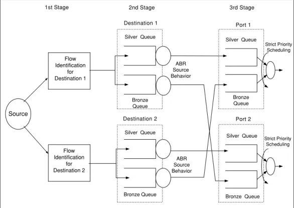
(5) AKAR et al.: AVAILABLE BIT RATE TRAFFIC ENGINEERING. 2917. Fig. 4. MPLS edge node architecture with two destination nodes and two physical ports.. Detection (RED) curve used for active queue management [26]. We call the policy we use for multipath traffic engineering the Random Early Reroute (RER) policy. RED’s goal is to control the average queue occupancy, whereas in multipath traffic engineering, it is the average delay difference between the two queues that is controlled by RER. We note that by RER, we favor the choice of the min-hop path to deal with the knock-on effect. Once an LSP is decided upon the arrival of the first packet of a new flow, all successive packets of the same flow will then be forwarded over the same LSP if delay constraints are satisfied. If the first packet of a new flow is discarded because of a delay constraint violation, then the traffic splitting algorithm in Fig. 2 will have to apply to the second packet of the same flow to decide onto which LSP to forward the flow. In the third stage, we employ per-class queuing at each physical port. The three stage traffic splitting mechanism is depicted in Fig. 4 for an MPLS edge node with two destinations and two physical ports. In this example, we assume the primary and secondary LSPs for destination node 1 use Port 1 and Port 2, and the primary and secondary LSPs for destination node 2 use Port 2 and Port 1, respectively (the gold queue in the third stage is not shown in this figure). We note that this three-stage mechanism applies only to new IP packets arriving at the MPLS domain. The transit traffic bypasses the first two stages and those transit packets only go through per-class queuing.. 4.. Simulation Study. In this section, the simulation results are presented to validate the proposed traffic engineering architecture. The platform we use is an event-driven packet-based MPLS simulator that we implemented from scratch using the Java programming language. Recently, there has been a surge of interest in flow based Internet traffic modeling, see [27] and the references therein. In [28], an M/G/∞ model is proposed for the number of active flows on a backbone link. In this model, flow arrivals are Poisson and the size of the flows are generally distributed which includes heavy tailed document lengths transferred over the Internet [29]. The packet arrival rates within a flow are fixed and identical across the flows in the model of [28] but generalizations to varying rates are possible [27]. In the current simulation study, we use a sub-case of the M/G/∞ model of [28] focusing only on either deterministic or geometrically distributed flow sizes for the sake of a first order analysis. The simulator allows us to specify the network topology and the traffic demand matrix. Let T i j (in bps) denote the long term average traffic demand between nodes i and j and let T = {T i j } denote the traffic demand matrix. The individual flow arrival process between nodes i and j is assumed to be Poisson with rate λi j (flows/s). Each flow consists of a random number of packets with mean M f where each packet is of fixed length L p (in bytes). The packet arrival process within a flow is assumed to be inelastic (e.g., UDP flows).
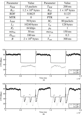
(6) IEICE TRANS. COMMUN., VOL.E87–B, NO.10 OCTOBER 2004. 2918. in this study and is modeled by a Poisson distribution with mean R f bps. The case of elastic flows (e.g., TCP flows) are left for future study. The mean flow size in bytes is denoted by L f = M f L p . We note that when the flow size distribution is kept fixed, increasing the long term traffic demand between an s-d pair leads to a larger average number of active flows at a given instant between the same pair. The simulator reports Current Traffic Rate (CTR) for each LSP which is the traffic injection rate (in Mbps) from the source node towards the network. The number of total injected bits throughout an averaging interval is first counted and this number is then divided by the averaging interval to find the CTR of this LSP. Loss Rate (LR) for a given s-d pair is defined as the ratio of the number of rejected/lost bits to the number of total incoming bits for that pair. We note that an incoming packet may either be rejected at the source node because of delay constraints or it can be dropped within the network because of congestion. The NLR (Network LR) is used for indicating the network-wide loss rate as a whole. In our simulation studies, each flow associates a sequence number to its packets. If the sequence number of the currently arriving packet at the destination node is smaller than the sequence number of the previously arrived packet, then the current packet is counted as an “out of order packet.” ROR (Reordering Rate) for an s-d pair is then defined as the ratio of out of order packets to all packets belonging to this pair. NROR (Network ROR) denotes the network-wide reordering rate. We will refer to the traffic engineering method described in the previous section as Flow-Based MultiPath Routing (FBMPR). When the traffic splitting policy given in Fig. 2 not only applies to the first packet of each new flow but to all packets without flow classification, we then use the term Packet-Based MPR (PBMPR) for the underlying routing method. We note that PBMPR does not take into consideration the packet reordering within a flow and therefore routes packets of the same flow independently over either the P-LSP or the S-LSP. PBMPR may achieve higher resource utilization compared to FBMPR since load balancing is done on a per-packet basis. The drawback of using PBMPR is that packet reordering can cause significant throughput degradation at the application level [20], [21]. Single Path Routing (SPR) refers to the case when the S-LSP is absent in the system. SPR should be viewed as the MPLS counterpart of a flow controlled best-effort ATM network using the ABR service. In our simulation study, we compare and contrast the methods SPR, FBMPR, and PBMPR in terms of their network-wide loss rates (NLR) and reordering rates (NROR). Unless otherwise stated, the algorithm parameters in Table 2 will be used throughout the simulation study. In the current paper, we use two different topologies i) a simple 3node ring topology to study the transient performance of the proposed approach, ii) a moderately-sized mesh topology (the so-called hypothetic US topology), to study the effect of flow model parameters on performance and to validate the ability of the architecture to mitigate the knock-on effect. Table 2 Problem parameters used throughout the simulation study (unless otherwise stated). Parameter NRM BCI RDF MTR LRM Lf Rf minth Dmax B. Value 15 packets 1.2 × 106 bytes 0.0625 0 50 bytes 10240 bytes 64 kbps 30 ms 180 ms 2 × 106 bytes. Parameter T RM BNI RIF PTR Mf Lp p0 maxth γ T out. Value 200 ms 1 × 106 bytes 0.125 ∞ 80 packets 128 bytes 1 150 ms 0.3 300 ms. Fig. 5 Current traffic rate graph from node 1 to 0 when (a) PBMPR is employed (b) FBMPR is employed.. in realistically-sized networks. 4.1 3-Node Ring Topology In this example, we present the performance of FBMPR when the network parameters change in short time scales (we use deterministic flow lengths in this part). For this purpose, we use a simple three node ring topology where the nodes are numbered 0, 1, 2. We assume a symmetric traffic demand of 80 Mbps between nodes 0 and 1. The link from node 1 to node 0 is assumed to have a capacity that alternates between 100 Mbps and 50 Mbps. In particular, we assume a 100 Mbps capacity in the interval (0 s, 5 s), 50 Mbps in the interval (5 s, 10 s), and so on. For the traffic between node 1 and 0, we assume two LSPs, the P-LSP using the direct path, and the S-LSP using the indirect path via node 2. In Fig. 5(a), the CTRs for the P-LSP and S-LSP from node 1 to node 0 are depicted when the method PBMPR is employed. Initially, the P-LSP is able to carry all traffic from node 1 to node 0. However, when the link capacity between node 1 and node 0 drops to 50 Mbps, this link is not able to carry the 80 Mbps traffic demand. In this case, the P-LSP carries about 47 Mbps traffic of the overall 80 Mbps traffic demand and the S-LSP carries about 33 Mbps. In Fig. 5(b), we plot.
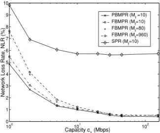
(7) AKAR et al.: AVAILABLE BIT RATE TRAFFIC ENGINEERING. 2919. CTR with respect to time for the two LSPs from node 1 to node 0 when FBMPR is employed. The CTRs for both PBMPR and FBMPR show similar average behavior when the network conditions vary, however, the FBMPR response is more oscillatory. For this oscillatory behavior, we note that all the packets of the same flow are forwarded using the same LSP in FBMPR, and the decision made for the first packet of a particular flow applies to all packets belonging to the same flow. Therefore there will be decision epochs when all the new flows are forwarded over the new LSP whereas the already active flows using the old LSP can still saturate the corresponding queue of the latter LSP. This phenomenon occasionally leads to underutilization in one queue and over-utilization in the other and therefore oscillatory behavior. We view the oscillatory response as the price we pay for the elimination of packet reordering. We also monitored the long run network-wide loss rates for this scenario; we find NLR to be 0.478% for FBMPR and 0 when PBMPR is applied. However, we also note that NROR is zero with FBMPR and 10.350% for PBMPR. In our simulations, we do not attempt to quantify the effect of the packet reordering rate on the application-level throughput, but it has been noted in the literature that this level of NROR may cause severe degradation in the user-perceived performance [20], [21].. Fig. 6. The hypothetic dense US topology used in our simulation study.. 4.2 Mesh Topology The algorithm FBMPR is tested for different flow model parameters in a publicly available test network given in Fig. 6 which consists of 12 nodes and 19 links. This test network is available at the URL: www.fictitious.org/omp together with the traffic demand matrix and is called the hypothetic dense US topology. All the links in this test network have capacity c1 = 155 Mbps except for the links de-ch and ch-cl which have c2 = 2c1 = 310 Mbps capacity in both directions. We first study the effect of the flow arrival rates on the performance of FBMPR for the hypothetic US topology. We assume geometrically distributed flow lengths for flow generation to introduce randomness. We first scale the link capacities c1 , c2 , and the traffic demands T i j together by a multiplicative constant so as to vary λi j . We note that the flow arrival rates are related to the traffic demands by λi j =. Ti j 8M f L p. (2). We compare and contrast the three methods SPR, PBMPR, and FBMPR when the link capacities are varied as well as the mean flow length M f . The results are depicted in Fig. 7. The x-axis of Fig. 7 is the logarithm of the capacity parameter c1 in Mbps which is the capacity of the 17 links in the hypothetic dense US topology whereas the remaining two links de-ch and ch-cl would have twice as much capacity (i.e., c2 ). We note that the mean flow size M f does not have much impact on the performance of SPR and PBMPR since these algorithms are not flow aware. Therefore, only the M f = 10 results are depicted in Fig. 7 for SPR and PBMPR.. Fig. 7. NLR vs. the logarithm of the link capacity parameter c1 .. Furthermore, we observe that the NLRs for PBMPR and SPR decrease with increasing link capacities which can be explained through the statistical multiplexing concept. The same effect can also be seen in the FBMPR case and moreover there is further improvement in terms of NLR; the NLR for FBMPR approaches to that of the PBMPR case when the link capacities are increased and they are very close when the link capacity c1 is larger than 45 Mbps for all three tested values of the mean flow length M f . As expected, when the link capacities are relatively small (i.e., c1 close to 1 Mbps), the performance of FBMPR deviates considerably from that of the PBMPR. We note that in this regime, better performance for FBMPR is obtained with shorter flows; the case of M f = 10 outperforms the cases M f = 80 and M f = 960 in terms of NLR. This phenomenon can be explained by observing the relationship between flow-based traffic splitting and the flow arrival rates; the larger the flow arrival rates the more the number of decision epochs to split traffic. Increasing the control frequency improves the performance of the controlled system. If, on the other hand, there are fewer flow arrivals in unit time, fewer traffic splitting decisions would take place leading to over- or under-utilization of the associated silver and bronze queues maintained at the edge nodes. We now address the knock-on effect. Unlike the orig-.
(8) IEICE TRANS. COMMUN., VOL.E87–B, NO.10 OCTOBER 2004. 2920 Table 3 Percentage throughputs obtained with FBMPR, FBMPR-SQ, and FBMPR-SQ-MD, for five different connectivity scenarios. Topo. A B C D E. PLR 1.51 1.61 2.04 2.25 2.67. FBMPR 99.351 94.363 87.282 74.527 61.675. FBMPR-SQ 99.857 95.905 82.020 61.378 39.261. FBMPR-SQ-MD 88.460 83.023 66.078 49.273 34.594. inal test network, we fix c1 = 45 Mbps (as opposed to the original 155 Mbps) except for the links de-ch and chcl which have c2 = 90 Mbps. We also scale down the test traffic demand matrix accordingly. We consider the following topologies all generated out of the original hypothetic dense US topology given in Fig. 6 by preserving the nodes but changing the interconnectivity of the original topology: • • • • •. A: original hypothetic US topology B: delete links dc-sl and dc-cl from A C: delete links da-hs and sl-cl from B D: delete links sf-sj and la-sj from C E: add sf-sj back and delete sf-de and de-sj from D (i.e., connect all nodes via a ring). We also keep the traffic demand matrix fixed for all topologies. In our proposed architecture, we have two instruments to cope with the knock-on effect: i) the MPLS strict-priority queuing architecture given in Fig. 1 that favors traffic belonging to P-LSPs, ii) the RER policy in Fig. 3 that favors the P-LSP over the S-LSP. These instruments both have the goal of ensuring that source nodes never send traffic to secondary paths of longer length before they make full use of their primary paths. In order to show the effectiveness of the proposed architecture, we first remove the first instrument i), or equivalently we use a single queue for traffic from both P-LSPs and S-LSPs, but keep the second instrument ii). We call this scheme FBMPR-SQ (SQ refers to Single Queue). We then remove the second instrument as well and instead of a RER policy that favors P-LSPs, we simply choose the path with lower average delay (i.e., equivalent to setting minth = maxth = 0, p0 = 1). We call this method FBMPR-SQ-MD (MD refers to Minimum Delay path selection irrespective of the path type). The network-wide percentage throughput (defined as 100(1 − NLR)) for FBMPR, FBMPR-SQ, and FBMPR-SQ-MD are given in Table 3 for the five topologies given above. The second column of Table 3 is PLR (Path Length Ratio) which is the ratio of the average hop length of the S-LSPs to the average hop length of the P-LSPs. As we move from a densely connected topology to a sparse one, the PLR increases as given in Table 3. The “primary path first” scheme FBMPR significantly outperforms FBMPR-SQ-MD for all the studied topologies in terms of throughput where the associated performance gain changes in proportion with PLR. Table 3 also shows that for sparsely connected topologies, it is preferable to use both the two instruments i) and ii) to cope with the knock-on effect as FBMPR outperforms FBMPR-SQ in these scenarios. However we also note that for densely connected topologies, we. obtained close results for FBMPR and FBMPR-SQ which leads us to believe that using differentiated services in the core nodes may not be as crucial in densely interconnected networks where the PLR is relatively smaller. 5.. Conclusions. In this paper, we propose a multipath traffic engineering architecture in IP networks with MPLS backbones. This architecture is shown to eliminate the so-called knock-on effect which is observed in some traditional load balancing algorithms. For traffic splitting purposes, we use a variant of the ABR protocol designed for flow control in ATM networks. We show that it is possible to do traffic engineering in short time scales due to the promptness of the ABR explicit-rate feedback mechanism. Moreover, the proposed traffic engineering architecture avoids out-of-order packets using flowbased multipath routing. The performance of the proposed traffic engineering architecture is shown to depend on the network speeds and the average flow sizes. We conclude that this architecture is applicable to flow-rich national/regional backbone provider scenarios where the average number of flow arrivals in unit time is large enough to validate the flowbased traffic engineering approach. Future work will consist of using more realistic traffic models for the Internet and their implications on reordering-free multipath traffic engineering. Acknowledgement This work is supported in part by The Scientific and ¨ ˙ITAK) under Technical Research Council of Turkey (TUB projects EEEAG-101E025 and EEEAG-101E048. The authors would also like to thank M. Atik for his contributions to the development of the MPLS simulator. References [1] N. Akar, I. Hokelek, M. Atik, and E. Karasan, “A reordering-free multipath traffic engineering architecture for Diffserv-MPLS networks,” Proc. 3rd IEEE Workshop on IP Operations and Management, pp.107–113, Kansas City, MO, USA, 2003. [2] D.O. Awduche, A. Chiu, A. Elwalid, I. Widjaja, and X. Xiao, “Overview and principles of Internet traffic engineering,” IETF Informational RFC-3272, May 2002. [3] L. Berry, S. Kohler, D. Staehle, and P. Trangia, “Fast heuristics for optimal routing in IP networks,” Tech. Rep. 262, Universitat Wurzburg Institut fur Informatik Research Report Series, July 2000. [4] B. Fortz and M. Thorup, “Internet traffic engineering by optimizing OSPF weights,” Proc. INFOCOM, pp.519–528, Tel-Aviv, Israel, 2000. [5] Y. Wang, Z. Wang, and L. Zhang, “Internet traffic engineering without full mesh overlaying,” Proc. INFOCOM, pp.565–571, Anchorage, USA, 2001. [6] A. Elwalid, C. Jin, S. Low, and I. Widjaja, “MATE: MPLS adaptive traffic engineering,” Proc. INFOCOM, pp.1300–1309, Anchorage, USA, 2001. [7] E. Rosen, A. Viswanathan, and R. Callon, “Multiprotocol label switching architecture,” RFC 2481, Jan. 2001. [8] M. Kodialam and T.V. Lakshman, “Minimum interference routing with applications to MPLS traffic engineering,” Proc. INFOCOM,.
(9) AKAR et al.: AVAILABLE BIT RATE TRAFFIC ENGINEERING. 2921. pp.884–893, Tel-Aviv, Israel, March 2000. [9] S. Plotkin, “Competetive routing of virtual circuits in ATM networks,” IEEE J. Sel. Areas Commun., vol.13, no.6, pp.1128–1136, 1995. [10] A. Girard, Routing and Dimensioning in Circuit Switched Networks, Addison-Wesley, 1990. [11] F.P. Kelly, “Network routing,” Philosophical Transactions: Physical Sciences and Engineering, vol.337, pp.343–367, 1991. [12] M. Schwartz, Telecommunication Networks: Protocols, Modeling, and Analysis, Addison-Wesley, 1987. [13] R.S. Krupp, “Stabilization of alternate routing networks,” International Communications Conference, Philadelphia, USA, 1981. [14] F.P. Kelly, “Routing in circuit switched networks: Optimization, shadow prices and decentralization,” Advances in Applied Probability, vol.20, pp.112–144, 1988. [15] S. Nelakuditi, Z.L. Zhang, and R.P. Tsang, “Adaptive proportional routing: A localized QoS routing approach,” Proc. INFOCOM, pp.1566–1575, Tel Aviv, Israel, 2000. [16] S. Bahk and M.E. Zarki, “Dynamic multi-path routing and how it compares with other dynamic routing algorithms for high speed wide area networks,” ACM SIGCOMM, pp.53–64, 1992. [17] D.M. Chiu and R. Jain, “Analysis of the increase/decrease algorithms for congestion avoidance in computer networks,” Computer Networks and ISDN Systems, vol.17, no.1, pp.1–14, June 1989. [18] V. Jacobson, “Congestion avoidance and control,” ACM Computer Communication Review, vol.18, no.4, pp.314–329, 1988. [19] J. Wang, S. Patek, H. Wang, and J. Liebeherr, “Traffic engineering with AIMD in MPLS networks,” 7th IFIP/IEEE International Workshop on Protocols for High-Speed Networks, pp.192–210, Berlin, Germany, 2002. [20] Z. Cao, Z. Wang, and E.W. Zegura, “Performance of hashing-based schemes for Internet load balancing,” Proc. INFOCOM, pp.332– 341, Tel Aviv, Israel, 2000. [21] M. Laor and L. Gendel, “The effect of packet reordering in a backbone link on application throughput,” IEEE Network Magazine, vol.16, no.5, pp.28–36, 2002. [22] Y. Lee and Y. Choi, “An adaptive flow-level load control scheme for multipath forwarding,” Networking—ICN 2001, pp.771–779, Colmar, France, 2001. [23] A. Shaikh, J. Rexford, and K.G. Shin, “Load-sensitive routing of long-lived IP flows,” Proc. ACM SIGCOMM, pp.215–226, Cambridge, USA, 1999. [24] F.L. Faucheur, L. Wu, B. Davie, S. Davari, P. Vaananen, R. Krishnan, and P.C.J. Heinanen, “MPLS support of differentiated services,” RFC 3270, May 2002. [25] S. Kalyanaraman, R. Jain, S. Fahmy, R. Goyal, and B. Vandalore, “The ERICA switch algorithm for ABR traffic management in ATM networks,” IEEE/ACM Trans. Netw., vol.8, no.1, pp.87–98, 2000. [26] S. Floyd and V. Jacobson, “Random early detection gateways for congestion avoidance,” IEEE/ACM Trans. Netw., vol.1, no.4, pp.397–413, 1993. [27] C. Barakat, P. Thiran, G. Iannaccone, C. Diot, and P. Owezarski, “A flow-based model for Internet backbone traffic,” Proc. INFOCOM, New York, USA, 2003. [28] S.B. Fredj, T. Bonald, A. Proutiere, G. Regnie, and J.W. Roberts, “Statistical bandwidth sharing: A study of congestion control at flow level,” Proc. ACM SIGCOMM 2001, San Diego, CA, USA, Aug. 2001. [29] M. Crovella and A. Bestavros, “Self-similarity in World Wide Web traffic: Evidence and possible causes,” IEEE/ACM Trans. Netw., vol.5, no.6, pp.835–846, 1997.. Nail Akar received the B.S. degree from Middle East Technical University, Turkey, in 1987 and M.S. and Ph.D. degrees from Bilkent University, Turkey, in 1989 and 1994, respectively, all in electrical and electronics engineering. From 1994 to 1996, he was a visiting scholar and a visiting assistant professor in the Computer Science Telecommunications program at the University of Missouri-Kansas City. In 1996, he joined the Technology Planning and Integration group at the Long Distance Division, Sprint, where he held a senior member of technical staff position from 1999 to 2000. Since 2000, he is an assistant professor at Bilkent University. His current research interests include performance analysis of computer and communication networks, queuing systems, traffic engineering, network control and resource allocation, and multimedia networking.. ˙ Ibrahim H¨okelek received the B.S. and M.S. degrees in electrical and electronics engineering from Bilkent University, Ankara, Turkey in 2000 and 2002, respectively. He is currently studying toward Ph.D. degree in electrical engineering at the City College of the City University of New York. His current research interests are on mobile ad-hoc networks.. Ezhan Karasan received the B.S. degree from Middle East Technical University, Ankara, Turkey, the B.S. degree from Bilkent University, Ankara, Turkey, and the Ph.D. degree from Rutgers University, Piscataway, New Jersey, all in electrical engineering, in 1987, 1990, and 1995, respectively. During 1995–1996, he was a post-doctorate researcher at Bell Labs, Holmdel, New Jersey. From 1996 to 1998, he was a Senior Technical Staff Member in the Lightwave Networks Research Department at AT&T LabsResearch, Red Bank, New Jersey. Since 1998, he has been an assistant professor in the Electrical and Electronics Engineering Department at Bilkent University, Ankara, Turkey. His current research interests are in the application of optimization and performance analysis tools for the design and analysis of wireless ad hoc networks and optical burst/packet switching networks..
(10)
Şekil
+3

Benzer Belgeler
We propose a new algorithm to solve lot sizing, tool allocation and machining conditions optimization problems simultaneously to minimize total production cost in a CNC
Keywords : Speech coding, lineiir predictive coding, vocal tract parameters, pitch, code excited linear prediction, line spectrum
Keywords: Capacitive Micromachined Ultrasonic Transducers, Circular CMUT, MEMS, Lumped Element Model, Equivalent Circuit Model, Collapsed Mode, Collapsed CMUT Array, Collapsed
Angular Force Constant, κ (eV/rad 2 ) and Angular Frequency, ω (rad/s) Values of Selected Edge-Passivated Phosphorene Nano flakes β-PNFH and α-PNFH on Various Monolayer
A model system for testing both the sense and antisense promoter activities has been constructed and a possible transcriptional interference between sense and
As will be discussed in the next chapter, qutrit (2. 20) may manifest entan- glement in the case of single spin-qutrit system, while single true qutrit can never be entangled... Let
The discussions in the previous chapters showed clearly that fantasy texts can be activated in many ways using various mechanisms. This is the indicator that Saga fantasy genre
Geometric band properties in strained monolayer transition metal dichalcogenides using simple band structures.. Cite
