PERFORMANCE ANALYSIS OF DIVERSITY
TECHNIQUES FOR OFDM AND BASE STATION
COOPERATION
a thesis
submitted to the department of electrical and
electronics engineering
and the institute of engineering and sciences
of bilkent university
in partial fulfillment of the requirements
for the degree of
master of science
By
Hande ¨
Uzeler
January 2010
I certify that I have read this thesis and that in my opinion it is fully adequate, in scope and in quality, as a thesis for the degree of Master of Science.
Assist. Prof. Dr. Defne Akta¸s (Supervisor)
I certify that I have read this thesis and that in my opinion it is fully adequate, in scope and in quality, as a thesis for the degree of Master of Science.
Prof. Dr. Erdal Arıkan
I certify that I have read this thesis and that in my opinion it is fully adequate, in scope and in quality, as a thesis for the degree of Master of Science.
Assoc. Prof. Dr. Ali ¨Ozg¨ur Yılmaz
Approved for the Institute of Engineering and Sciences:
Prof. Dr. Mehmet Baray
ABSTRACT
PERFORMANCE ANALYSIS OF DIVERSITY
TECHNIQUES FOR OFDM AND BASE STATION
COOPERATION
Hande ¨
Uzeler
M.S. in Electrical and Electronics Engineering
Supervisor: Assist. Prof. Dr. Defne Akta¸s
January 2010
The main goal of the next generation wireless communication systems is to provide high data rate services. In order to deal with performance-limiting chal-lenges that include frequency selective fading channels, power and bandwidth constraints, multiple input multiple output (MIMO) and orthogonal frequency division multiplexing (OFDM) techniques have been proposed as effective tech-niques to combat fading and to provide high rate reliable transmission. In this thesis we first give an overview of WiMAX as an example of an OFDM system and study the performance of the WiMAX physical layer under different MIMO techniques. We also analyze space-frequency coding and propose a threaded algebraic space-time (TAST) based code.
Secondly, since the mobile bandwidth is an expensive and scarce resource, it seems likely that a high frequency reuse will be employed in the future cellular networks to increase spectral efficiency. This means that base stations (BSs) will operate in the same frequency band and therefore cause cochannel interference (CCI) to the users at other cells. CCI is an important performance degrading factor. Therefore our second aim is to investigate BS cooperation techniques to mitigate CCI. We assume that channel state information (CSI) is available at the cooperating BSs and analyze the performance gains due to cooperation when used in conjunction with Alamouti space-time coding.
Keywords: Multiple Input Multiple Output (MIMO), Orthogonal Frequency Division Multiplexing (OFDM), Space-Time Coding, Space-Frequency Coding, Base Station Cooperation, Distributed Space-Time Coding.
¨
OZET
C
¸ ES¸˙ITLEME TEKN˙IKLER˙IN˙IN D˙IKGEN FREKANS
B ¨
OLMEL˙I C
¸ O ˘
GULLAMALI S˙ISTEMLERDE VE TELS˙IZ
ER˙IS¸˙IM TERM˙INALLER˙IN˙IN ˙IS¸B˙IRL˙I ˘
G˙I ALTINDA
BAS¸ARIMLARININ ANAL˙IZ˙I
Hande ¨
Uzeler
Elektrik ve Elektronik M¨uhendisli˘gi Y¨uksek Lisans
Tez Y¨oneticisi: Yar. Do¸c. Dr. Defne Akta¸s
Ocak 2010
Yeni ku¸sak ileti¸sim sistemlerinin ana amacı y¨uksek veri hızı sa˘glayabilmektir. Frekansa ba˘gımlı s¨on¨umleme, bant geni¸sli˘gi ve g¨u¸c kısıtlamaları gibi ba¸sarımı kısıtlayan etkenlerle m¨ucadele etmek i¸cin ¸cok girdili ¸cok ¸cıktılı (MIMO) ve dik-gen frekans b¨olmeli ¸co˘gullama (OFDM) teknikleri sa˘gladıkları g¨uvenilir iletim ve frekans se¸cicili˘gine kar¸sı etkinliklerinden dolayı ¨onerilmektedir. Bu tezde ilk ¨once OFDM tekni˘gi i¸cin ¨ornek olarak WiMAX (IEEE 802.16 standardı) tanıtıldıktan sonra fiziksel katmanın ba¸sarımı farklı MIMO teknikleri altında incelendi. Ayrıca cebirsel uzay-zaman kodlarını kullanarak bir uzay-frekans kodu ¨onerildi.
Frekans spektrumu pahalı ve kıt bir kaynak oldu˘gundan, gelecekteki h¨ucresel a˘gların spektral verimlili˘gi arttırmak i¸cin y¨uksek bir frekans yeniden kullanım fakt¨or¨une ihtiya¸cları vardır. Bunun i¸cin telsiz eri¸sim terminallerinin aynı frekans bantını kullanması gerekmektedir ve bu durum kullanıcıların ¨onemli ¨ol¸c¨ude or-tak kanal giri¸simine (CCI) maruz kalmalarına neden olmaktadır. Oror-tak kanal giri¸simi ba¸sarımı kısıtlayan ¨onemli bir etmendir bu y¨uzden tezin ikinci amacı ortak kanal giri¸simini azaltan telsiz eri¸sim terminalleri i¸sbirli˘gi tekniklerini in-celemektir. Kanal durum bilgisinin telsiz eri¸sim terminallerinde mevcut oldu˘gu varsayılarak telsiz eri¸sim terminalleri i¸sbirli˘gi tekniklerinin Alamouti uzay-zaman kodlaması ile birlikte kullanıldı˘gında olu¸san ba¸sarım kazan¸cları analiz edildi. Anahtar Kelimeler: C¸ ok Girdili C¸ ok C¸ ıktılı Sistemler, Dikgen Frekans B¨olmeli C¸ o˘gullama, Uzay-Zaman Kodlama, Uzay-Frekans Kodlama, Telsiz Eri¸sim Ter-minallerinin ˙I¸sbirli˘gi, Da˘gıtılmı¸s Uzay-Zaman Kodlama
ACKNOWLEDGMENTS
I would like to express my sincere gratitude to my supervisor Assist. Prof. Dr. Defne Akta¸s for her guidance, support, and encouragement throughout the course of this work. I am also grateful to Professors Erdal Arıkan and Ali ¨Ozg¨ur Yılmaz for being members of my thesis defense committee.
I would also like to thank TUBITAK Career Program 107E199 Project and European Commission 7th Framework Programme WiMAGIC Project for their financial support.
Finally, the writing of this thesis would not have been possible without the continual support of my family and friends, to whom I am indebted.
Contents
1 Introduction 1
1.1 Motivation . . . 1
1.2 Literature Survey . . . 3
1.3 Contributions of This Thesis . . . 8
1.4 Thesis Organization . . . 8
1.5 Notation . . . 9
2 MIMO Communication Systems 10 2.1 The Wireless Channel . . . 10
2.1.1 Fading Effects Due to Delay Spread . . . 11
2.1.2 Fading Effects Due to Doppler Spread . . . 12
2.2 The MIMO Channel Model . . . 13
2.3 Diversity Techniques . . . 14
2.4 Space-Time Coding . . . 15
2.4.1 ST Code Design . . . 15
2.4.2 The Alamouti scheme . . . 18
3 MIMO-OFDM and Performance of WiMAX PHY Layer 21
3.1 Orthogonal Frequency Division Multiplexing . . . 21
3.2 MIMO-OFDM . . . 24
3.3 IEEE 802.16 PHY Layer . . . 26
3.3.1 MIMO Techniques in IEEE 802.16 . . . 29
3.4 Space-Frequency Coding . . . 31
3.4.1 TAST Framework for SF Coding . . . 35
3.4.2 A method for complexity reduction . . . 36
3.4.3 Reduced Complexity TAST SF Code . . . 38
3.5 Simulation Results . . . 41
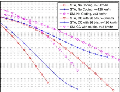
3.5.1 Performance without FEC . . . 44
3.5.2 Performance with FEC . . . 46
3.5.3 Performance with Intercarrier Interference . . . 54
3.6 Concluding Remarks . . . 56
4 Base Station Cooperation Using Alamouti Space-Time Coding 58 4.1 The System Model . . . 59
4.1.1 Zero-Forcing Methods . . . 60
4.1.2 Signal to Leakage Ratio Method . . . 61
4.2 Randomized Space-Time Coding . . . 62
4.3 Simulation Results . . . 65
List of Figures
2.1 The MIMO channel. . . 13
3.1 Overlapping subcarriers in an OFDM system. . . 22
3.2 Addition of the cyclic prefix to an OFDM symbol. . . 23
3.3 Block diagram of WiMAX PHY layer. . . 27
3.4 Performance of the system without FEC under v=3 km/hr. . . 44
3.5 Performance of the system without FEC under v=30 km/hr. . . . 45
3.6 Performance of the system without FEC under v=120 km/hr. . . 45
3.7 Effects of channel coding on performance. . . 47
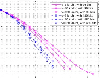
3.8 The effect of increasing FEC block size on ST-Alamouti and SM. 48 3.9 The effect of increasing FEC block size on ST-Alamouti for differ-ent subchannelization schemes. . . 49
3.10 Performance comparison of CTC and CC under v=3 km/hr. . . . 50
3.11 Performance comparison of different MIMO techniques with CTC under various user speeds. . . 50
3.12 Performance comparison of TAST code for different decoding com-plexities, v=3 km/hr. . . 51
3.13 Performance comparison of TAST code and Matrix A and B, v=3 km/hr. . . 52
3.15 Performance comparison of PUSC and band AMC. . . 54
3.16 Performance comparison with and without ICI for ST-Alamouti. . 56
3.17 Performance comparison with and without ICI for TAST code. . . 56
4.1 User locations. . . 66
4.2 User 1 performance with and without CC. . . 68
4.3 User 2 performance with and without CC. . . 68
4.4 User 3 performance with and without CC. . . 69
4.5 User 1 performance under various transmission schemes. . . 69
4.7 User 3 performance under various transmission schemes. . . 70
List of Tables
3.1 Simulation parameters . . . 42 3.2 Modified ITU channels . . . 43
List of Abbreviations
AMC Adaptive Modulation and Coding
BER Bit Error Rate
BLER Block Error Rate
BS Base Station
CCI Cochannel Interference
CC Convolutional Coding
CSI Channel State Information
CTC Convolutional Turbo Coding
CP Cyclic Prefix
FEC Forward Error Correction
FFT Fast Fourier Transform
i.i.d. Independent and Identically Distributed ICI Intercarrier Interference
ISI Intersymbol Interference
MS Mobile Station
MIMO Multiple Input Multiple Output
ML Maximum Likelihood
NLOS Non-Line-of-Sight
OFDM Orthogonal Frequency Division Multiplexing OFDMA Orthogonal Frequency Division Multiple Access
pcu Per Channel Use
PEP Pairwise Error Probability
PUSC Partial Usage of Subcarriers PHY Layer Physical Layer
SINR Signal to Interference plus Noise Ratio SLNR Signal to Leakage plus Noise Ratio
SF Space-Frequency
ST Space-Time
STC Space-Time Code
SM Spatial Multiplexing
SNR Signal to Noise Ratio
SVD Singular Value Decomposition
TAST Threaded Algebraic Space-Time
WiMAX Worldwide Interoperability for Microwave Access
Chapter 1
Introduction
In recent years, there has been a rapid growth in wireless communications driven by growing demand for emerging wideband services such as high-speed Internet access and high-quality multimedia transmission. The frequency spectrum or bandwidth is a limited resource, therefore to meet the demand for high data rate services the design of wireless communication systems that are capable of providing increased data rates and improved performance have become an active area of research.
The wireless channel presents a challenge for reliable communications because of factors such as multipath, mobility of the user or the surrounding environment and delays associated with multipath. Multipath occurs because a transmitted signal can be reflected, diffracted and refracted by the objects in the environment before reaching the receiver. Furthermore, the signal may follow multiple paths between the transmit and the receive antenna such that the received signal will consist of multiple delayed and attenuated copies of the transmitted signal which may add up destructively. The combination of all of these factors is called fading, a phenomenon which decreases the signal to noise ratio (SNR) of the received signal leading to a performance loss [1].
1.1
Motivation
One of the most promising solutions for combating fading and to improve system performance is to use multiple antennas at the transmitter and receiver. In a multiple-input multiple-output (MIMO) system with MT transmit and MR
receive antennas, diversity can be obtained from the MT× MRlinks between the transmitter and receiver. The basic idea behind diversity is to provide to the receiver a number of different replicas of the same transmitted signal such that these replicas may be combined in some way to improve the overall performance. However, when MIMO broadband channels are used for high data rate com-munication, multipath causes the channel to become a frequency selective channel which results in intersymbol interference (ISI) at the receiver and degrades the performance. In this case orthogonal frequency division multiplexing (OFDM), which is a multicarrier modulation scheme, may be used because it has high spec-tral efficiency and robustness against frequency selective channels. In OFDM, a frequency selective channel is transformed into a number of parallel frequency-flat subchannels, thereby reducing the receiver complexity by eliminating the need for time-domain equalization. The combination of OFDM and MIMO is a promising technique to meet the increasing high speed and reliability demands of the future. In fact, MIMO-OFDM is implemented in the IEEE 802.16 (World-wide Interoperability for Microwave Access (WiMAX)) standard.
The first objective of this thesis is to implement and simulate the MIMO techniques proposed in the IEEE 802.16 physical (PHY) layer using Matlab in order to have a better understanding of the standard and the system per-formance. This involves studying, through simulations, the various PHY layer coding schemes and MIMO techniques in the form of bit error rate (BER) and block error rate (BLER) performance under realistic channel models. As a part of the WiMAGIC project, which is an industry-driven research project aiming to develop novel and innovative solutions for WiMAX, our main goal is to investi-gate the existing MIMO techniques and make contributions towards new MIMO techniques which may be proposed to be employed in next generation WiMAX systems (IEEE 802.16m).
The second objective is to analyze the achievable gains when multiple base stations (BSs) cooperate with each other in an OFDM system. Most of the existing work on BS cooperation schemes consider single carrier systems therefore it is of interest to evaluate the performance of such schemes under an OFDM scenario since OFDM based systems, such as WiMAX, are expected to be in wide use in the future.
1.2
Literature Survey
Information theoretic results show that the capacity of a single link MIMO system with MT transmit and MR receive antennas increases linearly with min(MT, MR) [2,3]. However, for single-input single-output (SISO) channels capacity increases logarithmically with SNR therefore, the capacity of MIMO can be min(MT, MR) times larger than the SISO capacity. Therefore a significant capacity increase can be achieved by MIMO systems without increasing the transmit power and expanding the bandwidth.
Several practical transmission schemes have been proposed that utilize the MIMO channel in different ways, e.g., spatial multiplexing or space-time coding. In spatial multiplexing different signals are transmitted simultaneously by the transmit antennas in the same frequency band to provide a capacity gain which increases with the number of antennas. The first high data rate architecture was the Bell-Labs layered space-time architecture (BLAST) proposed in [4] which achieved the theoretical capacity limits of the MIMO architecture. In BLAST, multiple parallel data streams are spatially multiplexed and transmitted simulta-neously on the same frequency through all transmit antennas. With rich multi-path propagation, these different streams are separated at the receiver based on their distinct spatial signatures. However, due to exponential complexity of the optimal receivers, for practical implementations suboptimal receiver structures are used resulting in performance loss. Furthermore, inherent diversity in the channel is not exploited to its fullest extent.
For reliable communications, high spectral efficiency must be accompanied with low error rate. MIMO systems offer significant diversity advantages by exploiting multiple antennas at both the transmitter and receiver in order to obtain transmit and receive diversity and therefore increase the reliability of the system. Space-time (ST) coding relies on simultaneously coding across space and time to achieve diversity gain without sacrificing bandwidth [5].
The performance criteria for ST codes were derived in [6] and the diversity and coding gain associated with ST codes were also defined. Diversity gain describes the asymptotic decrease of the error rate as a function of SNR and coding gain describes the vertical shift of the error curve.
Over the years many different ST codes were described which can be classified into two major classes: ST trellis codes (STTC) and ST block codes (STBC).
STTC employ complex trellis encoding across multiple transmit antennas. When the number of antennas is fixed, the decoding complexity of STTC (measured by the number of trellis states at the decoder) increases exponentially as a function of the diversity level and transmission rate [6].
To achieve linear processing at the receiver, in [7] Alamouti proposed a novel transmit STBC diversity scheme where the transmitted symbols are mapped to a 2x2 space-time orthogonal transmission matrix. The orthogonal design achieves maximum likelihood (ML) decoding with linear processing per transmitted sym-bol. Extending Alamouti’s work, [8] proposed more general schemes referred to as orthogonal space-time block codes (OSTBC) for more than two transmit an-tennas. They showed that the orthogonal design couldn’t provide full rate (not more than rate 3/4 symbols per channel use (pcu)) for more than two transmit antennas with complex constellations. STBC has a very simple decoding pro-cess while retaining the full diversity. The STBC scheme supports maximum likelihood (ML) detection based only on linear processing at the receiver. How-ever, STBC can not provide an additional coding gain. Thus, STBC is typically concatenated with a bandwidth-efficient outer code.
To achieve spatial multiplexing gains with improved error performance some ST codes with rate greater than 1 symbol/pcu have been proposed [9, 10]. The increased spectral efficiency results in increased decoding complexity. Another class of ST codes based on algebraic number theory was proposed to achieve full diversity and high rate. In [11] threaded algebraic space-time (TAST) coding was proposed which made use of the layering concept. Here an algebraic code component [12, 13] is assigned to each thread and interleaved over space and time. A phase rotation is also applied to the layers such that the coded symbols can be sent as if they are transparent to each other. These codes also result in high decoder complexity due to joint detection of layers.
Most ST codes were developed for frequency nonselective (flat) channels and when used in broadband wireless communications, the frequency selective nature of the channel results in performance degradation due to ISI. OFDM is one of the most promising techniques for mitigating ISI without time domain equalization and it offers high spectral efficiency [14].
In frequency selective MIMO channels there is an additional source of di-versity due to the multiple propagation paths between the transmit and re-ceive antennas. This source of diversity is called frequency diversity and space-frequency (SF) coding has been proposed to combine the advantages of MIMO
and OFDM systems and exploit the spatial and frequency diversity available in the system [15–19]. In this coding scheme two-dimensional coding is applied to distribute symbols across space (transmit antennas) and frequency (OFDM subcarriers). The first SF coding scheme was proposed in [15] where existing ST codes were used by replacing the time domain with the frequency domain. In a straightforward way of realizing SF coding for two transmit antennas is to directly spread the Alamouti code over two subcarriers in one OFDM symbol [16]. The performance criteria for SF-coded MIMO-OFDM systems were derived in [18] and [20]. The maximum achievable diversity order was established as MTMRL, where L is the number of delay paths. It was also shown that in general existing ST codes cannot exploit the frequency diversity available in the frequency selective MIMO channel and it was suggested that a new code design procedure will have to be developed for MIMO-OFDM systems. When ST codes were directly used as SF codes the potential multipath diversity offered by the frequency selective channel is not exploited.
In [21], the authors of [18] proposed a SF code construction method by mul-tiplying the input symbols with a part of the discrete Fourier transform (DFT) matrix. The resulting SF codes achieve full diversity at the expense of band-width efficiency. In [19] a systematic design of full diversity SF block codes were proposed. This scheme relies on repeating each row of the underlying ST code matrix on L different subchannels in the same OFDM symbol and therefore in-curs spectral efficiency loss. The authors later proposed a design of full rate full diversity SF codes in [22]. In this scheme the information symbol vector is first coded via an algebraic rotation matrix and then mapped to different antennas and OFDM subcarriers. This way a rate of 1 symbol/pcu is achieved. It is im-portant to choose the rotation matrix carefully such that signal space diversity can be obtained [23]. This idea was further developed in [24] by incorporating the TAST framework to increase spectral efficiency and some examples of code designs were given. Inspired by this, we will investigate the performance of TAST SF codes.
The idea of coding across multiple OFDM symbols resulting in space-time-frequency (STF) codes was proposed in [24, 25]. Full diversity is only achievable if the number of OFDM symbols over which data is encoded is not smaller than the number of independently fading OFDM symbols spanned over one STF codeword. Therefore with the assumption that the MIMO channel stays constant over multiple OFDM symbols, it was shown that STF codes could not achieve
any additional diversity compared to SF codes. STF codes incur longer decoding delay and higher decoding complexity.
The techniques mentioned above focus on single cell single-user MIMO sys-tems. In cellular wireless systems BSs communicate with mobile stations (MSs) in their own cell. In conventional wireless systems, the co-existing BSs do not cooperate with each other. BSs transmit individually to their respective users and users treat the transmissions from other BSs as interference such that a mobile usually experiences several comparable and weak links from surrounding BSs. Therefore multiuser multicellular networks are limited by intercell cochan-nel interference (CC). This interference may be avoided by using frequency reuse at the expense of reduced spectral efficiency.
An alternative to the above noncooperative transmission scheme where each BS transmits to its respective MS is a cooperative transmission structure. It has been shown that performance gains are possible in multicell systems which use BS cooperation [26]. Since BSs are connected to each other via a high-speed optical fiber backbone, they can reliably exchange information among themselves. Therefore CC mitigation may be carried out at the transmitter (BS) side in the downlink, where complex structure and advanced processing can be more easily accommodated, if channel state information (CSI) can be obtained at the transmitter side either through uplink estimation or through a feedback channel. This may be possible for low user mobility scenarios such as indoor or outdoor pedestrian environments. Thus it is possible to coordinate the BS transmissions in order to mitigate CC in the downlink such that the MSs may receive useful signals, as opposed to interferences, from the cooperating BSs.
The information-theoretic characterization of the maximum sum capacity of MIMO broadcast systems with perfect CSI was based on the dirty-paper pre-coding technique [27]. It has been shown that the maximum sum capacity of a MIMO broadcast system with perfect CSI may be achieved by using dirty-paper codes [28]. However, due to the complexity of these schemes practical dirty-paper codes are not available. This has prompted the development of practical, subop-timal alternatives which can be categorized as linear transmission schemes such as zero-forcing (ZF) and minimum mean square error (MMSE) based precoding. The ZF schemes aim to perfectly cancel out the CC observed at each user by determining transmit beamformer weights which will force the interference to zero. Recently a ZF beamforming scheme making use of the pseudo-inverse of the channel matrix has been considered in [29] for the multiple-input single-output
(MISO) downlink setup under sum power constraints. It was shown that a ZF beamforming strategy can achieve the same asymptotic sum rate as the optimal dirty paper coding scheme as the number of users goes to infinity. Some other important ZF schemes have been proposed in [30–32]. The ZF schemes require that the number of transmit antennas be larger than or equal to sum of receive antennas of all users. When this condition is not met user scheduling algorithms may be implemented to ensure the dimension requirements.
Many iterative algorithms have also been proposed. For example the scheme in [31] is further improved in [33] by finding the transmit-receive antenna weights iteratively. We will not consider iterative algorithms here due to complexity issues.
Some schemes aim to choose the transmit beamformers in order to maximize signal to interference plus noise ratio (SINR). In this case the choice of one users beamformer may affect the crosstalk experienced by other users. Hence, the SINR values of all users are coupled, which makes SINR-based downlink beamforming a complicated task. The solution can be obtained iteratively due to the coupled nature of the optimization problem.
The uplink downlink duality has been used for the beamforming problem to maximize SINR. In [34–36], the uplink-downlink duality concept is introduced to find the optimum transmit-receive antenna weights and to allocate downlink power. The authors first show that the downlink SINR can be designed to be equal to the maximum uplink SINR under the same total available power but with a different power allocation in the downlink and uplink. They then propose a method to find the transmit weights and transmission powers that maximize the individual downlink SINR by solving its dual uplink equivalence.
An alternative approach to designing transmit beamforming vectors is given in [37] based on the concept of signal leakage. The term leakage is used to define the interference caused by the signal of a user on the remaining users and is a measure of how much signal power leaks into the other users.The criterion of choosing transmit weights is then based on maximizing signal to leakage plus noise ratio (SLNR). The advantage of this system is that the optimization prob-lem becomes decoupled and there exists a closed form solution. However, it does not completely eliminate CC and therefore users will experience some residual interference.
1.3
Contributions of This Thesis
The aim of this thesis is first to conduct a comprehensive performance evaluation and comparison of the ST/SF techniques in realistic MIMO-OFDM systems, in particular for a WiMAX system. We propose a SF scheme which has superior performance and resilience to high user speeds.
Secondly we aim to evaluate the performance gains of cooperative transmis-sion schemes to demonstrate the anticipated improvement of BS cooperation on the system performance while keeping the receiver complexity low. We propose a simple ZF scheme which performs as well as the no CC case.
1.4
Thesis Organization
The rest of the thesis is organized as follows. In Chapter 2, we will introduce some basic principles and concepts of the MIMO system, including channel model and diversity techniques, and some space-time coding schemes which will be necessary in the next chapters.
In Chapter 3, OFDM systems and SF coding are discussed. Firstly an intro-duction to OFDM systems is given. Then the SF coding techniques are reviewed and an introduction to TAST framework is presented. The proposed TAST based SF code is explained in detail. The chapter is concluded with the simulation re-sults of some ST and SF codes in a mobile WiMAX environment.
In Chapter 4, the cooperative transmission schemes are explained in detail and how transmitter beamformers are chosen such that CC is mitigated is dis-cussed. We will compare these schemes in a multicell environment taking into account the large scale fading components which were previously ignored in the single-cell case. Furthermore, we will incorporate the Alamouti scheme into our cooperative model and will analyze its performance in multi-user multicell envi-ronment.
Finally, we summarize our conclusions and provide some research directions for the future in Chapter 6.
1.5
Notation
Upper case bold letters, A, are used to denote matrices. Lower case bold letters, a, are used to denote column vectors. Aij is the element of matrix A on ith row and jth column. a
i denotes the ith element of column vector a. E[.] is the statistical expectation operator. |.| indicates the absolute value. (·)∗ repre-sents the complex conjugation operation. (·)T, (·)H and (·)−1 are the transpose, Hermitian transpose and inverse matrix operators respectively. IN denotes the N × N identity matrix. The Kronecker product operator is denoted by ⊗.
Chapter 2
MIMO Communication Systems
Channel fading degrades the performance of wireless transmissions significantly, and becomes the bottleneck for increasing data rates. Diversity techniques are popularly used to reduce the effect of channel fading and improve the reliability of transmission without increasing the transmitted power and sacrificing band-width. In MIMO systems, space-time coding can achieve bandwidth-efficient spatial diversity provided by multiple antennas over the fading channel.
In this chapter, we will first describe the characteristics of wireless communi-cation channels and give an introduction to MIMO systems. Then we will review diversity techniques and space-time coding schemes.
2.1
The Wireless Channel
Fading in a wireless channel can be classified into large and small-scale fading [1]. Large-scale fading describes the attenuation of the received signal over large dis-tances and is caused by path loss which is a function of distance, and shadowing by large objects such as buildings and hills. We will consider large-scale fading in Chapter 4 because in multicellular environments path loss becomes an impor-tant factor. Path loss is modeled by the path loss exponent n and the distance d between the base station and user. We can express path loss associated with distance d as P l = dn.
Small-scale fading refers to the dramatic changes of the received power level over small distances, or short periods of time. Small-scale fading is caused by the
constructive and destructive interference of the multiple signal paths between the transmitter and receiver. As a consequence of multipath fading, the deep fades experienced by the channel strongly impairs the performance of wireless communications. We can separate small-scale fading into two categories; fading effects due to delay spread and Doppler spread.
2.1.1
Fading Effects Due to Delay Spread
The received signal consists of the superposition of multiple copies of the trans-mitted signals that arrive at the receiver through different paths and at different times. This time dispersion is quantified by delay spread, denoted by στ. De-pending on the relationship between delay spread and symbol period, Ts, fading is classified as either frequency-flat or frequency selective fading. Delay spread can be characterized by the coherence bandwidth, Bc, in the frequency domain. Coherence bandwidth defines the range of frequencies over which the channel may be considered as flat. Coherence bandwidth and delay spread are inversely proportional to each other.
The channel exhibits frequency flat fading when the symbol period is larger than the delay spread, i.e., Ts >> στ. In this case, all of the received multipath components of a symbol arrive within the symbol time duration, hence there is no channel-induced intersymbol interference (ISI) distortion. There is still performance degradation due to the destructive superposition of the individual multipath components which can yield a reduction in SNR. When there is loss in SNR due to flat fading, the appropriate mitigation technique is to improve the received SNR or use more robust transmission techniques, such as space-time codes which are discussed in Section 2.4.
The channel exhibits frequency selective fading when Ts < στ. In this case, the time duration over which the multipath components of a symbol arrive at the receiver exceeds the symbol duration and therefore cause ISI. Frequency selective channels can be modeled by a tapped delay line. For a fading channel with L different paths, the possibly time-variant impulse response can be expressed as
h(τ ; t) = L−1 X l=0
α(l, t)δ(τ − τl(t)), (2.1)
where α(l, t) is the complex amplitude of the lthpath and τ
l(t) is the time delay of the lthpath at time t. In a non line-of-sight (NLOS) environment (i.e., when there
is no direct path between the transmitter and receiver), the impulse response h(τ ; t) is modeled as a zero-mean complex Gaussian process and the envelope |h(τ ; t)| has a Rayleigh distribution for any time t. Furthermore, the α(l, t)’s are zero-mean, independent and identically distributed (i.i.d) complex Gaussian random variables.
We assume that h(τ ; t) is wide-sense stationary and the autocorrelation func-tion is defined as [38]
φh(τ1, τ2; ∆t) = E [h∗(τ1; t)h(τ2; t + ∆t)] = φh(τ1; ∆t)δ(τ1− τ2), (2.2)
where ∆t is the observation time difference and the second equality follows from the fact that α(l, t)’s are uncorrelated. If we let ∆t = 0, the autocorrelation function φh(τ1; 0) = φh(τ1) is the average power output of the channel. For a
path delay τ , φh(τ ) is called the power delay profile of the frequency selective fading channel.
2.1.2
Fading Effects Due to Doppler Spread
The channel may also be time variable as a consequence of relative motion be-tween transmitter and receiver, or because of mobility in the environment. The characterization of the time variant nature of the channel can be done by Doppler spread and coherence time. Coherence time, Tc, is the time over which the two received signals have strong potential for amplitude correlation [1]. Depending on how long the coherence time is in comparison with the symbol duration, Ts, a fading channel can be categorized either as time flat (slow fading) or time se-lective (fast fading). The fading is time flat if the symbol duration is much less than the channel coherence time, i.e., Ts << Tc. The channel is time selective if Ts > Tc. In this case the channel changes over duration of one symbol period with high probability, which leads to distortion of the baseband pulse shape and irreducible error rate.
It is noted that frequency selectivity and time selectivity are two different properties of a fading channel. Taking into account combinations of time selec-tivity and frequency selecselec-tivity, fading channels are conventionally divided into one of the following four types,
• Flat fading channels (time and frequency flat)
• Time selective fading channels (time selective but frequency flat) • Doubly selective fading channels (both frequency and time selective).
2.2
The MIMO Channel Model
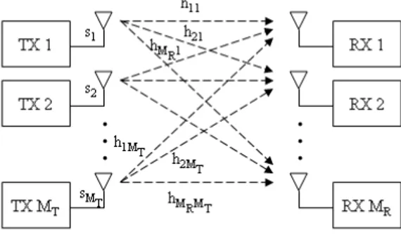
For a MIMO system with MT transmit and MR receive antennas, consider the system model given in Figure 2.1. It should be noted that the multiple trans-mit and receive antennas could belong to a single user modem or it could be distributed among different users or base stations for distributed MIMO config-uration and cooperative communications.
Figure 2.1: The MIMO channel.
At a certain time, assume that the K×1 modulated complex data symbols, s = [s1, s2, ..., sK]T, are mapped into a transmit vector consisting of complex symbols c = [c1, c2, ..., cMT]
T. Note that K is not necessarily equal to M
T. The transmit vector c is transmitted simultaneously from the MT transmit antennas. The received signal at antenna i can be expressed as,
yi = MT X
j=1
hijcj + ni, (2.3)
where hij is the channel coefficient from the jthtransmit antenna to the ithreceive antenna and the additive noise ni is a zero-mean complex Gaussian random variable with variance N0/2 per dimension. Combining the received signals in a
vector y = [y1, y2, ..., yMR]
T, (2.3) becomes
where n = [n1, n2, ..., nMR]
T and H is the M
R× MT channel matrix which can be expressed as, H = h11 h12 · · · h1MT h21 h22 · · · h2MT ... ... . .. ... hMR1 hMR2 · · · hMRMT . (2.5)
Note that this system model assumes that the channel undergoes flat fading and that the channel coefficients remain constant during the transmission of the symbol vector c.
2.3
Diversity Techniques
The most effective technique to combat fading relies on the exploitation of di-versity. In this section, we will discuss diversity techniques in space, time and frequency.
Time diversity can be achieved by transmitting the same messages in different time slots where the separation between the time interval is at least equal to the coherence time Tc of the channel. Time diversity can be provided by combining error control coding with interleaving where the replicas of the transmitted sig-nals are usually provided to the receiver in the form of redundancy in the time domain introduced by error control coding [39].
Depending on whether multiple antennas are used for transmission or recep-tion, two types of spatial diversity become available: receive-antenna diversity and transmit-antenna diversity. It should be noted that the multiple antennas must be physically separated by a proper distance so that the individual sig-nals are uncorrelated. In receive diversity, multiple antennas are deployed at the receiver to acquire independently faded copies of the transmitted signals which are then properly combined to mitigate channel fading to increase the overall received SNR.
Transmit diversity relies on multiple antennas at the transmitter. Transmit-antenna diversity schemes, can be divided into two categories: open loop and closed loop schemes. Closed loop schemes require channel knowledge at the transmitter, which is typically acquired through feedback channels. Although
feedback channels are present in most wireless systems, mobility may cause fast channel variations which cannot be tracked accurately by the transmitter.
Frequency diversity can be obtained via the frequencies separated by at least the coherence bandwidth of the channel and the frequencies are almost indepen-dent of each other. In wireless communications, the replicas of the transmitted signals are usually provided to the receiver in the form of redundancy in the fre-quency domain introduced by a multicarrier modulation such as OFDM, which will be discussed in detail in Chapter 3.
2.4
Space-Time Coding
In space-time (ST) coding joint encoding across multiple transmit antennas is carried out in order to maximize the reliability of a wireless link. ST coding schemes exploit spatial diversity in order to provide diversity and/or coding gains over an uncoded wireless link [6, 7].
The concept of ST coding was first introduced and the design criteria were established in [6]. In this section we will review these criteria.
2.4.1
ST Code Design
Consider the space-time coded system with MT transmit and MR receive anten-nas where the transmitted data is encoded by a space-time encoder. The data symbol vector s = [s1, s2, ..., sK]T is fed to the space-time encoder which maps it to the MT × U codeword matrix
C = c1 1 c21 · · · cU1 c1 2 c22 · · · cU2 ... ... ... ... c1 Mt c 2 Mt · · · c U Mt = £ c1c2· · · cU¤, (2.6) where MT symbols ct = [ct1ct2· · · ctMT]
T are transmitted simultaneously from the transmit antennas for time instant t = 1, 2, ..., U . The design criteria are derived by characterizing the error probability, which is the probability that the trans-mitted codeword C is erroneously decided as another codeword E =£e1e2· · · eU¤
by the receiver where et=£et 1et2· · · etMT ¤T and E = e1 1 e21 · · · eU1 e1 2 e22 · · · eU2 ... ... ... ... e1 MT e 2 MT · · · e U MT . (2.7)
This is called the pairwise error probability (PEP) and is bounded by P (C → E|hij, i = 1, ..., MR, j = 1, ..., MT) ≤ Q Ãr Es 2N0 d2(C, E|H) ! , (2.8) where Es is the average energy of data symbols and
√
Es = 1 since the data symbols are chosen from a constellation with the average energy of elements equal to 1. This is a generally applied rule such that fair comparisons can be made when analyzing the performance of different constellations such as QPSK or 16-QAM. By noting that Q(x) ≤ e−x2/2
, (2.8) becomes
P (C → E|hij, i = 1, ..., MR, j = 1, ..., MT) ≤ exp(−d2(C, E|H)Es/4N0), (2.9)
where the Euclidean distance can be expressed as d2(C, E|H) = kH(C − E)k2 F = MR X i=1 U X t=1 ¯ ¯ ¯ ¯ ¯ MT X j=1 hij(ctj − etj) ¯ ¯ ¯ ¯ ¯ 2 . (2.10)
It should be noted that the channel coefficients hij are assumed to remain con-stant during the transmission of the MT × U space-time code (STC) matrix.
We can define the codeword difference matrix B = (C − E),
B = (C − E) = c1 1 − e11 c21 − e21 · · · cU1 − eU1 c1 2 − e12 c22 − e22 · · · cU2 − eU2 ... ... . .. ... c1 MT − e 1 MT c 2 MT − e 2 MT · · · c U MT − e U MT . (2.11)
Therefore the code distance matrix can be defined as A = BBH. Noting that hi = (hi1, · · · , hiMT), (2.10) can also be written as
d2(C, E|H) =
MR X
i=1
hiAhHi . (2.12)
A is a nonnegative definite Hermitian matrix since A = AHand the eigen-values of A are nonnegative real numbers [40]. Therefore there exists a unitary
matrix V and a real diagonal matrix D such that VAVH = D. The eigenval-ues (λ1λ2· · · λMt) of the matrix A are the diagonal entries of the matrix D. Furthermore, by letting (βi1, · · · , βiMt) = hiVH, it can be seen that
hiAhHi = MT X
j=1
λj|βij|2. (2.13)
Since V is unitary, the rows {v1, v2, · · · , vMT} are the eigenvectors of A and are a complete orthogonal basis of CMT. Substituting (2.13) in (2.12) and further substituting in (2.9) we obtain P (C → E|H) ≤ exp à − Es 4N0 MR X i=1 MT X j=1 λj|βij|2 ! , (2.14) = MR Y i=1 exp à − Es 4N0 MT X j=1 λj|βij|2 ! . (2.15)
It can be seen that the upper bound on the conditional pairwise error prob-ability expressed in (2.15) is a function of |βij|. The distribution of |βij| can be determined with the knowledge of hij. hi = (hi1, · · · , hiMT) are zero mean complex Gaussian random variables with variance 0.5 per dimension, therefore they are also Rayleigh distributed with probability density function (pdf)
p(|βij|) = 2 |βij| exp(− |βij|2). (2.16)
To find the upper bound on the average probability of error, (2.15) must be averaged with respect to the independent Rayleigh distribution of |βij|. The PEP was bounded in [6] as
P (C → E) ≤ Ã r Y j=1 λj !−MR (Es/4N0)−rMR. (2.17)
If we denote the nonzero eigenvalues of A by (λ1λ2· · · λr), where r (r ≤ MT) is the rank of matrix A, from (2.17), it can be seen that a diversity gain of rMR can be achieved. The diversity gain determines the exponential decay of the error rate versus SNR (the asymptotic slope of the performance curve on a log-log scale). It determines the approximate power gain of the system compared to a system with no diversity at the same error probability. Furthermore, from
(2.17) the achievable coding gain is (λ1λ2· · · λr)1/r. The coding gain determines the horizontal shift of the PEP curve for a coded system relative to an uncoded system with the same diversity gain.
In summary, given the codewords C and E, the diversity order and coding gain must be maximized and the following criterion are established to this end. The Rank Criterion: The diversity gain was shown to be rMR where r is the minimum rank of the matrix B over all possible codeword pairs. Therefore to maximize the diversity gain B must be full rank which implies that r must be maximized, i.e r = MT. Then the maximum achievable diversity order is MTMR. The diversity gain determines the slope of the mean PEP versus SNR curve.
The Determinant Criterion: The coding gain is given by the minimum product of the nonzero eigenvalues of B over all distinct pairs of codewords. Since the product of the eigenvalues equals the determinant when the matrix is of full rank, this criterion is called the determinant criterion. The coding gain does not affect the asymptotic slope but results in a shift of the performance curve.
The ST coding schemes introduce temporal and spatial correlation into the signals transmitted from different antennas without increasing the total trans-mitted power or the transmission bandwidth. There is a diversity gain that results from the multiple paths between the base station and user terminal, and a coding gain that results from how symbols are correlated across transmit an-tennas. To minimize the PEP, both diversity gain and coding gain must be maximized. However since the diversity gain is an exponent in the upper bound in (2.17), it can be seen that at high SNR the diversity gain will dominate the PEP expression.
2.4.2
The Alamouti scheme
As mentioned in Chapter 1, in [7] Alamouti proposed a simple transmit and receive diversity scheme with linear ML decoding. The proposed ST code matrix is given as C = " s1 −s∗2 s2 s∗1 # , (2.18)
where the column index indicates time and the row index indicates transmit antenna.
At the first signaling interval t1, data symbols s1 and s2 are sent through
the 2 transmit antennas and at the second signaling interval t2, s∗2 and −s∗1
are sent. It can be seen that the code structure is orthogonal. Without loss of generality, let us assume that MR = 2. At the receive antennas, the received signals at time t1 are
y11= h11s1+ h12s2+ n11, y21= h21s1+ h22s2+ n21, (2.19) and at time t2 y12= −h11s∗2+ h12s∗1+ n12, y22= −h21s∗2+ h22s∗1+ n22, (2.20)
where yij represents the received signal at receive antenna i at time index j. The noise samples are independent and identically distributed (i.i.d.) complex Gaussian zero-mean random variables with variance N0/2 per dimension. The
receiver then computes the following estimates for s1 and s2,
ˆ s1 = h∗11y11+ h12y12∗ + h∗21y21+ h22y22∗ , ˆ s1 = (|h11|2+ |h12|2+ |h21|2+ |h22|2) s1 + h∗11n11+ h12n∗12+ h∗21n21+ h22n∗22, (2.21) and ˆ s2 = h∗12y11− h11y12∗ + h∗22y21− h21y22∗ , ˆ s2 = (|h11|2+ |h12|2+ |h21|2+ |h22|2) s2+ h∗12n11− h11n∗12+ h∗22n21− h21n∗22. (2.22) It can be seen that this transmission scheme benefits from 4thorder diversity. Since this scheme transmits two symbols in two time slots, the rate of code is 1 symbol/per channel use (pcu) so that diversity gain is achieved without loss in bandwidth efficiency. Alamouti’s scheme works only for the two transmit antenna case when complex symbols are used. There are no full rate space-time block code matrices for more than two transmit antennas when complex symbols are used. Tarokh et al. provided examples of lower rate code matrices that provide full diversity when complex symbols are used [8].
2.5
Spatial Multiplexing
Spatial multiplexing (SM) is a MIMO transmission technique which offers a linear increase in the transmission rate for the same bandwidth with no additional
power expenditure. In a SM scheme with MT = 2, the original bit stream is split into two streams, which are modulated and transmitted simultaneously from both the antennas. For proper detection, the receiver must have perfect knowledge of the channel. Since the receiver has knowledge of the channel it provides receive diversity, but the system has no transmit diversity because streams transmitted over different antennas are completely different from each other since they carry different data. This way we can sacrifice transmit diversity to achieve higher throughput and incorporate diversity at the receiver in terms of receive diversity. Here we consider a 2×2 MIMO system employing SM. At a certain time the data symbols (s1, s2) are transmitted from the 2 transmit antennas
simultane-ously. The signals received by the two receive antennas are y1 = h11s1+ h12s2+ n1,
y2 = h21s1+ h22s2+ n2.
(2.23)
The maximum likelihood (ML) detector makes an exhaustive search over all possible values of the transmit symbol pair and decides in favor of (ˆs1, ˆs2) which
minimizes the Euclidean distance D (ˆs1, ˆs2) =
©
|y1− h11ˆs1− h12sˆ2|2+ |y2− h21ˆs1− h22sˆ2|2
ª
. (2.24)
The minimization of the above metric requires an exhaustive search among the |M|2 possible transmitted signal vectors, where |M| is the signal
constel-lation size. Therefore the complexity grows exponentially with the size of the constellation. Receiver decoding complexity is an important issue since we desire simple structures at the receiver.
Chapter 3
MIMO-OFDM and Performance
of WiMAX PHY Layer
In this chapter we will first introduce the concept of OFDM and MIMO-OFDM. These schemes are extensively used in the IEEE 802.16 (WiMAX) standard which will be discussed in this chapter with an emphasis on the physical (PHY) layer. We will also discuss some ST coding schemes considered in WiMAX in addition to some space-frequency (SF) coding schemes which have been shown to be promising techniques but are not yet part of the standards. By making use of the threaded algebraic space-time (TAST) code framework we propose a SF coding scheme. We conclude the chapter by analyzing the performance of the WiMAX PHY layer and some ST and SF codes.
3.1
Orthogonal Frequency Division
Multiplex-ing
As outlined in Chapter 2, systems which employ a large transmission bandwidth are affected by channel frequency selectivity. Traditional single carrier systems transmitting over frequency selective channels are affected by ISI which severely degrades performance and limits the transmission rate, unless complicated equal-ization techniques are employed.
Orthogonal frequency division multiplexing (OFDM) is a bandwidth efficient, multicarrier transmission technique which is tolerant to channel disturbances
such as multipath fading. In OFDM, a high rate serial data stream is split up into a parallel set of low-rate substreams which are simultaneously transmitted, then recombined at the receiver into a single high rate stream. Each substream is modulated on a separate subcarrier. By lowering the rate of the stream, the symbol duration is increased so that it is longer compared to the delay spread of the time-dispersive channel. Also since the rate of each stream is lower, the bandwidth of the subcarriers is decreased so that it is small compared with the coherence bandwidth of the channel, therefore the individual subcarriers experience flat fading. Thus OFDM converts a frequency selective fading channel into a set of parallel flat fading channels.
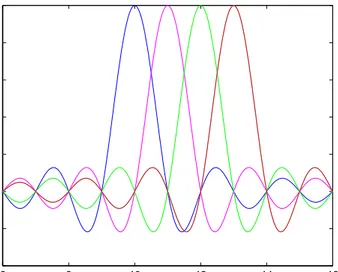
Using OFDM the channel is converted into a number of overlapping but mutu-ally orthogonal subchannels in the frequency domain which do not interfere with each other. Therefore simultaneous transmission is possible without intercarrier interference (ICI). The subcarriers must overlap to ensure high spectral efficiency and it is still possible to recover the individual subcarriers despite their overlap-ping spectrum provided that the orthogonality is maintained. The orthogonality is achieved by making use of fast Fourier transform (FFT) algorithm. In the frequency domain, the subcarriers have a sinc pulse shape such that the main lobe of each subcarrier lies on the nulls of all other subcarriers thereby avoiding ICI. The frequency spectrum of an OFDM signal with 1 MHz subcarrier spacing is shown in Figure 3.1. 6 8 10 12 14 16 −0.4 −0.2 0 0.2 0.4 0.6 0.8 1 Frequency (MHz) Subcarrier Spectrum
OFDM can be easily implemented by using the FFT algorithm. At the trans-mitter an OFDM system treats the source symbols as though they were in the frequency domain and feeds the symbols to an inverse fast Fourier transform (IFFT) block which brings the signal into the time domain and modulates the data onto orthogonal subcarriers. Let N be the number of carriers available in the OFDM system and one PSK or QAM symbol is transmitted per subcarrier. The OFDM symbol is the superposition of N subcarriers spaced ∆f = 1/T0 Hz
apart where T0 is the OFDM symbol duration. The time domain OFDM symbol
is given as, qn = 1 √ N N −1X k=0 ske j2πkn N , n = 0, ..., N − 1, (3.1)
where it can be seen that the symbol sk modulates a complex sinusoid. Note that the scaling factor 1/√N is included so that the average power of qn’s equals that of sk’s.
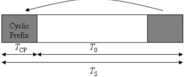
After the IFFT operation, a cyclic prefix (CP) is added to the beginning of each OFDM symbol which is transmitted before the actual OFDM symbol itself. CP is a copy of the last part of the OFDM symbol, and it extends the length of the transmitted signal and guards the symbol by being interfered from delayed copies of the previous symbols. The CP is illustrated in Figure 3.2. The total duration of the symbol can be written as TS = T0+ TCP, where TS is the total duration of the transmitted symbol, T0 is the duration of the OFDM symbol
after IFFT operation and TCP is the duration of the CP.
Figure 3.2: Addition of the cyclic prefix to an OFDM symbol.
The length of the CP should be greater than the maximum excess delay of the multipath channel. The CP is removed at the receiver and different subcarriers can be separated by passing them through an FFT block, therefore bringing them back to the frequency domain. Due to the CP, the linear convolution of the
channel impulse response with the transmitted data becomes a cyclic convolution. Due to the properties of cyclic convolution, the effect of the multipath channel is converted to a pointwise multiplication of the transmitted data symbols by the channel transfer function. Therefore by using CP, ISI is completely eliminated from the system.
When there is high mobility, i.e., high Doppler spread in the system such that the channel becomes a time-variant channel, the variations disrupt the orthogo-nality of the subcarriers and cause ICI. In those cases, a more complex system is needed to model such behavior. The effects of mobility on system performance will be investigated in Section 3.5. For low mobility cases when there exists insignificant Doppler spread, ICI may be ignored.
OFDM can be easily utilized for multiple access purposes. Orthogonal Fre-quency Division Multiple Access (OFDMA) is based on OFDM and it is imple-mented by dividing the total bandwidth into a number of subchannels consisting of a set of subcarriers. Users may occupy one or more than one subchannel, depending on their quality of service (QoS) requirements and the system load-ing characteristics. There are two strategies for allocatload-ing subcarrier groups to users. The first strategy groups adjacent subcarriers in the same frequency range in each subchannel. In the second one, the subchannels are spread over the to-tal bandwidth. These subchannelization schemes will be further discussed in Section 3.3.
3.2
MIMO-OFDM
In a MIMO-OFDM system, the MIMO channels on each subcarrier can be mod-eled similar to the MIMO channel for single carrier systems except that now the channel is frequency selective with L distinct paths. From Chapter 2, (2.1) can be extended to a MIMO system with MT transmit and MR receive antennas. For simplicity it is assumed that the channel is time-invariant for the duration of one OFDM symbol but may change from symbol to symbol. This change may be the result of mobility present in the channel and the channel variations with respect to OFDM symbol index u may be rapid or slow depending on the mobil-ity. The channel impulse response from transmit antenna j to receive antenna i,
at OFDM symbol index u can be expressed as huij(τ ) = L−1 X l=0 αuij(l)δ(τ − τl), (3.2) where αu
ij(l) is the complex amplitude of the lth path from transmit antenna j to receive antenna i with time delay τl. It should be noted that the αuij(l)’s describe the small-scale fading in the channel therefore path loss and log normal shadowing effects are ignored. The αu
ij(l)’s are zero-mean, complex Gaussian random variables which are independent for any (i, j, l, u). It is also assumed that the path gains between any transmit and receive antenna pair follow the same power delay profile such that E[|αu
ij(l)|2] = βl2 for all (i, j, l, u). The powers of the L paths are normalized such that L−1P
l=0 β2
l = 1. This normalization is important because it ensures that the received power at each receive antenna is equal to total transmitted power.
The frequency response of the channel for the kth subcarrier during the uth
OFDM symbol is ˜ Hiju(k) = L−1 X l=0 αuij(l)e−j2πk∆f τl, (3.3) = L−1 X l=0 αu ij(l)e−j2πkl/N. (3.4)
Using this we can express the received signal after CP removal and FFT opera-tions by noting that due to the use of the CP, the received signal is the pointwise multiplication of the transmitted symbols by the channel frequency response. The received signal at receive antenna i on the kth subcarrier at OFDM symbol
index u is given by yui(k) = √1 MT MT X j=1 ˜ Hiju(k)suj(k) + vi(k), (3.5)
where vi(k) is the additive complex Gaussian noise which is assumed to be i.i.d. circularly symmetric with variance N0/2 per dimension. It should be noted that
the noise process, n, acting on the original received signal before CP removal and FFT operations, becomes the noise process v after CP removal and FFT. There-fore the noise process v is basically the FFT of the noise process n. However,
due to the special structure of the FFT matrix, the distribution of the noise pro-cesses are the same [14]. The √1
MT factor is included so that the total transmitted power is constrained to 1, regardless of the number of transmit antennas MT. It is assumed that the signals transmitted from individual antenna elements have equal powers of √1
MT such that the transmit power is distributed equally across all antennas.
3.3
IEEE 802.16 PHY Layer
The IEEE 802.16 standard is considered as a solution for future wireless broad-band communications that offer high data rates, more scalability, broader cov-erage. Worldwide Interoperability for Microwave Access, known as WiMAX, is a wireless networking standard which aims to provide conformance and interop-erability across IEEE 802.16 standard based products. In this section we will review the physical (PHY) layer of the IEEE 802.16 standard which will serve as the basis of our simulations. Several other amendments are still under de-velopment addressing issues such as advanced air interface [41] and we will also consider some new techniques put forth in this amendment. For the rest of this thesis, the term WiMAX and IEEE 802.16 will be used interchangeably.
The IEEE 802.16 standard is a family of standards. The latest IEEE 802.16e-2005 is an evolution from the IEEE 802.16d-2004 standard which merged and revised all the earlier versions of the standard. We will use the configurations specified in IEEE 802.16e in the rest of this work. The IEEE 802.16e air interface adopts OFDMA for improved multipath performance in non-line-of-sight (NLOS) environments. Scalable OFDMA is also introduced to support scalable channel bandwidths from 1.25 to 20 MHz which allows the data rate to scale easily by choosing a different FFT size based on the available channel bandwidth.
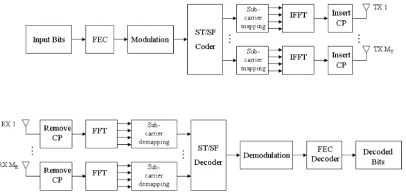
The PHY layer includes forward error correction (FEC), constellation map-ping (modulation), ST coding, subcarrier permutation and OFDM on the trans-mitter side and recovery operations on the receiver side that are the reverse of the operations carried out at the transmitter. A block diagram of the WiMAX PHY layer is shown in Figure 3.3. The receiver also includes channel estima-tion and carrier frequency synchronizaestima-tion blocks which are omitted here since throughout this work perfect channel estimation and synchronization is assumed. Furthermore, we will be studying the downlink only.
Figure 3.3: Block diagram of WiMAX PHY layer.
The data bits are first passed through a FEC block which consists of chan-nel coding and interleaving. Chanchan-nel coding is the process of adding redundant information bits into a data block for error-detection and correction purposes, where the amount of redundancy will determine the robustness of the trans-mission to impairments. Several different encoding schemes are present in the standard however we will consider convolutional codes (CC) and convolutional turbo codes (CTC) in this thesis.
Interleaving is a deterministic process which changes the order of transmitted bits. It is used to prevent long error bursts and therefore reduce the error con-centration to be corrected. For OFDM systems, this means that bits that were adjacent in time are transmitted on subcarriers that are spaced out in frequency. In WiMAX, interleaving is done through a two stage permutation, the first is to avoid mapping adjacent coded bits on adjacent sub-carriers and the second permutation insures that adjacent coded bits are mapped alternately onto less or more significant bits of the constellation, thus avoiding long runs of unreliable bits.
Once the signal has been FEC coded, it enters the modulation block where the bits are Gray coded into symbols. To achieve equal average symbol energy, the constellations are normalized by multiplying all of its points by an appropriate factor. The next stage is ST or SF coding. Some of the schemes considered for this block will be discussed in detail in Sections 3.3.1 and 3.4.
After this, the next step is subchannelization. In OFDMA, the resource allo-cated to a user is called a subchannel. The formation of subchannels differ based on the permutation scheme in use. Here we will consider two subchanneliza-tion schemes. The first one is partial usage of subcarriers (PUSC) which assigns subcarriers that are distributed across the bandwidth to each subchannel. The second one is called band AMC and this scheme assigns contiguous subcarriers to each subchannel.
In PUSC the symbols are grouped together into slots, slots are grouped into clusters, pilot positions are determined, clusters are grouped into groups and subchannels are formed out of these groups. The end result is a burst unit which is several subcarriers wide and several symbols long and the subcarriers are not necessarily contiguous to each other. The pilot subcarriers are embedded in be-tween the data subcarriers to provide channel state information (CSI) at the receiver. Regardless of the subchannelization scheme, guard subcarriers which are set to null are placed at the start and end of each symbol. The other subcar-rier permutation scheme considered here is band AMC, in which subchannels are composed of adjacent subcarriers. Although OFDMA is intended for multiple users to be scheduled on the subchannels, we analyze the case where a single user occupies all available subchannels. This simplifying assumption is made so that we can better analyze the effects of other parameters, such as FEC coding or space-time coding, on the performance of the WiMAX PHY layer.
After the completion of these steps, the resulting signal is fed to the OFDM modulator and is ready to be transmitted through the MT transmit antennas. At the receiver the reverse operations are applied to decode the signal.
In WiMAX, there is a mechanism which adjusts modulation and coding pa-rameters dynamically to maximize throughput and minimize bit error rate (BER) in the face of changing channel conditions which is called adaptive modulation and coding (AMC). The FEC profiles are paired with several modulation schemes to form burst profiles of varying robustness and efficiency. There are different block size and code rate options for the different modulation types. The users report their current channel condition to the BS and based on this feedback, a coding profile is selected for the downlink data transmissions. Thus, users who experience poor channel conditions, i.e., low SNR, at a given time, will be pro-vided with better error correction than those users experiencing better channel conditions at the same time. In Section 3.5 we will analyze the performance of the WiMAX PHY layer for some of these FEC profiles.
3.3.1
MIMO Techniques in IEEE 802.16
The IEEE 802.16 standard defines some MIMO techniques in order to achieve transmit diversity and/or higher spectral efficiency. Although they are present in the 802.16e-2005 standard as optional features, it is clear that these techniques are essential for achieving the performance requirements since they can enhance transmission speed and/or reception quality of the signals. That’s why WiMAX Forum has specified the Alamouti ST code and SM as two mandatory profiles for the downlink.
For MT = 2 there are three MIMO techniques. They include the Alamouti ST code, SM and a variant of the Golden code which incorporates the benefits of ST codes and SM. The space-time code given in the standard is the Alamouti code, referred to as Matrix A, and is given below. This code has a rate of 1 symbol/pcu. We will refer to this code as space-time Alamouti (ST-Alamouti) to avoid confusion with the code which will be presented in Section 3.4.
A = " s1 −s∗2 s2 s∗1 # , (3.6)
where the row index indicates the transmit antenna number and column index indicates the OFDM symbol. Here si contains only data symbols. Before OFDM transmission occurs, depending on the subchannelization scheme these data sub-carriers will undergo a permutation scheme and the null and pilot subsub-carriers will be placed amongst the data subcarriers. Let ncarr be the number of data subcarriers in an OFDM symbol. We can express the data symbols within Matrix A as A = " (s1 s3. . . s2ncarr−1) −(s∗2 s∗4. . . s∗2ncarr) (s2 s4. . . s2ncarr) (s∗1 s∗3. . . s∗2ncarr−1) # , (3.7)
where the data symbols will be input to the subcarrier mapping block, where if PUSC is used as the subcarrier mapping scheme they will be reordered and distributed across the OFDM symbol. If AMC is used they will be mapped contiguously. After mapping has taken place, pilot subcarriers will be inserted among the data subcarriers and guard subcarriers will be placed at the beginning and end of the OFDM symbol. These steps will be carried out for all of the ST code and SM matrices given below.
The other ST code is Matrix C which is a variant of the Golden code presented in [10]. This code has a decoding complexity of |M|4 for M-ary data symbols.