MODELLING of VISIBLE LIGHT CHANNELS and PERFORMANCE
ANALYSIS FOR OPTICAL OFDM SYSTEMS
Hüseyin Fuat Alsan
2 eyi n F ua t A lsa n M .S . T he sis 2016 S tude nt ’s F ul l N am e P h.D . (or M .S . or M .A .) T he sis 20 11
by
Huseyin Fuat ALSAN
Bachelor’s degree, Electronics Engineering, Kadir Has University, 2013
Submitted to the Institute for Graduate Studies in Science and Engineering in partial fulfillment of
the requirements for the degree of Master of Science
Graduate Program in FBE Program for which the Thesis is Submitted Kadir Has University
Abstract
Modelling of Visible Light Channels and Performance Analysis for
Optical OFDM Systems
This work is concerned with a challenging problem of modeling and simulation of vis-ible light communications (VLC) channels for optical wireless communication (OWC) sys-tems. A proper channel model for VLC is absent in the current literature. For this reason, two different indoor channel model with different material types and different receiver-transmitter locations have been obtained and implemented for asymmetrically clipped optical orthogonal frequency division multiplexing (ACO-OFDM) technique. The channel models have been obtained from optical and illumination design software Zemax®by using sequential and non-sequential ray-tracing capabilities for VLC spectrum. The results of implementation of the realistic channel model has significant diversity from Gaussian and infra-red (IR) channel models implemented in studies.
ÖZET
Görünür Işıkla Haberleşme İçı̇n Gerçekcı̇ Kanal Modellenmesİ ve
Optı̇k Sı̇stemler İçı̇n Performans Analı̇zı̇
Bu çalışma, görünür ışıkla haberleşmeyi (VLC), optik kablosuz haberleşme (OWC) sistemleri için simüle etmektedir ve kanal modellemede karşılaşılan zorlu bir sorunu göze alır. Görünür ışıkla haberleşme için gerçekci bir kanal modeli henüz litaretürde bulunma-maktadır. Bu eksiklikten dolayı farklı malzeme tipleri ve farklı alıcı - verici yerleri ile iki farklı kapalı alan kanal modeli elde edilmiş ve asimetrik kesilmiş optik dik frekans bölmeli çoklama (ACO-OFDM) teknigi için uygulanmıstır. Kanal modelleri, VLC spektrumu işin sıralı (sequential) ve sıralı olmayan (non-sequential) ısın izleme yeteneklerini ile optik ve aydınlanma tasarım yazılımı olan Zemax® ile elde edilmiştir. Gercekci kanal modelinin uygulanması sonucu Gauss (Gaussian) ve kızıl ötesi (infra-red, IR) kanal modeli uygulanan çalışmalara nazaran önemli çeşitlilikler içermektedir.
ACKNOWLEDGEMENTS
I deeply thank my thesis supervisor, Prof. Dr. Erdal Panayırcı who has supported me, not only for the project, but also for every step of my graduate studies. His suggestions and positive criticism were invaluable during my education and thesis study. Also, I thank the other professors and my graduate assistant friends. They always welcomed me with a big smile, and helped me plan my graduate studies. Their appreciation of my work helped me go through this thesis.
I would like to acknowledge both the Department of Electronics Engineering of Kadir Has University, Department of Electronics Engineering and Prof. Dr. Erdal Panayırcı’s re-search grant from the TUBITAK-COST for providing me financial support throughout my graduate studies. I have been a graduate assistant at the Department of Electronics Engineer-ing and a research assistant in Prof. Panayırcı’s project in the last two years. In addition, I would like to thank TUBITAK-COST for providing me financial support throughout my graduate studies.
Contents
Abstract . . . i
ÖZET . . . ii
ACKNOWLEDGEMENTS . . . iii
List of Figures . . . vi
List of Tables . . . vii
LIST OF SYMBOLS/ABBREVIATIONS . . . viii
1. INTRODUCTION . . . 1
1.1. Motivation and Main Contribution of This Work . . . 3
2. OPTICAL SOURCES and DETECTORS . . . 4
2.1. Sources . . . 4
2.2. Light Emitting Diode . . . 4
2.2.1. LED Modulation Bandwidth . . . 5
2.3. LED Line of Sight Propagation . . . 6
2.4. Laser Operation and Laser Diodes . . . 7
2.4.1. Laser Operetion . . . 8
2.5. Photodetectors . . . 8
3. CHANNEL MODELING . . . 11
3.1. Visible Light Communication Channel Modeling . . . 11
3.1.1. Channel Modelling Methodology . . . 12
3.2. Channel Impulse Response for an Empty Room . . . 12
3.3. Different Configurations and Their Channel Impulse Response . . . 14
3.3.1. Channel Impulse Response . . . 14
4. MODULATION TECHNIQUES USED IN VLC . . . 21
4.1. OFDM Based Modulation Techniques . . . 21
4.2. OFDM FOR OPTICAL WIRELESS COMMUNICATION . . . 22
4.2.1. ACO-OFDM . . . 23
4.2.2. DCO-OFDM . . . 25
5. VLC SYSTEM DESING . . . 29
5.2. Detection Noise and SNR . . . 29
5.2.1. Noise Sources . . . 29
5.2.2. SNR Definition . . . 31
5.3. Simulation Results . . . 31
6. CONCLUSIONS and FUTURE RESEARCH . . . 35
6.1. Conclusions . . . 35
6.2. Future Research . . . 35
List of Figures
Figure 1.1. LOS Configurations [19] . . . 3
Figure 3.1. Spectral Power Distribution of Cree Xlamp® MC-E White LED [18] . 13 Figure 3.2. Steps of the Zemax® procedure [18] . . . . 13
Figure 3.3. Empty room and reflections [18] . . . 14
Figure 3.4. Empty room channel impulse response (reflections are ignored) [18] . 15 Figure 3.5. Empty room channel impulse response (with first order reflections) [18] 17 Figure 3.6. Comparison of channel impulse response for different order of reflec-tions [18] . . . 18
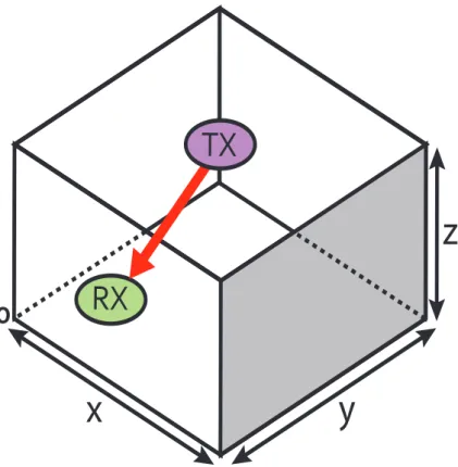
Figure 3.7. Structure and Channel Impulse Response of Configuration A . . . 19
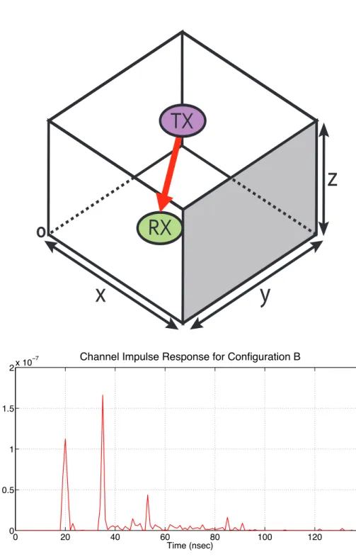
Figure 3.8. Structure and Channel Impulse Response of Configuration B . . . 20
Figure 4.1. ACO Block Diagram . . . 23
Figure 4.2. DCO Block Diagram . . . 26
Figure 5.1. BER performance of Configuration A . . . 33
List of Tables
LIST OF SYMBOLS/ABBREVIATIONS
ACO− OF DM : Asymmetrically Clipped Optical OFDM AW GN : Additive White Gaussian Noise
A/D : Analog To Digital Converter
A(λ) : Spectral Radiance of Sun
BW : Bandwidth of Photodetector Device
c : Speed of Light
CIR : Channel Impulse Response
CP : Cyclic Prefix
DCO− OF DM : DC Biased Optical OFDM
Eb : Energy per Bit
Eb,opt,ACO : Optical Energy per Bit for ACO
Eb,elec,ACO : Electrical Energy per Bit for ACO
F F T : Fast Fourier Transform
IF F T : Inverse Fast Fourier Transform
F OV : Field of View
g(ζ) : Photodetector Transfer Function
H0 : Channel DC Gain
h : Planck’s Constant
IR : Infra-Red
ln : Lambertian Directivity Number
Ip : Current Generated by Photodetector
Isky : Irradiance for Sky
Isun : Irradiance for Sun
ISI : Inter-Symbol Interference
K : Boltzmann’s Constant
N : Number of Subcarriers
Ncp : Length of Cyclic Prefix
LEDi : Light Emitting Diode
LOS : Line of Sight
F OS : Free Space Optics
i : Current Generated by Photodetector Pr : Optical Power of Detected Light
Pi : Power of ithRay
R : Reflection Coefficient
Rload : Load Impedance
Mr(θ) : Photodetector Effective Area M IM O : Multiple Input Multiple Output
M − QAM : M-ary Quadrature Amplitude Modulation OF DM : Orthogonal Frequency Multiplexing
V LC : Visible Light Communication
OW C : Optical Wireless Communication
O− OF DM : Optical OFDM
N EP : Noise Equivalent Power
N : Number of Rays Received in the Detector
S(λ) : Spectral Radiance of Sky
SN R : Signal to Noise Ratio
SN Roptical : Optical Signal to Noise Ratio
q : Electronic charge
QP SK : Quadrature Phase Shift Keying
QAM : Quadrature Amplitude Modulation
tlos : Line of Sight Path Delay
T : Temperature of Photodetector Devce
Tsym :Symbol Duration
ZF :Zero Forcing
τi : Propagation time of ithRay
τ0 : Mean Excess Delay
τRM S : RMS Delay Spread
θ : Angle of Maximum Power
γm : SNR
δ : Wavelength
η : Efficiency of Photodetector
ξ : Fraction of Electron-hole Pairs
α : Absorption Coefficient
ζ : Photodetector Area
δ(.) : Dirac delta function
σ2
pf : Photon Fluctuation Noise Power
σ2
dcex : Dark Current and Excess Noise Power σ2
br : Background Radiation Power
σ2
ther : Thermal Noise Variance Power σ2
total : Total Noise Power
1. INTRODUCTION
Since the introduction of mobile communications, demand for high data rates are grow-ing rapidly. Therefore, in each generation of mobile technologies, faster and better systems are required. To satisfy this demand, more bandwidth in each generation is required. On the contrary, bandwidth is highly populated and regulated in traditional radio frequency (RF) communications systems. This makes spectrum a very scarce resource. To address this issue, communication engineers are researching better alternatives to traditional RF communica-tions. Some examples are: cognitive radio, femtocell communication systems etc... One of the promising alternative is the visible light communication (VLC).
VLC has numerous advantages over traditional RF communications. The most impor-tant one is the spectrum. Unlike traditional RF communication system, VLC spectrum is unpopulated and unregulated. This advantage can easily address the spectrum issue of the traditional RF communication systems. VLC is also more secure than traditional RF commu-nications systems since commucommu-nications signal cannot penetrate walls and reduces the risk of man in the middle attacks.
One of the major advantages that visible light communication can offer is that a VLC system can be used both for illumination and communication. Considering the case that a household with light emitting diodes. These light emitting diodes can easily replace any light bump and fluorescent lamb (see chapter 2 for details). They can also be used as transmitter device for visible light communication systems. Light emitting diodes also have longer lifes-pan, high tolerance to humidity, relatively low power consumption and relatively less heat generation. If light emitting diodes turned on/off fast enough, human eye won’t notice the effect and see it as if a constantly on light source. This makes visible light communication since higher data rate will not disturb the human eyes.
The most common and practical scenario for visible light communication is short link indoor room environment. In these short links, intensity of the light rays emitted from light emitting diodes can be modulated to carry information and a photodetector can be used to
convert light intensity to information (see chapter 4 for details). Another option for visible light communication is the laser diodes but they’re far less practical as a household illumi-nation purpose.
Overall advantages of visible light communication are,
1. Unregulated and wide bandwidth (200 THz in 700 - 1500 nm range) 2. Healthy (no RF radation)
3. Low power consumption (LEDs are very efficient in terms of energy)
4. Security (Light rays do not pass through walls, making the communication isolated) 5. Small and relatively cheap components
6. Immunity to the electromagnetic interference
Visible light communication comes in four main configurations as you can see in the figure 1.1,
1. Directed Line of Sight (a) 2. Non-directed Line of Sight (b) 3. Diffuse (c)
4. Tracked (d)
This document is organised as follows
• Chapter 2 will explain characteristics of sources and detectors and how they work • Chapter 3 will explain how realistic visible light communication channels are modelled • Chapter 4 will consider all modulation techniques that can be used in visible light
com-munication.
• Chapter 5 is about building visible light communication system from top to bottom. • Finally, chapter 6 will conclude this research and talk about what can be done in future.
Figure 1.1. LOS Configurations [19]
1.1. Motivation and Main Contribution of This Work
Current literature in visible light communication only considers channels with additive white gaussian noise and all simulations and comparisons are done with respect to additive white gaussian channel only. However, in a practical and more realistic scenario we would need to use a proper channel model. This work is trying to fill this deficiency by introduc-ing a new and realistic channel model. Channel model is calculated usintroduc-ing Zemax®, a ray tracing optical simulation software. This new channel model is then used for simulating ACO-OFDM and DCO-OFDM modulated systems. Results are shown in section 5.
2. OPTICAL SOURCES and DETECTORS
2.1. Sources
There are two common light sources in optical wireless communication systems: light emitting diodes (LEDs), laser diode (LDs). Their usability depends on the environment (and application requirement, of course). LEDs can also be used as a illumination device thus, making them more appropriate for short indoor communication links. LDs’ highly directional beam profile makes them more suitable for long range outdoor applications. This section discusses their structure and optical characteristics.
2.2. Light Emitting Diode
Light emitting diodes (or LEDs) is a semiconductor p-n junction device with photon emission capability. LEDs can be forward biased for active operation which makes them very similar to common p-n junction semiconductor diodes. LEDs generate light with a process called ”radiative recombination”, in which the exited electrons return to valence band and give away energy as photons. These photons perceived as light by human eye.
LEDs, are state of the art illumination devices that can be used almost anywhere from TVs to household lightning. Their small size, low forward voltage & drive current and su-perior brightness in the visible spectrum makes them ideal replacement for traditional fluo-rescent lamps and light bulbs. LEDs can be fabricated to emit a specific wavelength. The wavelength of LED determines the emission colour. Some colours (wavelengths) can be more applicable for certain scenario. For example: green colour commonly used in under-water OWC due to low attenuation in this band and infrared (IR) is a common choice for TV remotes. However, in visible light communication, visible spectrum of light is obviously pre-ferred (with white LEDs being a common choice). The relation between energy, frequency and wavelength of photon is given below.
E = E2− E1 = hf = hc
where, E1 and E2 are energies of states, h = 6.626 × 10⁻³⁴Js is the Planck’s constant, f is the frequency, c = 3 × 10⁸m/s speed of the light and λ is the wavelength of the emitted light.
LEDs generate light by transitioning an electron from excited state to a lower energy state. This transition leads to emission of photons which we perceive as light. This phenom-ena is called radiative recombination and can be summarised as below.
1. An electron is exited to move from valence band to conduction band. Its energy is shifted from E1 to E2.
2. Exited electron spontaneously return from conduction band to valence band and gives away its excess energy (E2− E1) as a photon.
3. The released photons are perceived as light.
An important notice here is that when photons radiation from radiative recombination occurs randomly thus there is no correlation between different radiated photons. This ran-domness makes LEDs a incoherent light source.
2.2.1. LED Modulation Bandwidth
Light emitting diode is a crucial part of a visible communication system. Light emitting diode performance is a key parameter in overall system performance. The most important pa-rameter of LED is the bandwidth since higher data rates require more bandwidth. Therefore, LED bandwidth should be investigated. LED frequency response and modulation bandwidth is related to followings:
1. The induced current 2. p-n junction capacitance 3. Parasitic capacitance
It is important to note that capacitance values are less effective when current flow is increased. So for higher data rates, when more bandwidth is required, it is practical to impose
a DC constant current over modulating AC current to increase bandwidth. We would need to use a DC biasing current for illumination purposes anyway so this method is actually desired. If the DC power is given as Pdc and that at frequency, ω, by P (ω), then the relative optical power output at any given frequency is given as [10]
P (ω) Pdc
= ! 1
1 + (ωτ )2 (2.2)
where τ is the minority carrier lifetime.
Another important factor in LED modulation bandwidth is the minority carrier life-time. If modulation bandwidth is desired to be increased, than carrier lifetime should be limited to minimum. Minority carrier lifetime can be reduced by increasing the doping level in recombination region.
2.3. LED Line of Sight Propagation
Line of sight (LOS) propagation of LEDs can be modelled as a Lambertian source. A Lambertian source distribution is given below:
K0(θ) = ⎧ ⎨ ⎩ l1+1 2π cos l1(θ) f or θ ∈ [−π/2, π/2] 0 f or θ≥ π/2
where l1is the Lambert’s number for directivity of LED rays, θ = 0 is the angle of maximum radiated power. Directiviity number l1 can be expressed as follows:
l1 = −ln2 ln(cos(θ1/2))
where θ1/2 is the angle which power is half. Radiated beam intensity is given as below:
L(θ) = Pi l1+ 1
2π cos(θ1/2) (2.4)
We can model photodetector devices in similar fashion. Effective detection area of a photo-conductor is given as follows:
Mr(θ) = ⎧ ⎨ ⎩ Mrcos(θ) f or 0≤ ζ ≤ π/2 0 f or θ≥ π/2
where ζ is the area of the photodetector and Mr(θ) is the effective area. In short range LOS links channel impulse response can be written as:
hlos(t) =
Mr(l1+ 1) 2πd2 cos
l1(θ)g(ζ)cos(ζ)δ(t− t
los) (2.5)
where g(ζ) is the transfer function of photodetector, δ is the dirac delta function, tlos is the LOS path delay. With given speed of light c and distance between LED and photodetector d, tloscan be written as tlos = dc therefore, channel impulse response equation can be rewritten as below. hlos(t) = Mr(l1+ 1) 2πd2 cos l1(θ)g(ζ)cos(ζ)δ(t−d c) (2.6)
2.4. Laser Operation and Laser Diodes
Light amplification by stimulated emitted radiation (Laser) is another option for visible light communication. Laser spectrum is in the visible light domain but rarely used for indoor applications. They’re primarily used for outdoor free space optics (FSO) channels where they’re chances of fighting the air turbulence is higher than LEDs. As they’re name sug-gest, they amplify the light that is generated. This amplification factor allows them to reach much higher distances than LEDs, making them more suitable for long distance
communi-cation systems. Choice of laser, wavelength and bandwidth will be function of atmospheric propagtion conditions, optical background noise.
2.4.1. Laser Operetion
Lasers’ light emission is similar to LEDs, however, they have a distinct difference: co-herence. Lasers generate light through a process called ”stimulated emission”. In stimulated emission, two levels of atomic energy is considered, E1and E2. Just like in LED, upper level of energy E2 can fall back to lower level of energy E1. However for laser case, an external stimulus energy Ep = hv = hc/λ is applied via an exciting photon. This forces emitted photon to be the same phase and frequency as exciting photon, thus making laser a coherent light source.
2.5. Photodetectors
Photodetectors are transducer devices which converts light intensity to electrical cur-rent (signal). They are modelled as a curcur-rent source hence and transimpedence (curcur-rent in, voltage out) amplifier is required to amplify the received weak signal. Efficiency (η) of a photodetector is defined by,
η = Electronsout
P hotonsinput (2.7)
η = (1− R)ξ(1 − e−αd)
where R is the reflection coefficient, ξ is the fraction of electron-hole pairs, α is the absorption coefficient and d is the distance. There are two important things that should be
also considered:
1. Dark current - Dark current is basically the current when the absence of light. Dark current determines the minimum detectable since a signal. Dark current is a function of operating temperature, bias voltage and detector itself.
2. Noise-equivalent power - Noise equivalent power (NEP) is a measure of minimum op-tical signal to generate current. NEP is a concise measure explains the relation between optical power and noise. It is mathematically defined as follows:
i = ξqeqλPr
hc = RPr (2.8)
where i is the current generated by photodetector, Pr is the optical power of detected light, q is the electronic charge, R is the photodetector responsivity. Also responsivity R can be defined as:
R = λqξqe hc =
λ
1.24ξqe (2.9)
bandwidth of photodetector is function of followings: 1. Photodetector’s internal capacitance.
2. Diffusion of carriers generated outside the depletion region. 3. Depletion region carrier transit time.
In conclusion, an ideal photodetector should meet the creterion below:
1. Lowest dark current and NEP possible: so that smaller signals can be detected. 2. Fast response time for high data rate applications.
3. Low cost, smaller dimensions and high durability.
1. PIN 2. APD
3. Photoconductors
4. Metal-Semiconductor metal
3. CHANNEL MODELING
3.1. Visible Light Communication Channel Modeling
Despite the growing academic and industrial interest along with the related literature on visible light communications(VLC), there is a lack of proper channel model for optical wireless communications (OWC) yet. Current academic literature has been using mainly two different channel models. Many previous academic works considered only AWGN and sin-gle tap channel model. Another convention in recent academic works are based on infra-red (IR) channel and AWGN for the performance evaluation without solid justification[1]-[3]. Since the VLC uses a wide spectrum between 380 nm - 700 nm, the conventional narrow-band model for infra-red spectrum may not be applied to VLC systems properly. All of these problems necessitates the development of realistic VLC channel models. In this pa-per,software aided realistic indoor VLC channel model is developed and simulated for two major O-OFDM systems namely ACO-OFDM and DCO-OFDM. Also, channel impulse re-sponses (CIR’s) and channel parameters for two different scenerios has been taken and imple-mented to O-OFDM systems to observe performance aspect of the realistic channel model.
Our study is based on Zemax®which is an optical and illumination design software with sequential and non-sequential ray-tracing capabilities [11]. It allows accurate description of the interaction of rays emitted from the LED’s for a user defined environment. In non-sequential ray-tracing, rays are traced along a physically realizable path until they intercept an object. The line-of-sight (LOS) response depends to the LOS distance. Besides the LOS component there is a large number of reflections from the ceiling, walls, floor and as well as objects within the environment. The rays that reflected also received by very sensitive photo detectors. The simulation environments and scenarios are created in Zemax®is then used to simulate O-OFDM systems (ACO-OFDM and DCO-OFDM)
3.1.1. Channel Modelling Methodology
First, an environment which the communication occur must be created and modelled. For indoor visible light communication purposes, a rectangular, three dimensional room can be used. Room can be empty but for a more realistic modelling, some furniture should be taken into account. Also, reflectance of the surface materials effects reflected rays that hit that surface therefore, reflectance should be taken into account too. Briefly, parameters of a channel impulse response are given below.
1. Room dimensions
2. Surface material reflectance 3. Furniture surface reflectance 4. Furniture positions
5. Transmitter and receiver positions
After all parameters are set, computer aided design tools can be used to generate channel impulse response. There are several computer aided design software that can be used. In this study, Zemax® as mentioned. It is also important that spectral properties of LEDs. In figure 3.1.1, Cree Xlamp MC-E White LED spectral power distribution is given.
3.2. Channel Impulse Response for an Empty Room
An empty room can be constructed by rectangle prism. A rectangle prism is basically a three dimensional hyper rectangle with a height, width and depth. Empty room is the simplest scenario that can be used and forms a basis for more complex scenarios. More complex scenarios include additional light sources and furniture. After room geometry and objects in the room is set up, non-sequtial ray tracing ability of Zemax® can be used to calculate channel impulse response. Figure 3.2 illustrates the procedure for obtaining channel impulse response and parameters.
Channel impulse response is composed of a line of sight component with large number of reflected components. Reflected components are the light rays that bounce off ceiling,
Figure 3.1. Spectral Power Distribution of Cree Xlamp® MC-E White LED [18]
Figure 3.2. Steps of the Zemax®procedure [18]
walls, floor and other objects in the room. Line of sight component and all the reflected components are detected by photodetector if they fit in the detector surface. Components that are outside the surface cannot be detected but they can bounce off from another object and eventually reach the detector surface. Figure 3.3 illustrates the three dimensional rectangular empty room. After Zemax® is done calculating, it will generate an output file which then can be used in MATLAB to simulate a communication system. In figure 3.4 channel impulse response of an empty room is given and in figure 3.5 channel impulse response for first order reflections is given. In figure 3.6, channel impulse responses for different orders are compared in a single figure.
Figure 3.3. Empty room and reflections [18]
3.3. Different Configurations and Their Channel Impulse Response
Multi transmitter effects This will increase multi-path dispersion since more
reflec-tions path components are added. The RMS delay spread is increased.
Position/rotation of LED/Photodetector Position and rotation of LED and
photode-tector can significantly change channel parameters since it directly effects scattering.
Surface Materials Effects Surface materials effects depends on their reflectance. If
reflectance is high, receiver receives more scattering component thus increases RMS delay spread. If reflectance is low then, receiver receives less scattering component thus decreases RMS delay spread.
3.3.1. Channel Impulse Response
Figure 3.4. Empty room channel impulse response (reflections are ignored) [18] h(t) = N % i=1 Piδ(t− τi) (3.1)
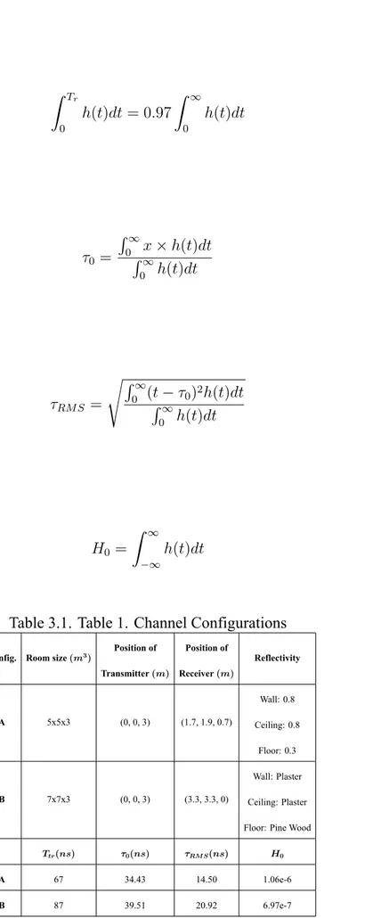
where Pi is the power of the ith ray, τi is the propagation time of the ith ray,δ is the ”Dirac delta” function and N is the number of rays received in the detector. Based on obtained CIR’s, we can further quantify the fundamental channel characteristics. Channel DC gain (H0) is one of the most important feature of the VLC channel. It determines the achievable signal-to-noise ratio (SNR) for fixed transmitter power. The delay profile is composed of dominant multiple LOS links and less number of NLOS delay taps. The temporal dispersion of a power delay profile can be expressed by the mean excess delay (τ0) and the channel root-mean-square (RMS) delay spread (τRM S).[12]-[13]These parameters are given by,
& Tr 0 h(t)dt = 0.97 & ∞ 0 h(t)dt (3.2) τ0 = '∞ 0'x× h(t)dt ∞ 0 h(t)dt (3.3) τRM S = ('∞ 0 (t'− τ0)2h(t)dt ∞ 0 h(t)dt (3.4) H0 = & ∞ −∞ h(t)dt (3.5)
Table 3.1. Table 1. Channel Configurations
Config. Room size (m3) Position of
Transmitter (m) Position of Receiver (m) Reflectivity A 5x5x3 (0, 0, 3) (1.7, 1.9, 0.7) Wall: 0.8 Ceiling: 0.8 Floor: 0.3 B 7x7x3 (0, 0, 3) (3.3, 3.3, 0) Wall: Plaster Ceiling: Plaster Floor: Pine Wood
Ttr(ns) τ0(ns) τRM S(ns) H0
A 67 34.43 14.50 1.06e-6
RX
TX
O
x
y
z
0 10 20 30 40 50 60 70 80 90 0 0.5 1 1.5x 10⁻⁷ Channel Impulse Response for Configuration A
Time (nsec)
Power (Watts)
RX
TX
O
x
y
z
0 20 40 60 80 100 120 140 0 0.5 1 1.5 2x 10⁻⁷ Channel Impulse Response for Configuration B
Time (nsec)
Power (Watts)
4. MODULATION TECHNIQUES USED IN VLC
In VLC, the most common transmitter device is LED. With LEDs being incoherent, the most popular way to modulate a LED is to modulate the intensity of it. However, it is not the only case. Optical Orthogonal Frequency Division Multiplexing (O-OFDM) is another po-tential alternative to intensity modulation-direct detection. OFDM uses multiple subcarriers and exploits the orthagonality among the subcarriers to achive more robust and fast commu-nication systems. Optical OFDM is a variant of common OFDM (used in conventional RF communications), that can be used in VLC. Lastly, orthagonality can be exploited by phys-ical structre of LEDs without the need for orthagonality in singal domain like in O-OFDM. Each technique is explained in detail in its corresponding subsection.
In any modulation scheme, it is necessery to be careful about restrictions given below.
• Safety regulations define some limits to maximum optical intensity that can be achieved. • Fast on/off switching of LEDs can be harmful to people with epilepsy.
• Communication should be active eventhough when the LEDs are turned off.
4.1. OFDM Based Modulation Techniques
Orthogonal frequency division multiplexing (OFDM) is now increasingly being con-sidered as a modulation technique for optical systems [1,2] since it has better optical power efficiency than conventional modulation schemes. In conventional OFDM, the transmitted signals are bipolar and complex, but bipolar signalscc cannot be transmitted in an intensity modulated/direct detection (IM/DD) optical wireless system, because the intensity of ligha cannot be negative. OFDM signals designed for IM/DD systems must therefore be real and nonnegative. Asymmetrically clipped OFDM (ACO-OFDM) is one of the forms of OFDM for IM/DD systems. In ACO-OFDM, only the positive parts of the original bipolar OFDM signal is transmitted by a clipping process. In order to enable the positivity, only the odd subcarriers transmit data symbols. Consequently, bandwidth efficiency of the overall ACO-OFDM system is less efficient than the conventional ACO-OFDM system operating in electrical
wireless domain.
The performance of ACO-OFDM has been investigated in [3,4]. In these works, flat channel is assumed with AWGN. The motivation of our work is to investigate the error rate performance of ACO-OFDM in more realistic settings. For this purpose, we follow the chan-nel modeling approach introduced in [5,6] where ray-tracing based indoor chanchan-nel models are proposed using the commercially available optical and illumination design software Zemax®. In our paper, we consider two scenarios as empty room with dimensions of 5m x 5m x 3m and 7m x 7m x 3m for different floor/ceiling coating materials as well as different transmit-ter/receiver locations. First, we obtain the channel impulse responses (CIRs) for the indoor scenarios under consideration, then use these CIRs to simulate the performance of ACO-OFDM.
The rest of the paper is organized as follows: In Section II, we briefly summarize the channel modeling approach. In Section III, we describe the ACO-OFDM system under consideration. In Section IV, we present simulation results for the BER performance of ACO-OFDM. Finally, we conclude in Section V.
4.2. OFDM FOR OPTICAL WIRELESS COMMUNICATION
Orthogonal frequency division multiplexing (OFDM) is extensively used in wired and wireless broadband communication systems due to its resistance to inter symbol interfer-ence (ISI) caused by a dispersive channel. OFDM has the added advantage of requiring a simple one tap equalizer at the receiver. OFDM is now increasingly being considered as a modulation technique for optical systems [1, 3], it has better optical power efficiency than conven- tional modulation schemes such as on-off-keying (OOK) and pulse position modu-lation (PPM). In conventional OFDM, the transmitted signals are bipolar and complex, but bipolar signals cannot be transmitted in an intensity modulated/direct detection (IM/DD) op-tical wireless system, because the inten- sity of light cannot be negative. OFDM signals designed for IM/DD systems must therefore be real and non-negative. There are several dif-ferent forms of OFDM for IM/DD systems: asymmetrically clipped optical OFDM (ACO-OFDM), DC biased optical OFDM (DCO-(ACO-OFDM), and other forms based on ACO-OFDM
and DCO-OFDM [4, 7].
4.2.1. ACO-OFDM
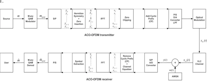
The block diagram of transmitter and receiver parts of ACO-OFDM shown in Figure 1.
Figure 4.1. ACO Block Diagram
In ACO-OFDM, only the odd subcarriers carry information bits while the even subcar-riers are ensuring that transmitted OFDM signal is strictly non-negative. Random generated source bits are transmitted in the blocks of duration of Tsym, modulated in M-QAM modulator and processed parallel in further blocks with blocks of duration Ts= Tsym/N . N is the total number of actively used subcarriers and for simplicity it has taken as equal to IFFT block size. The frequency domain modulated input signal of IFFT, X = [X0, X1, X2, ..., XN−1]T meets the Hermitian symmetry and comprises only odd subcarriers. The 0th (DC) and (N/2)nd subcarriers set to zero to avoid any complex term and satisfy Hermitian symmetry.
X[k] = ⎧ ⎨ ⎩ 0 , k is even XN−k∗ , k is odd (4.1)
where ∗ denotes the complex conjugation. Throughout this paper, lowercase letters will be used for time-domain signals and uppercase for discrete frequency-domain signals. The
resulting real, bipolar and anti-symmetric time-domain IFFT signal has the positive samples and N/2 delayed negatives of them x = [x0, x1, ....x2N−1]T is given by,
x[n] = 1 N
N%−1 k=0
X[k]ej2πkmN (4.2)
where N is the number of points in IFFT and Xm is the mth subcarrier of signal X. Due to Hermitian symmetry and zero insertion process unique data carried by subcarriers in ACO-OFDM is (N/4). A cyclic prefix (CP) is added to the discrete time output xCP
where G is the length of the cyclic prefix (CP) which Ncpequal to the maximum delay spread Ncp ≥ Lhin this paper.Negative part of the signal clipped to generate real and unipolar signal is given by,
⌊x[n]⌋c = ⎧ ⎨ ⎩ x[n] if x[n]≥ 0 0 if x[n] < 0 (4.3)
The clipping noise is generated after clipping will fall only on the even subcarriers and will not affect transmitted symbols carried by odd subcarriers which enables easy recovery of transmitted data and reducing complexity on the receiver circuitry as opposed to reduction of one fourth of the data rate. There is no need to add DC bias to the clipped signal in ideal systems so that, ACO-OFDM technique is more power efficient in terms of peak to average power ratio (PAPR) than DCO-OFDM. In this paper, it is assumed that D/A converter and op-tical modulator are ideal so that opop-tical-electrical conversion constant ζ and electrical-opop-tical conversion constant R is chosen as ζ = R = 1. At the receiver, ideal optical detector and A/D convertor detects and converts to optic-domain signals to electrical-domain. Received signal includes amplified/attenuated and interfered data symbols (ISI) as well as AWGN.
Received time-domain signal is of the form,
y(t) = x(t) ⋆ h(t) + w(t) (4.4)
where ⋆ denotes the linear convolution operation. h(t) = [h(0)h(1) . . . h(L − 1)]T is the L-path impulse response of the optical channel and w(t) is an AWGN that represents sum of the receiver thermal noise as well as shot noise which can be modeled as AWGN. Ambient noise radiation is modeled as DC and can be filtered out.It is important to notice that the AWGN being added in the electrical domain and overall noise power is denoted by σn.In this paper,ideal zero-forcing channel equalizer (ZF) is used at the receiver to mitigate effect of the channel.
hzf e(t) =FFT−1{1/Hch(f )} (4.5)
H is and Nx1 diagonal matrix whose diagonal elements are N point FFT. Cyclic prefix is removed and FFT of the signal has been taken. As a convention defined before FFT resulting frequency-domain signal is obtained as,
Y = [Y0, Y1, ..., Y2N]T (4.6)
M-QAM constellation symbols are extracted from the channel and noise corrupted signal and demapped to generate output bits ˆm.,
4.2.2. DCO-OFDM
A complete tranmitter and receiver of DCO-OFDM shown in Fig.2. The frequency-domain M-QAM complex data symbols are constrained to have Hermitian symmetry yielding
Figure 4.2. DCO Block Diagram
strictly non-negative symbols at the output of the IFFT. Hermitian symmetric signal. X0 = XN /2 = 0 are set to zero to make Hermitian symmetric.
Time-domain unipolar antisymmetric signal x obtained at the output of the IFFT. For large values of N(i.eN >= 64) the OFDM signal amplitude x could be approximated to zero mean and Gaussian random variable by using central limit theorem. In order to, avoid excessive DC bias, it is set to proportional with rms value of the signal.
BDC = k !
E{x2} (4.7)
where k is the clipping factor or proportionality constant and could easily be obtained after definition of the confidence interval of the Gaussian OFDM signal amplitudes. This is defined in the literature as 10log10(k2+ 1) dB bias .The DC bias added signal xDC(t);
Any remaining peaks after addition of DC bias BDC is clipped at zero to ensure non-negativity of the transmitted signal.Therefore,clipping noise results on the transmitted signal which is directly proportional to the clipping factor. Obtained real and unipolar signal is;
xDCO(t) = x(t) + BDC+ ncBDC (4.9)
where ncBDC is the clipping noise falls on the transmitted signal. The electrical signal modulates the intensity of the optical modulator. Therefore,OFDM signal amplitude propor-tional to the optical power. Because of that, OFDM signals have very high peak-to-average ratio and very high DC bias required to eliminate all negative peaks. The PDF of the xDCO(t) is a clipped Gaussian distribution is;
fxDCO(t)(v) = 1 √ 2πσD exp(−(v − BDC) 2 2σ2 D )u(v) (4.10) +Q(BDC σD )δ(t)
where u(v) is the unit step function and is δ(t) Direc delta function. Cyclic prefix(CP) is appended and converted to from parallel to serial (P/S). Signal passes through ideal D/A filter and optical modulator to make electrical-domain signal to optical-domain. Optical-domain signal directly passes from VLC model and exposed by AWGN in the electrical-domain. Ideal photodetector and A/D converter converts to signal to electrical domain back. Time domain signal y is input to the Fast Fourier Transform (FFT). Symbols extracted and M-QAM demodulation applied to resultant frequency-domain signal to obtain message signal back.
5. VLC SYSTEM DESING
5.1. Intensity Modulation/Direct Detection
Intensity modulation/direct detection (IM/DD) is fairly simple communication system where a LED is used for transmitter and a photodetector (such as photodiode or phototransis-tor) is used a receiver. Information is carried in the optical intensity of the light emitting diode, similar to amplitude modulation (analog) or amplitude shift keying (digital) systems. Opti-cals beams travels through the optical channel and effected by many noise sources (see noise sources section). These optical beams strike to the photodetector surface area and converted to electrical current by the photodetector. A transimpedance amplifier is used to convert generated current to a voltage. Finally received voltage is processed in receiver.
In traditional RF communications, signal is usually bipolar and complex. Bipolar sig-nals can have both positive and negative values. For VLC case, this situation is highly un-practical since intensity of an LED cannot be negative nor complex. Therefore, optical in-tensity signals must be both real and unipolar. Real and unipolar signals means that optical transmission signal is real and positive. This is the foremost constrain of a visible light com-munication system. This constrain also led to development of OFDM variants ACO-OFDM and DCO-OFDM.
5.2. Detection Noise and SNR 5.2.1. Noise Sources
An optical communication system can be effected by many noise sources. To obtain a fully fledged SNR definition, these sources should be investigated carefully. These are: photon fluctuation noise, dark current and excess noise and thermal noise. For fibre optic communication systems however, background radiation noise can be neglected since optic beams are isolated from background.
Photon Fluctuation Noise: Number of photons that are emitted from an optical source
per second fluctuates due to quantum nature of the device. This fluctuation is modelled as a noise. Photon fluctuation noise is mathematically defined as follows, where q is the elemen-tary electron charge, I is the current generated by photodetector and BW is the bandwidth of the photodetector device.
σpf2 = 2qIBW (5.1)
Dark Current and Excess Noise: It is the current that is generated when there is no optical
signal is received in photodetector. This sets the minimum current that can be detected. Its magnitude is determined by the photodetector area and material. It is very similar to photon fluctuation noise and can be modelled mathematically the same way
σ2dcex = 2qIBW (5.2)
Background Radiation: This environmental effect can be generated by ambient light or
sun. Mathematically,
Isky = S(λ)BW πω2/4
is the irradiance for the sky and,
Isun = A(λ)BW
is the irradiance of the sun where S(λ), A(λ) are the spectral radiance of the sky and the sun respectively, BW is the bandwidth of the photodetector, R is the photodetector responsivity and ω is the field of view of photodetector. Finally we have,
σbr2 = 2qIBW R(Isky+ Isun) (5.3)
elec-tronic device or material. Electrons’ free movements in the material induces a relatively small current. Mathematically modelled as following, where K is the Boltzmann’s constant, T is the temperature of the photodetector device, BW is the bandwidth of the photodetector device and Rloadis the impedance of the photodetector device.
σther2 = 4KT BW Rload (5.4) 5.2.2. SNR Definition SN Roptical = I2 p σ2 total = I 2 p σ2 pf + σdcex2 + σbr2 + σther2 (5.5)
Where Ipis the current generated by photodetector (when normalised resistance is used, this becomes the signal power), σ2
pf is the photon fluctuation noise power, σdcex2 is the dark current and excess noise power, σ2
bris the background radiation noise power, σther2 is the thermal noise power and σ2
dcex is the intensity noise power.
5.3. Simulation Results
In this section, computer simulation for the bit error rate (BER) performances of ACO-OFDM systems are investigated in the presence of realistic indoor optical channel models obtained by Zemax@ software,and compare with the AWGN channels with QPSK and 16 QAM signaling formats. 512 subcarriers were used in the simulations. For ACO-OFDM systems, the relationship between the optical power defined in 5.6 and the electrical power
is Popt,ACO=
!
Pelec,ACO/π. Normalizing the optical power we have [13],
Ebopt,ACO N0 = 1 π Ebelec,ACO N0 . (5.6)
ACO-OFDM as well as where an AWGN channel is employed. The four plots show the results for QPSK and 16-QAM constellations on the ACO-OFDM subchannels. The plots show the BER versus Eb,electrical/N0. From these plots it is observed the the performance results given in the literature for the BER versus Eb,electrical/N0. in the presence of only AWGN channels is far being realistic for the real optical communication channels. Consequently, it is utmost important and necessary to obtain and model realistic indoor optical channel models for efficient design of VLC systems in real applications. Similar results were obtained in Fig.5.2 for the the realistic channel configuration B except the BER curves are shifted according to the different properties of the configuration in terms of size the locations of transmitter and receiver and the materials use.
Configuration A 0 5 10 15 20 25 30 10 −4 10 −3 10 −2 10 −1 10 0 BER E b(elec) /N 0 (dB)
4 QAM AWGN 16 QAM AWGN 4 QAM Conf. A + AWGN 16 QAM Conf.A + AWGN
4 QAM Conf.A + AWGN 16 QAM Conf.A + AWGN
4 QAM AWGN 16 QAM AWGN
Configuration B 0 5 10 15 20 25 10 −4 10 −3 10 −2 10 −1 10 0 BER E b(elec) /N 0 (dB)
4 QAM AWGN 16 QAM AWGN 4 QAM Conf.B + AWGN 16 QAM Conf.B + AWGN
4 QAM AWGN 16 QAM AWGN 4 QAM Conf.B + AWGN 16 QAM Conf.B + AWGN
6. CONCLUSIONS and FUTURE RESEARCH
6.1. Conclusions
In this work, ACO-OFDM, a recently developed modulation scheme for IM/DD sys-tems is analyzed in the presence of realistic indoor optical channel models for two differ-ent channel configurations obtained by the Zemax@software. The BER performance of the ACO-OFDM system is investigated in the presence of the indoor optical channel impulse responses obtained for these two configurations as well as for different QAM constellations and compared with that of the AWGN channels. It was concluded that there are substantial performance differences between the cases where an indoor optical channel or an AWGN channel model is used. Consequently, we also concluded that it is not suitable to use the per-formance results of these types of systems solely based on the AWGN channel assumption for the ACO-OFDM scheme in designing such systems.
6.2. Future Research
Current LED technology is not intended for telecommunications applications rather just for illumination. Its electrical properties may not satisfy all the requirements for telecommu-nication applications. Thus, a new LED design should be beneficial for high performance visible light communication systems. Also better modeling of non-coherent LED character-istics in simulations will yield better results.
Full Name: Hüseyin Fuat Alsan
Birth Date & Place: 1988, İstanbul
Mobile Phone: 0536 825 29 11 Website: https://github.com/errmsg E-Mail: [email protected]
EDUCATION
Degree
Department
University
Year
B. Sc. Electronics Engineering Kadir Has University 2009 – 2013 (GPA:3.17/4.00)
M. Sc. (with Thesis) Electronics Engineering Kadir Has University 2013 – 2015 (expected) (GPA:3.43/4.00)
SUMMARY
I am an engineer who specialises in both hardware and software (a rare talent!). I can read and translate any document that is written in english.
-Nearly 10 years of UNIX-like experience (Ubuntu, Debian, Open SUSE, OS X) and BaSH scripting
-8 years of C/C++ experience (ANSI C, C++11 and C++14 included) (with OOP) -6 years of hardware and embedded design (PIC, Arduino, Raspberry Pi, Beaglebone) -5 years of MATLAB experience. I worked as a teaching assistant for MATLAB based telecommunication engineering classes. I though signal processing and telecommunication to undergraduate students. I also published several articles in IEEE.
-3 years of iOS (and some OS X) programming -2 years of FPGA experience (with verilog HDL) -1 year of Java SE programming with OOP
I am recently intrested in computational intelligence and their applications to various subjects (such as electrical engineering optimization problems). I also really enjoy developing apps for mobile platforms (mainly iOS)
SKILLS
• Computer Programming with C/C++, Java SE, MATLAB, Objective-C (iOS), Bash
scripting. FPGA programming with Verilog HDL and VHDL. • Experience in Linux, Linux CLI, Bash, Makefile, System Calls. • Telecommunication Simulations in MATLAB & Simulink.
• Microcontroller Programming with Assembly & C (PIC, Arduino).
• FPGA experience with Xilinx Spartan-3E and Altera DE2-115 education boards.
• Professional Proficiency English. • MS Office (World, Excel)
• LaTeX, BibTeX
EXPERIENCE
• Research Assistant (2013-2015) for TÜBİTAK Project Visible Light Communication with MIMO and OFDM
• Teaching Assistant (2013-2015) for courses EE-473 Digital Communication, EE-376 Communication Systems, CE-236 Electrical and Logic Circuits Lab.
• Internship at Bemka Emaye Bobin Teli ve Kablo Sanayi • Internship at Votel (Cwiz Communication Wizard) • Software Developer at Markakod interactive
PROJECTS
Markakod Interactive (June 2015 – September 2015)
I wrote an asynchronous socket class with Boost Asio library. Being asynchronous, this class could handle a lot TCP/UDP connections at the same time. I also wrote a class for interfacing with mongoDB. This class could take a JSON buffer from socket, parse it and carry the requested DB operation (which is embedded inside the JSON). such as insert, update, query and delete.
Graduate
1) Visible Light Communication with MIMO and OFDM (TÜBİTAK / Thesis Project) (Published Article)
2) Visible Light Communication with MIMO and OFDM (BAP Project) Hardware design of visible light communication with OOK modulation 3) MATLAB based Microwave simulator
GUI based simulator for various microwave engineering topics. Topics include: Transmission line parameters calculations, Smith chart calculations, RLC Matching networks, Stub matching, Amplifier design, Filter design.
Undergraduate
4) Signal Follower Robot (Graduation Project)
A small land robot which can track an ultrasonic signal source 5) Detection of Trojans in Integrated Circuits (Published Article)
A neural network is trained to discriminate Trojan signals from normal signals 6) MATLAB Simulation of Gaussian Pulse Shaping Detection in Wireless
Communications with Neural Networks (Wireless Communications Course Term Project)
A neural network is trained to decide if an incoming signal have been shaped by a Gaussian filter
7) MATLAB Simulation of Spectrum Sensing in Cognitive Radio with Neural Networks
(Wireless Communications Networks Course Term Project)
A neural network is trained to sense if AWGN channel is busy or free
Internship
8) Arduino based, network enabled energy monitoring system (Votel)
I used an Arduino UNO board with Ethernet shield to measure and log the energy usage of data centers. Cacti, SNMP and Xbee is used to implement the system. I coded the server with C in Ubuntu Linux.
PUBLICATIONS
A. Yeşilkaya, F. Miramirkhani, H. F. Alsan, E. Başer, E. Panayirci, M. Uysal, “Görünür Işık Kanallarının Modellenmesi ve Optik OFDM Sistemleri için Başarım Analizi”, Chamber of
Analysis of DCO-OFDM Systems In The Presence of Realistic Indoor Visible Light
Channels”, European Conference on Networks and Communications (EuCNC 2015) POS02: Poster Session 2, Paris, France, 22 June - 02 July 2015
A. Yeşilkaya, H. F. Alsan, F. Miramirkhani, E. Panayirci, H. Şenol, M. Uysal, "Görünür Işık Kanallarının Modellenmesi ve ACO-OFDM için Başarım Analizi", 23. Sinyal İşleme ve İletişim Uygulamaları Kurultayı (SİU), Malatya, May 2015
S. Baktır, A Ozmen, T. Gucluoglu, H. F. Alsan, M. C. Macit, "Detection of Trojans in Integrated Circuits", International Symposium on Innovations in Intelligent Systems and Applications (INISTA), Trabzon, July 2012
CERTIFICATES
Vodafone Red Academy “Data Everywhere!” Program Participation Certificate (2013)
RESEARCH INTRESTS
Telecommunications, Embedded System Design (Linux based), Microwave Engineering, Computational intelligence (neural networks mainly)
SOCIAL
Volunteer at IEEE WCNC’14 Istanbul
HOBBIES
• Electronic Music Instrument Design (Music Synthesizer & Theremin)
• Playing Keyboards in Bands
• Digital Music Synthesis & Production
OTHER
• Non-Smoker
• Class B Driving License • No Military Duty
Bibliography
1. Gfeller, F. R. and Bapst, U. H., ”Wireless In-House Data Communication via Diffuse Infrared Radiation,” Proc. IEEE, Vol. 67, No. 11, pp. 1474-1486, Nov. (1979).
2. Barry, J. R., [Wireless Infrared Communications], Kluwer Academic, (1994).
3. J. Amstrong, ”OFDM for Optical Communications”, J. Lightwave Tech., Vol. 27, No 3, pp 189-204, 2009.
4. S. D. Dissanayake, J. Amstrong, ”Comparison of ACO-OFDM, DCO-OFDM and ADO-OFDM in IM/DD Systems,” J. Lightwave Tech., Vol. 31, No 7, pp 1063-1072, 2013. 5. Sarbazi, E., Uysal, M., Abdallah, M. and Qaraqe, K., ”Ray Tracing Based Channel
Mod-eling for Visible Light Communications,” IEEE 22nd Signal Processing, Communication and Applications Conference (SIU), Trabzon, Turkey, April 2014.
6. Sarbazi, E. and Uysal, M., Abdallah, M. and Qaraqe, K., ”Indoor Channel Modeling and Characterization for Visible Light Communications, Invited Paper”, 16th International Conference on Transparent Optical Networks (ICTON), Graz, Austria, July 2014.
7. J. Armstrong, A. J. Lowery, ”Power efficient optical OFDM”, Electron. Lett., Vol. 42, No. 6, pp. 370-372, 2006.
8. Lee, K., Park, H. and Barry, J. R., ”Indoor Channel Characteristics for Visible Light Com-munications,” IEEE Commun. Lett., Vol. 15, No. 2, Feb (2011).
9. CREE LEDs, [Online]. Available at: http://www.cree.com.
10. Nguyen, H. Q. et al., ”A MATLAB-Based Simulation Program for Indoor Visible Light Communication System,” CSNDSP 2010, pp. 537-540, July (2010).
12. Kahn, J. M., Krause, W. J. and Carruthers, J. B., ”Experimental Characterization of Non-directed Indoor Infrared Channels,” IEEE Trans. Commun., Vol. 43, No. 234, pp. 1613-1623, Apr. (1995).
13. Chun, H., Chiang, C. and O’Brien, D., ”Visible Light Communication Using OLEDs: Illumination and Channel Modeling,” in Int. Workshop Opt. Wireless Commun., pp. 1-3, Oct. (2012).
14. J.M. Kahn and J. R. Barry, ”Wireless infrared communications,” Proc. IEEE, Volume. 85, No. 2, pp 265-298, 1997.
15. ”ASTER Spectral Library - Version 2.0,” [Online]. Available at: http://speclib.jpl.nasa.gov.
16. D. Tsonev, H. Haas, ”Avoiding spectral efficiency loss in unipolar OFDM for optical wireless communication”, IEEE Conf. Commun, Sydney, Australia, 2014.
17. W. H. Chen, C. H. Smith, S. C. Fralick, ”A fast computational algorithm for the discrete cosine transform,” IEEE Trans. Commun., Vol. 25, No 9., pp 1004-1009, 1977.
18. F. Miramirkhani, M. Uysal, ”Channel Modelling And Characterisation For Visible Light Communications,” IEEE Photonics Journal, Vol. 7, No. 6, December 2015
19. Z. Ghassemlooy, W. Popoola, S. Rajbhandari, ”Optical Wireless Communications Sys-tem and Channel Modeling with MATLAB,” CRC Press, 2013
![Figure 1.1. LOS Configurations [19]](https://thumb-eu.123doks.com/thumbv2/9libnet/4335740.71573/17.892.271.685.144.615/figure-los-configurations.webp)
![Figure 3.1. Spectral Power Distribution of Cree Xlamp® MC-E White LED [18]](https://thumb-eu.123doks.com/thumbv2/9libnet/4335740.71573/27.892.256.694.148.512/figure-spectral-power-distribution-cree-xlamp-white-led.webp)
![Figure 3.3. Empty room and reflections [18]](https://thumb-eu.123doks.com/thumbv2/9libnet/4335740.71573/28.892.267.697.163.539/figure-empty-room-and-reflections.webp)
![Figure 3.4. Empty room channel impulse response (reflections are ignored) [18] h(t) = N % i=1 P i δ(t − τ i ) (3.1)](https://thumb-eu.123doks.com/thumbv2/9libnet/4335740.71573/29.892.272.680.152.614/figure-room-channel-impulse-response-reflections-ignored-p.webp)
![Figure 3.5. Empty room channel impulse response (with first order reflections) [18]](https://thumb-eu.123doks.com/thumbv2/9libnet/4335740.71573/31.892.276.685.253.1024/figure-room-channel-impulse-response-order-reflections.webp)
![Figure 3.6. Comparison of channel impulse response for different order of reflections [18]](https://thumb-eu.123doks.com/thumbv2/9libnet/4335740.71573/32.892.183.791.394.900/figure-comparison-channel-impulse-response-different-order-reflections.webp)