El-Cezerî Fen ve Mühendislik Dergisi
Cilt: 7, No: 2, 2020 (536-542)
El-Cezerî Journal of Science and Engineering
Vol: 7, No: 2, 2020 (536-542) DOI :10.31202/ecjse.664132
ECJSE
How to cite this article
Yetgin A. G., Durmuş, B., “Analysis of the Effect of Rotor Slot Type on Torque Ripple in Induction Motors by Finite Element Method”, El-Cezerî Journal of Science and Engineering, 2020, 7(2); 536-542.
Bu makaleye atıf yapmak için
Yetgin A. G., Durmuş, B., “Asenkron Motorlarda Rotor Oluk Tipinin Moment Dalgalanması Üzerindeki Etkisinin Sonlu Elemanlar Yöntemi ile Analizi”,
El-Cezerî Fen ve Mühendislik Dergisi 2020, 7(2); 536-542.
Research Paper / Makale
Analysis of the Effect of Rotor Slot Type on Torque Ripple in Induction
Motors by Finite Element Method
Asım Gökhan YETGİNa,*, Burhanettin DURMUŞb
a
Electrical and Electronics Engineering Department, Burdur Mehmet Akif Ersoy University, Burdur, Turkey
bElectrical and Electronics Engineering Department, Kütahya Dumlupınar University, Kütahya, Turkey a[email protected]
Received/Geliş: 24.12.2019 Accepted/Kabul: 10.03.2020
Abstract: Induction motors are the most widely used motors in industry and home applications due to their
robust structure, cheapness, low maintenance and high efficiency. The torque-speed characteristic, which is one of the most critical parameters of induction motors, is highly influenced by rotor slot structures. Therefore, slot type and slot sizing should be performed properly to maximize motor performance during the design process of the induction motor. In the design stage of the induction motor, the choice of rotor slot structure, as well as other parameters are of great importance, while effects such as torque ripple, acoustic noise, and mechanical vibrations should be taken into consideration topics for motor designers. In this study, the effects of torque ripple in induction motors and the changes of torque ripple in different rotor slot structures are investigated. The analyses are performed using the Maxwell RMxprt program. Firstly, static motor models were created and analyzed in the RMxprt program. Afterward, 2-D models of the motors are created and analyzes are carried out to obtain torque ripple changes. 7 different slot geometries are used in the rotor slot structure. Rotor slot geometry with minimum torque ripple and the best performance criteria are determined from the motor models. A 90 kW, 3-phase, squirrel cage induction motor is used as the motor model. According to the obtained results, there was a 31.6% difference between the lowest and the highest torque ripple ratio.
Keywords: Induction motor, torque ripple, finite element method, rotor slot types.
Asenkron Motorlarda Rotor Oluk Tipinin Moment Dalgalanması
Üzerindeki Etkisinin Sonlu Elemanlar Yöntemi ile Analizi
Öz: Asenkron motorlar, sağlam yapıları, ucuz olmaları, az bakım gereksinimleri ve yüksek verimleri nedeniyle sanayi ve ev uygulamalarında en yaygın kullanılan motorlardır. Asenkron motorların en kritik parametrelerinden birisi olan moment hız karakteristiği rotor oluk yapılarına oldukça bağlıdır. Bu nedenle, asenkron motorunun tasarım sürecinde motor performansını en üst düzeye çıkarmak için oluk tipi ve oluk boyutlandırması düzgün şekilde gerçekleştirilmelidir. Asenkron motorun tasarım aşamasında, rotor oluk yapısının ve diğer parametrelerin seçimi büyük önem taşırken, moment dalgalanması, akustik gürültü ve mekanik titreşimler gibi etkiler büyük önem taşır ve motor tasarımcıları bu etkileri de dikkate almak zorundadır. Bu çalışmada, asenkron motorlarda moment dalgalanmasının etkileri ve farklı rotor oluk yapılarındaki moment dalgalanmasındaki değişiklikler araştırılmıştır. Analizler Maxwell RMxprt programı kullanılarak yapılmıştır. İlk olarak RMxprt programında statik motor modelleri oluşturulmuş ve analizler gerçekleştirilmiştir. Daha sonra motorların 2-D modelleri oluşturulmuş ve moment dalgalanmasındaki değişiklikleri elde etmek için analizler yapılmıştır. Rotor oluk yapısında 7 farklı oluk geometrisi kullanılmıştır. Minimum moment dalgalanmasına ve en iyi performans kriterlerine sahip rotor oluk geometrisi motor modelli belirlenmiştir. Motor modeli olarak 90 kW, 3 fazlı, sincap kafesli asenkron motor kullanılmıştır. Elde edilen sonuçlara göre, en düşük ve en yüksek moment dalgalanma oranı arasında %31,6’lık bir fark olduğu görülmüştür.
537
1. Introduction
The Induction Motor (IM) is widely used in industrial applications as a result of its robustness, low price, reliability and easy maintenance [1]. Besides, induction motors have been gaining increasing interest as a potential electrical machine type to compete with permanent magnet machines for traction applications that require variable speed and torque using power electronic converters. This is due to their rugged structure, technology maturity, and the elimination of expensive rare earth permanent magnets. Nevertheless, the parasitic effects such as torque ripple, acoustic noise, and mechanical vibrations remain challenging issues for machine designers. Analytical studies can provide physical insights to the problems, but cannot offer results as accurate as those o numerical calculations such as Finite Element Analysis (FEA) [2].
Torque ripple is caused by an interaction between the non-sinusoidal flux distribution from both stator and rotor currents and the Magnetomotive Force (MMF). The non-sinusoidal nature of the flux distribution can be attributed to two sources: the time harmonics produced by the inverter and the spatial harmonics from the machine design itself, due to the finite number of stator and rotor slots, discrete number of stator windings, and iron saturation effects [2]. Also, this component can be influenced by changes to the geometry of the machine design, the number of poles, the magnet angle, and the slot opening width are important parameters to have a look at [3].
Torque ripple have negative effects on induction motor performance and are as follows: Reduce the efficiency, increase the losses and reduce the life of the spare parts [1], it causes additional harmonic loss and it will try to induce speed ripple in a low inertia system [4], it causes acoustic noise and mechanical vibration [5], and it affects machine performance significantly in high precision position control applications [6].
Researchers have started to work on this subject in recent years in order to reduce the effect of torque ripple. Dip and friends’ paper implements a simple technique for the Direct Torque Control (DTC) of an induction motor which overcomes the trouble of high torque ripple afflicting the conventional DTC technique, this technique is quite simple and is appropriate for modern digital signal processors (DSPs) [7]. Ho-Hyun and his collogues’ paper aims to reliably evaluate the torque ripple of an optimal designed 3-phase induction motor using the measurement uncertainty theory [8]. In Te-Jen and friends’ article, model predictive torque control based on particle swarm optimization is proposed to modify the model predictive torque control in order to improve the control qualities, especially the steady-state torque ripples [9]. Koushik and et al.’s paper aims at further reduction in the pulsating torque by employing advanced bus-clamping switching sequences, which apply an active vector twice in a sub-cycle [10]. Ouahid and friends stated that torque ripple of induction motor can be significantly reduced by using Power Control Pulse Width Modulation (PCPWM) inverter [11]. Abdelli's paper describes a torque ripple reduction technique with constant switching frequency for direct torque control of an induction motor. Their method enables a minimum torque ripple control. They propose a control technique for induction motor in order to obtain a constant switching frequency and hence a torque ripple reduction [12]. In Kaboli and collogues’ paper, the effect of flux reference value on the torque ripple of a direct torque controlled induction motor is analyzed. The effect of flux value on torque ripple in a wide range of speed variations is investigated [13]. Ranjit and Inderderpreet present a Dynamic Fuzzy Logic based on Prediction Direct Torque Control (DFL PDTC) technique to reduce torque ripples within the squirrel cage induction motor. They stated that this DFL and PDTC combination reduces the high amount of torque ripple and improves the starting conditions in both low and high mechanical speeds of the motor [14].
When the studies in the literature are examined, it is seen that additional hardware and software tools such as power electronics, control algorithms, drive systems are used to reduce torque ripple.
538
In this study, to see the effect of torque ripple, induction motor models with different rotor slots have been created and rotor slot geometry with minimum torque ripple and best performance have been found. The objective of the paper is to determine which rotor slot type produces the least torque ripple ratio from motors with the same power, specification, and size.
2. Method and Motor Models
In motors with many design parameters such as induction motors, static and transient analyzes are difficult and time-consuming processes. Software such as the finite element method can easily perform both static and transient analyzes of the motor according to analytical methods. Besides, the accuracy of the obtained results is clearer. In this study, motor models were made in the Maxwell RMxprt program [15]. First, the geometric values of the motors, the materials, and the stator and rotor slot geometries were determined and static analyzes were performed. Then, transient analyzes were performed to obtain the change of torque ripple from motor models.
Nameplate values of 3-phase, squirrel cage induction motor used in the study are given in Table 1 [16].
Table 1. Induction motor nameplate values.
Parameters Value Power 90 kW Voltage 380 V Current 168 A Connection Star Frequency 50 Hz Power Factor 0.81 Rotor Speed 1463 rpm Nominal Torque 587 N.m
Number of Stator Slot 48 Number of Rotor Slot 38
In this study, 7 different geometries are used in rotor slots of induction motor. Rotor slot height and rotor slot mouth opening values were taken the same except slot 6 and slot 7.
539
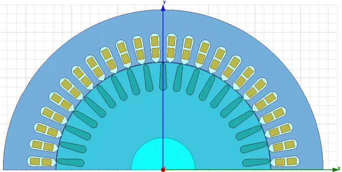
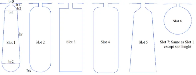
The differences in rotor slots are that the slot lower and upper width values and the end portions of the slots have a round or rectangular structure. Also, slot wedge height and width values are selected different values in order to avoid saturation between air-gap length and wedge. 2-D Maxwell image of the analyzed motor model (rotor slot geometry: Slot 1) is given in Figure 1. 7 different rotor slot geometries created for the analysis of torque ripple values are given in Figure 2. In motor models, dimensioning of stator frame and dimension values of stator slot geometry, winding structure, and core properties were taken the same. All parameters of the slot 7 except the slot height are the same as slot 1.
Figure 2. Rotor slot geometries used in modeling.
The values of the rotor slot parameters of the motor models are given in Table 2. Rotor slot height values are taken equally in other motor models except slot 6 and slot 7. Values are given in mm.
Table 2. Values of rotor slot parameters.
Parameters Symbol Slot 1 Slot 2 Slot 3 Slot 4 Slot 5 Slot 6 Slot 7
Slot Height hr 22.5 --- 33
Slot Mouth Opening br0 1.5
Slot Upper Width br1 5.5 8 8 8 6 14 5.5
Slot Lower Width br2 8 8 8 8 9 14 8
Slot Wedge Height h1 1 1.5 2 1.5 1.5 1.5 1
Slot Wedge Width h2 3 3 --- 2 2 --- 3
Radius Rs --- 4 0 2 0 --- ---
2.1. Torque ripple analysis
Torque ripple (Tmax - Tmin) value has been stated to increase the average torque value in some
studies in the literature [17]. At first glance, this may result in an increase in output power, but the values of the other motor parameters to be considered here. For this reason, taking a complete performance evaluation by taking into consideration the critical parameters such as losses and efficiency will be effective in achieving healthier results.
The ratio of torque ripple (% Tripple) in induction motors can be calculated using the formula given
in Eq. 1 [18]. In the equation, Tmax is the maximum torque value, Tmin is the minimum torque value,
Tavg is the average torque value.
% max min 2 ripple avg T T T T (1)
540
3. Analysis Results
The torque changes obtained for 7 different rotor slot geometries analyzed by the finite element method are given in Figure 3.
Figure 3. Torque changes for motor models.
When Figure 3 is examined, it is seen that each rotor slot geometry performs different torques and torque ripple ratio for 200 ms. It is seen that the minimum torque value is obtained from slot 6 with -823 N.m, and the highest torque value is obtained from slot 3 with 613 N.m.
The maximum, minimum, average torque values and the ratio of torque ripple obtained from each rotor slot geometry are given in Table 3.
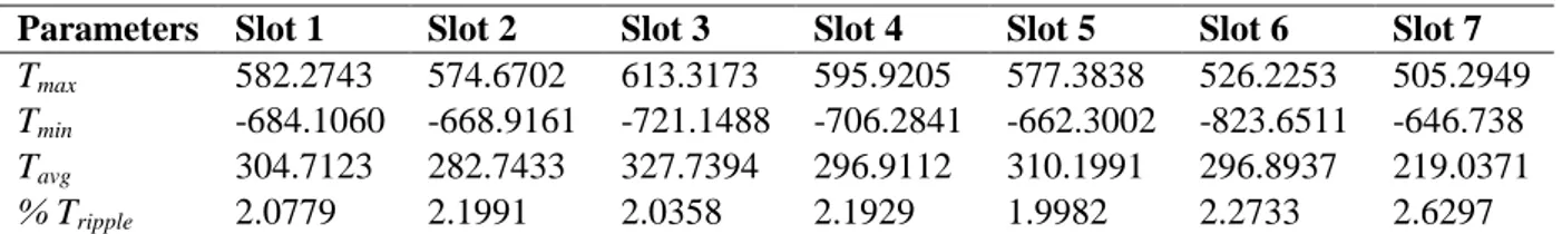
Table 3. Torques and torque ripple ratio values for 7 rotor slot geometries.
Parameters Slot 1 Slot 2 Slot 3 Slot 4 Slot 5 Slot 6 Slot 7
Tmax 582.2743 574.6702 613.3173 595.9205 577.3838 526.2253 505.2949
Tmin -684.1060 -668.9161 -721.1488 -706.2841 -662.3002 -823.6511 -646.738
Tavg 304.7123 282.7433 327.7394 296.9112 310.1991 296.8937 219.0371
% Tripple 2.0779 2.1991 2.0358 2.1929 1.9982 2.2733 2.6297
When Table 3 is examined, it is seen that torque ripple ratios obtained from motor models with equal rotor slot height values vary between 2% and 2.2%. It is observed that the small changes in
541
these ratios are caused by the lower and upper width values of the slots and the round or rectangular structure of the slots. The fact that the torque ripple ratios obtained from the motor models having the same slot height value is close to each other shows that the effect of other slot parameters is limited. It is seen that the torque ripple ratio increases if the slot geometry is a circle. This results in a reduction in the tooth width due to the slot geometry, which in turn causes the magnetic flux lines to oscillate in the air gap part without being able to fully migrate to the rotor.
It shows that the torque ripple ratio obtained from slot 7 increases rapidly with increasing slot height value. It is also seen that the minimum average torque value is obtained with 219 N.m of this slot type. Besides, although the maximum torque ripple ratio is obtained from slot 7, the torque oscillation value in this slot is the smallest with 1156 N.m.
As a result of static analysis, it was determined that the nominal torque values of the motor models have been changed ranged between 583 N.m and 588 N.m. It is concluded that the slot type to be selected for this motor model is the slot 5 type which gives the minimum torque ripple ratio.
4. Conclusions
In this study, the torque ripple ratios of the motor were determined by using the finite element method for 7 different slot geometries. According to the obtained results, it was concluded that the upper and lower width values of the slot did not make an effective difference in the torque ripple ratio. It was seen that the torque ripple ratio increased and the average torque value decreased with increasing slot height value. Considering that there is a ratio of 31.6% between the lowest and highest torque ripple ratio, it is seen that the slot height is the critical parameter for the torque ripple ratio. The effect of such a ratio on the vibration and noise of the motor will be more clearly recognized. It was also found that the maximum torque ripple ratio does not mean that it would have the largest torque oscillation.
In the future studies, different rotor slot geometries can be analyzed by optimizing the slot height value.
References
[1]. Settar, S. K.; Ahmed, N. A.; Hatem, F. F.; Mohd, R. B. D., Three Phase Induction Motor Torque Ripple Minimization based on A Novel Nonlinear Dynamic Inverse Controller, The National Conference for Postgraduate Research, January 2016, Universiti Malaysia Pahang, pp. 321-329.
[2]. Yingjie, L.; Silong, L.; Bulent, S., Analysis of Pulsating Torque in Squirrel Cage Induction Machines by Investigating Stator Slot and Rotor Bar Dimensions for Traction Applications, IEEE Energy Conversion Congress and Exposition, 15-19 September 2013, Denver, CO, USA, pp. 246-253.
[3]. https://www.emetor.com/glossary/torque-ripple/ [available]: 15.09.2019.
[4]. Hayder, S. H.; Hanan, M. D.; Alwash, J. H., Torque Ripple Reduction based Direct Torque Control for Induction Motor Drive, Int. J. Eng. Res. Technol., 2014, 3(12): 1024-1032.
[5]. Alexander, P.; Ing Habil, A. M., Reduction of Torque Ripple in Induction Motors by using A Modulated Rotor, GMM-Fachbericht 89: Innovative Klein-und Mikroantriebstechnik, 27–28 September 2017, Saarbrücken, pp. 57-62.
[6]. Siavash, S.; Leila, P., Improved Technique for Minimizing Torque Pulsation in Halbach Array Permanent Magnet Machines, COMPEL: Int. J. Comput. Math. Electr. Electron. Eng., 2012, 31(6): 1590-1602.
542
[7]. Dip, V. T.; Parminder, S.; Amandeep, K., A Novel Procedure for Torque Ripple Minimization of an Induction Motor, Int. J. Eng. Innovative Technol., 2017, 7(4): 26-33.
[8]. Ho-Hyun, L.; Kyung-Il, W.; Han-Seok, P.; Dae-Kyong, K., Evaluation of Torque Ripple of an Optimal Designed 3-Phase Induction Motor using Uncertainty, Universal J. Electr. Electron. Eng., 2019, 6(3A): 68-73.
[9]. Te-Jen, S.; Tung-Yeh, T.; Shih-Ming, W.; Tsung-Ying, L.; Hong-Quan, V., Torque Ripple Reduction of Induction Motor based on A Hybrid Method of Model Predictive Torque Control and Particle Swarm Optimization, Adv. Mech. Eng., 2016, 8(10): 01–13.
[10]. Kaushik, B.; Prasad, J. S. S.; Narayanan, G., Reduction of Torque Ripple in Induction Motor Drives using an Advanced Hybrid PWM Technique, IEEE Trans. Ind. Electron., 2010, 57(6): 2085-2091.
[11]. Ouahid, B.; Mohamed, S. B.; Abederrezzek, C., Minimizing Torque-Ripple in Inverter-Fed Induction Motor using Harmonic Elimination PWM Technique, Induction Motors - Modelling and Control, IntechOpen, 2012, pp. 01-23.
[12]. Abdelli, R.; Rekioua, D.; Rekioua, T., Performances Improvements and Torque Ripple Minimization for VSI Fed Induction Machine with Direct Control Torque, ISA Trans., 2011, 50: 213-219.
[13]. Kaboli, S.H.; Zolghadri, M. R.; Haghbin, S.; Eskandari, P., Investigation on the Flux-based Torque-Ripple Behavior in DTC based Induction Motor Drives, Iran. J. Sci. Technol. Trans. A., 2008, 32(A1): 07-16.
[14]. Ranjit, K. B.; Inderderpreet, K., Torque Ripple Reduction of Induction Motor using Dynamic Fuzzy Prediction Direct Torque Control, ISA Trans., 2019.
[15]. Ansys Maxwell 2D Field Simulator User’s Guide, Motors-Three Phase Induction Machine, 2019.
[16]. Lazaridis, T., General Design Data of A Three Phase Induction Machine 90 kW–Squirrel Cage Rotor, Technical Report, 2016, pp. 01-15.
[17]. Raul, R., Torque Ripple, Vibrations, and Acoustic Noise in Switched Reluctance Motors, Hait J. Sci. Eng. B., 2005, 2(5-6): 776-786.
[18]. Mostafa, J. K.; Babak, G., Modification in Geometric Structure of Double-Sided Axial Flux Switched Reluctance Motor for Mitigating Torque Ripple, Can. J. Electr. Comput. Eng., 2015, 38(4): 318-322.