phys. stat. sol. (b) 244, No. 4, 1188 – 1191 (2007) / DOI 10.1002/pssb.200674504
© 2007 WILEY-VCH Verlag GmbH & Co. KGaA, Weinheim
Planar bilayer metamaterial with left-handed transmission
and negative refraction at microwave frequencies
Atilla Özgür Çakmak*, 1, 2, Kaan Guven1, 3, and Ekmel Özbay1, 2, 3 1 Nanotechnology Research Center, Bilkent University, 06800 Ankara, Turkey
2 Department of Electrical and Electronics Engineering, Bilkent University, 06800 Ankara, Turkey 3 Department of Physics, Bilkent University, 06800 Ankara, Turkey
Received 19 September 2006, revised 25 November 2006, accepted 6 December 2006 Published online 22 March 2007
PACS 41.20.Jb, 42.70.– a, 78.20.Ci, 81.05.Zx
A planar composite metamaterial consisting of bilayers of metal cutwire pairs and long wire pairs which are separated by a thin dielectric layer is designed and fabricated for microwave frequencies. The simu-lated and experimentally measured transmission spectra of the metamaterial and its individual compo-nents (cutwire-only and wire-only) indicates that the metamaterial exhibits a transmission band within the common stop bands of its components, and thus acts as a medium with negative index of refraction. The existence of n < 0 is further supported by a refraction experiment.
© 2007 WILEY-VCH Verlag GmbH & Co. KGaA, Weinheim
1 Introduction
Metamaterials are artificial structures with tailored electromagnetic response to the incident electromag-netic excitation at the desired frequency band. The unusual property of the metamaterials is that they can behave like a medium with negative effective index of refraction, neff < 0 [1 – 3]. Decades ago, it was
predicted that such a medium would exhibit completely novel electromagnetic phenomena [4], yet no naturally occurring material had been known to exist to support the theories experimentally.
The first composite metamaterial (CMM) design consists of stacked dielectric layers on which planar metal wires and metal split ring resonator (SRR) arrays have been printed periodically [1]. The combined electric responses of the SRR and wire elements provide an effective plasmon cutoff frequency, ωp, be-low which the permittivity, ε(ω), becomes negative. When the magnetic field component of the incident electromagnetic wave is normal to the SRR plane, the inductance of the rings and the capacitance at the gaps generate a resonance at a particular frequency, ωm. For frequencies ωm< ω, the effective permeabil-ity, µ(ω) becomes negative. Hence, the CMM may act as a medium with ε(ω) < 0, µ(ω) < 0, for ωm < ω < ωp. These materials are also called left-handed materials due to the axes formed by the
electromagnetic field vectors. A one dimensional metamaterial can be constructed by stacking SRR and wire layers alternatingly. There are numerous studies which employ different SRR/wire patterns for metamaterials. Most of these designs adhere to the aforementioned SRR topology. In this case, the elec-tromagnetic wave vector is required to be in the plane of metamaterial layers and significant number of layers should be stacked to provide sufficient thickness for the incident field. This requirement turned out to be a major drawback for the fabrication of the CMMs at infrared and optical frequencies [5 – 8]. Recently, a different topology for obtaining magnetic resonance is proposed and demonstrated [9]. The SRR is replaced by metal cutwire strips separated by a dielectric layer, like a parallel plate capacitor
phys. stat. sol. (b) 244, No. 4 (2007) 1189
www.pss-b.com © 2007 WILEY-VCH Verlag GmbH & Co. KGaA, Weinheim
Original Paper
(see Fig. 1). The magnetic field parallel to the plane of metal strips can induce a resonance which leads to µ(ω) < 0. This allows the electromagnetic field to propagate normal to the CMM plane, as opposed to the parallel propagation of the former SRR/wire topology. As a consequence of this idea, a number of new metamaterial studies have been reported [10 – 12].
In this paper, we employed this new topology to design, and fabricate a CMM for microwave frequen-cies. We measured the transmission spectra of the CMM and its cutwire and wire components separately, and demonstrated that the CMM exhibits a transmission band in the common stop bands of the cutwire-only and wire-cutwire-only structures. A negative refraction experiment is performed which independently provides support for the existence of negative index of refraction of the CMM within the left-handed transmission band that is already obtained from the transmission spectrum. The paper is organized as follows: The CMM design and fabrication details are given in the next section. Third section describes the transmission and negative refraction experiments.
2 Planar bilayer metamaterial design and fabrication
The bilayer is fabricated from dielectric layers (thickness d = 0.4 mm, dielectric constant εr = 4.2) with a
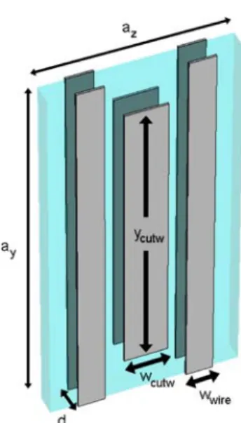
metal coating (thickness t = 30 µm) on both sides. Figure 1 shows the schematic view of the CMM unit cell. d is the thickness of the dielectric spacer between the pair elements. The cutwire dimensions are wcutw = 0.8 mm, ycutw = 5.5 mm, and the wire dimensions are wwire = 0.5 mm, ywire = 7.0 mm. The unit cell
has dimensions ax = 2.0 mm, ay = 7.0 mm, az = 3.5 mm. ax is the stacking periodicity in the propagation
direction. With these parameters, the simulated cutwire structure exhibits a magnetic resonance around, fm ≈ 14 GHz. The wire units are designed with a high cut-off frequency in order to ensure the ε < 0 within
the µ < 0 stop band of cutwires. The wires are present on either side of the bilayer for symmetry.
3 Transmission
measurements
The transmission spectra of the CMM, cutwire-only and wire-only structures were measured in free space, by a HP8510C Network Analyzer and a set of antennas. We employ a similar analysis conducted for SRR/wire type CMM in order to identify the left-handed transmission band [13]. Figure 2(a) and (b) summarize the measurement and simulation results, respectively. The ωp of the wire-only structure is very high, thus satisfying ε(ω) < 0 within the indicated stop band that spans the measured frequency range. The cutwire only structure exhibits a clear resonance gap around 14.25 GHz. In order to particu-larly identify this phenomenon, we used a complementary structure in which the cutwire pairs are elec-
Fig. 1 (online colour at: www.pss-b.com) Schematic view of the bilayer metamaterial. The cutwires and wires are located on both sides of a thin dielec-tric layer, d. The unit cell contains one paired cutwire and two paired long wire elements. The geometrical parameters and periodicity of the structure are given in the text. The electromagnetic wave propagates in the x direction with the electric field in the y direction and the magnetic field in the z direction. The bilayers are stacked in the x direction with periodicity ax.
1190 A. Özgür Çakmak et al.: Planar bilayer metamaterial with left-handed transmission
© 2007 WILEY-VCH Verlag GmbH & Co. KGaA, Weinheim www.pss-b.com
Fig. 2 (online colour at: www.pss-b.com) (a) Measured and (b) simulated transmission spectra of the CMM and its individual components. The left-handed transmission peak of the CMM around 14.25 GHz appears in the magnetic resonance gap of the cutwires. The transmission band extending from 15.5 to 17 GHz is right handed. Note that the electrically shorted cutwire pairs does not exhibit the magnetic resonance gap, which leads to the absence of the left-handed peak for the shorted CMM.
trically shorted through the dielectric layer. Shorting the cutwire pairs removes the capacitive coupling of the cutwire pair, and therefore demolishes the resonance. Thus, the gap is guaranteed to be due to the magnetic resonance.
The CMM exhibits two distinct peaks. The transmission peak between 14.0 – 14.5 GHz coincides with the magnetic resonance of the cutwires. The shorted CMM which incorporates the shorted cutwire pairs does not show this peak. The transmission band between 15.5 – 16.5 GHz is right handed, since it is common to both CMM and the shorted CMM. We note that the cutwires couple to the electric field as well, which has a dominating effect on the overall electric response of the CMM. Indeed, if the ε(ω) < 0 behaviour of the CMM were due to the wires only, the aforementioned right-handed peak should not be present.
The simulations are performed by commercial software (CST Microwave Studio®). In the simulations, the structure is assumed to extend infinitely along the lateral directions. We anticipate that the finite size
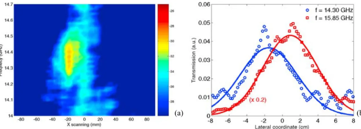
Fig. 3 (online colour at: www.pss-b.com) (a) Frequency vs. lateral spatial distribution of the transmitted signal at the CMM surface for 10° incidence. Warm color indicates higher transmission. (b) Lateral power profiles taken at f = 14.30 GHz and f = 15.85 GHz from the left-handed and right-handed bands, respectively. The f = 15.85 GHz profile is scaled to fit. The incident signal (not shown) is centred at the origin.
(a) (b)
phys. stat. sol. (b) 244, No. 4 (2007) 1191
www.pss-b.com © 2007 WILEY-VCH Verlag GmbH & Co. KGaA, Weinheim
Original Paper
of the fabricated structures in the y direction may have an effect on the electric response of the CMM. Nevertheless, all the essential features of the experimentally observed spectra were obtained by simula-tions, with a good agreement in their respective spectral position.
4 Negative refraction measurements
In order to confirm that the CMM acts as a medium with neff < 0, we performed a negative refraction
experiment using a bulk CMM structure consisting of 4 layers. The electromagnetic signal is incident at 100 to the center of the CMM surface from the left side of the origin. The transmitted signal is scanned laterally along the exit surface of the CMM. Figure 3(a) shows the lateral and frequency distribution of the transmitted signal with color coded transmission level. Evidently, the beam transmitted within the left-handed band appears on the left side of the origin, indicating that the beam refracted negatively upon entering the CMM. The lateral power profile taken at f = 14.3 GHz (within the left handed band) con-firms the negative lateral shift of the beam. Figure 3(b) shows the lateral power profiles taken at f = 14.3 GHz (within the left-handed band) and at f = 15.85 GHz (within the right-handed band). Evi-dently, the lateral shift of the profiles agrees with the anticipated sign of the neff for each transmission
band.
5 Conclusion
In this work, we designed and fabricated a composite metamaterial for normal-to-plane propagation at microwave frequencies. The transmission properties of the CMM and its components are measured and simulated. The paired cutwire units are demonstrated to exhibit a magnetic resonance. A distinct left-handed transmission band is observed for the CMM. The existence of a negative effective index of re-fraction for this band is confirmed by a rere-fraction experiment. This type of metamaterial is very suitable for scaling to higher frequencies, due to the extremely compact design and easily adjustable thickness. This CMM topology may become feasible for integration in various microwave applications.
Acknowledgements This work is supported by the European Union under the projects EU-DALHM, EU-NOE-METAMORPHOSE, EU-NOE-PHOREMOST, and TUBITAK under projects No. 104E090, 105E066, 105A005. One of the authors (Ekmel Ozbay) also acknowledges partial support form the Turkish Academy of Sciences.
References
[1] D. R. Smith, W. J. Padilla, D. C. Vier, S. C. Nemat-Nasser, and S. Schultz, Phys. Rev. Lett. 84, 4184 (2000). [2] R. A. Shelby, D. R. Smith, S. C. Nemat-Nasser, and S. Schultz, Appl. Phys. Lett. 78, 489 (2001).
[3] R. A. Shelby, D. R. Smith, and S. Schultz, Science 292, 77 (2001). [4] V. G. Veselago, Sov. Phys. Usp. 10, 504 (1968).
[5] T. J. Yen, W. J. Padilla, N. Fang, D. C. Vier, D. R. Smith, J. B. Pendry, D. N. Basov, and X. Zhang, Science 303, 1494 (2004).
[6] S. Linden, C. Enkrich, M. Wegener, J. Zhou, T. Koschny, and C. M. Soukoulis, Science 306, 1351 (2004). [7] C. Enkrich, M. Wegener, S. Linden, L. Zschiedrich, F. Schmidt, J. F. Zhou, T. Koschny, and C. M. Soukoulis,
Phys. Rev. Lett. 95, 203901 (2005).
[8] H. O. Moser, B. D. F. Casse, O. Wilhelmi, and B. T. Saw, Phys. Rev. Lett. 94, 063901 (2005).
[9] V. M. Shalaev, W. Cai, U. K. Chettiar, Hsiao-Kuan Yuan, A. K. Sarychev, V. P. Drachev, and A. V. Kildishev, Opt. Lett. 30, 3356 (2005).
[10] G. Dolling, C. Enkrich, M. Wegener, J. F. Zhou, C. M. Soukoulis, and S. Linden, Opt. Lett. 30, 3198 (2005). [11] J. Zhou, L. Zhang, G. Tuttle, T. Koschny, and C. M. Soukoulis, Phys. Rev. B 73, 041101 (2006).
[12] S. Zhang, W. Fan, N. C. Panoiu, K. J. Malloy, R. M. Osgood, and S. R. J. Brueck, Phys. Rev. Lett. 95, 137404 (2005).