November 15, 2004 / Vol. 29, No. 22 / OPTICS LETTERS 2623
Experimental observation of true left-handed transmission
peaks in metamaterials
Koray Aydin and Kaan Guven
Department of Physics, Bilkent University, Bilkent 06800, Ankara, Turkey
Maria Kafesaki
Research Center of Crete and University of Crete, Heraklion, Crete, Greece
Lei Zhang and Costas M. Soukoulis
Ames Laboratory, U.S. Department of Energy, and Department of Physics and Astronomy, Iowa State University, Ames, Iowa 50011
Ekmel Ozbay
Nanotechnology Research Center and Department of Physics, Bilkent University, Bilkent 06800, Ankara, Turkey
Received June 29, 2004
We report true left-handed (LH) behavior in a composite metamaterial consisting of a periodically arranged split ring resonator (SRR) and wire structures. We demonstrate the magnetic resonance of the SRR structure by comparing the transmission spectra of SRRs with those of closed SRRs. We have confirmed experimentally that the effective plasma frequency of the LH material composed of SRRs and wires is lower than the plasma frequency of the wires. A well-defined LH transmission band with a peak value of 21.2 dB 共20.3 dB兾cm兲 was obtained. The experimental results agree extremely well with the theoretical calculations. © 2004 Optical Society of America
OCIS codes: 120.7000, 260.2110.
In 1968, Veselago predicted that a medium with negative permittivity e and negative permeability m will exhibit unusual physical properties such as negative refraction, reversal of Doppler shift, and
backward ˇCerenkov radiation.1
In such a medium the electric, magnetic, and wave vector components form a left-handed coordinate system; hence the name left-handed material is used for description. Recently this idea was experimentally investigated by construction of a composite metamaterial (CMM)
consisting of two components that have e共v兲 , 0 and
m共v兲 , 0 simultaneously over a certain frequency
range.2,3
Whereas a medium with e , 0 can easily be achieved, e.g., by periodically arranged metallic wires,4
obtaining m共v兲 , 0 was a challenge because
of the lack of a magnetic charge. Pendry et al. suggested that a periodic array of metallic split ring
resonator (SRR) structures exhibits m共v兲 , 0 close to
magnetic resonance frequency vp.5 Various studies
that employed different structure designs extended this investigation.2,3,6 – 8 Negative refraction of elec-tromagnetic waves at the interface of CMMs was also observed,9 – 11
which supports the existence of a left-handed material.
The existence of passbands for CMM within the re-spective stop bands of SRR-only and wire-only media is intuitively considered evidence of left-handed
behav-ior. In this Letter, by measuring vpfor the CMM and
for wire-only structures, we demonstrate experimen-tally that the dielectric response of the CMM differs substantially from that of the wire-only medium. It is evident that a shift in plasma frequency renders the
aforementioned intuitive approach inapplicable. This is a new attribute that was not recognized in previous research. Based on this observation, we present a new CMM structure that exhibits true left-handed behav-ior and has a transmission band with a peak value at
21.2 dB. To our knowledge, this is the highest
trans-mission value reported for a left-handed material. In general, a SRR structure exhibits both magnetic resonance5induced by the splits at the rings and elec-tric resonance12
induced by the dipolelike charge distri-bution along the incident electric field. A bandgap in the transmission spectrum of a periodic SRR medium may be due to negative e or negative m or solely to the periodicity. The ambiguity can be lifted by use of a structure in which the splits in the ring resonators are closed. This will destroy the magnetic resonance but maintain the electric resonance. A frequency gap that is present in the transmission spectrum of the SRR medium but not in that of the closed split ring reso-nator (CSRR) medium will then correspond to m , 0.
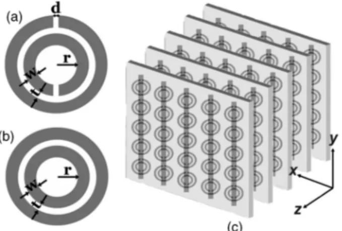
The SRR [Fig. 1(a)] and CSRR [Fig. 1(b)] units are fabricated on a FR4 circuit board with a deposited cop-per layer of 30-mm thickness.6
The geometric
param-eters of the SRR are d苷 t 苷 0.2 mm, w 苷 0.9 mm, and
r苷 1.6 mm, as shown in Fig. 1(a). The circuit board
has a 1.6-mm thickness and dielectric constant e苷 4.4.
SRR units are arranged periodically, with 5, 15, and 18 unit cells in the x, y, and z directions, respectively. The dimensions of a unit cell containing a single SRR
are ax苷 ay 苷 8.8 mm and az 苷 6.5 mm.
Transmis-sion measurements are performed in free space, where, unlike in a waveguide measurement, no restriction on
2624 OPTICS LETTERS / Vol. 29, No. 22 / November 15, 2004
Fig. 1. Schematics of (a) a single SRR, (b) a CSRR, (c) a periodic CMM composed of SRRs on one side and wires on the other side of a dielectric board.
the size of the structures is imposed. The experimen-tal measurement setup consists of a HP 8510C network analyzer and a set of microwave horn antennas for
dif-ferent parts of the frequency spectrum. The incident
field propagates along the x direction, with E and H along the y and z directions, respectively.
Figure 2 shows the measured transmission spectra of periodic SRRs and CSRRs from 3 to 14 GHz. The first bandgap (3.55 –4.05 GHz) of the SRR medium is not present in the CSRR medium, indicating that m , 0. The second bandgap (8.1 – 11.9 GHz) is present for both the SRR medium and the CSRR medium. This measurement clearly shows that the stop bands of a SRR medium cannot be automatically assumed to be negative-m behavior. Some of the observed gaps could also originate from the electrical response of the SRRs or from Bragg gaps that are due to periodicity.
Another point to be discussed is the electric response
of the CMM. Previously reported transmission
re-sults did not emphasize the contribution of the electric
response of SRRs to that of wire structures. However,
it was recently found12
that the SRRs, in addition to
their resonant magnetic response at vm, exhibit a
resonant response at a higher frequency vo that has
an electric character. This behavior is similar to that of a periodic cut-wire medium that exhibits a stop band with a well-defined lower edge that is due to
the discontinuous wire geometry.8 As a result, the
SRRs contribute to the effective permittivity of the CMM, causing a downward shift in the plasma
fre-quency determined solely from wire structures.12
To demonstrate this effect we used a CMM consisting of periodic alternating layers of CSRRs and wires. The thickness, length, and width of the wires were 30 mm, 13.5 cm, and 0.9 mm, respectively. Figure 3 displays the measured transmission spectra of wire-only media and CMMs consisting of CSRR and wire layers. The
vpof the wire-only structure near 8 GHz is reduced to
5.3 GHz within the closed CMM structure. As shown
in Fig. 3, vp of the CMM is lower than that of the
wire-only medium alone. It is crucial to determine whether the shift in plasma cutoff frequency covers the magnetic resonance gap, which would render the CMM a right-handed medium.
We have designed the present SRRs such that the first bandgap of a SRR structure at 3.55 – 4.05 GHz is not obscured by this shift. The CMM structure is
made from Nx 苷 5, Ny 苷 15, and Nz 苷 24 unit cells.
Each unit cell has a single SRR and a copper wire that comprises stacked SRR and wire layers [Fig. 1(c)], with
lattice spacings ax苷 ay 苷 8.8 mm and az 苷 6.5 mm.
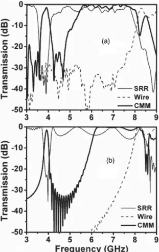
The transmission spectra for SRR only, wire only, and CMM periodic structures are displayed in Fig. 4(a). The simulation results [Fig. 4(b)] agree well with the experimental data.
The CMM structure permits propagation of electro-magnetic waves at 3.6–4.1 GHz, where both e and m are negative. The CMM passband exactly coincides
with the stop band of the SRR. The transmission
peak at 3.9 GHz is 21.2 dB, which is a signif icantly high value for a material made from metals. Simi-larly, the simulations predict a transmission peak at 3.92 GHz of 21.5 dB. We stress that a similar transmission band is not present for a CMM composed of CSRRs and wires (Fig. 3). The electric response contribution of SRRs is also evident here: If vpof the
wire-only structure [dashed curve in Fig. 4(a)] were used to identify the e , 0 regime for the CMM, the transmission from 5.3 to 8 GHz would have occurred in a regime with e , 0 and m . 0, which is not possible.
Fig. 2. Measured transmission spectra of a periodic SRR medium and a periodic CSRR medium from 3 to 14 GHz.
Fig. 3. Measured transmission spectra of wires and closed CMMs (CCMMs) achieved by periodic arrangement of CSRRs and wires.
November 15, 2004 / Vol. 29, No. 22 / OPTICS LETTERS 2625
Fig. 4. Transmission spectra of SRRs, wires, and open CMMs: (a) experiment and (b) simulation.
However, as Fig. 3 suggests, the e . 0 regime of the combined electric response of SRRs and wires starts at 5.3 GHz.
In conclusion, we have successfully demonstrated true left-handed behavior in free space with a high transmission peak. The left-handed transmission band exactly coincides with the region where both dielectric permittivity and magnetic permeability take negative values. By closing the splits of the SRRs, we experimentally verif ied the magnetic resonance of
the SRR structures. Using this procedure, one can
successfully identify the regions of negative perme-ability and negative permittivity of SRR structures.
We also conf irmed experimentally that vp of the
CMM composed of SRRs and wires is lower than wires-only plasma frequency vp, as is essential for the
design of CMM structures and the interpretation of transmission spectra. Finally, our detailed numerical calculations agree quantitatively with the experimen-tal results.
We thank T. Koschny and E. N. Economou for useful discussions. This work was supported by EU– DALHM, by Defense Advanced Research Projects
Agency contract MDA 972-01-2-0016, and by
EU–METAMORPHOSE. The Ames Laboratory is
operated for the U.S. Department of Energy by Iowa State University under contract W-7405-Eng-82. E. Ozbay acknowledges partial support from the Turkish Academy of Sciences. K. Aydin’s e-mail address is [email protected].
References
1. V. G. Veselago, Sov. Phys. Usp. 10, 504 (1968). 2. D. R. Smith, W. J. Padilla, D. C. Vier, S. C.
Ne-mat-Nasser, and S. Schultz, Phys. Rev. Lett. 84, 4184 (2000).
3. R. A. Shelby, D. R. Smith, S. C. Nemat-Nasser, and S. Schultz, Appl. Phys. Lett. 78, 480 (2001).
4. J. B. Pendry, A. J. Holden, D. J. Robbins, and W. J. Stewart, J. Phys. Condens. Matter 10, 4785 (1998). 5. J. B. Pendry, A. J. Holden, D. J. Robbins, and W. J.
Stewart, IEEE Trans. Microwave Theory Tech. 47, 2075 (1999).
6. M. Bayindir, K. Aydin, P. Markos, C. M. Soukoulis, and E. Ozbay, Appl. Phys. Lett. 81, 120 (2002).
7. K. Li, S. J. McLean, R. B. Greegor, C. G. Parazzoli, and M. H. Tanielian, Appl. Phys. Lett. 82, 2535 (2003). 8. E. Ozbay, K. Aydin, E. Cubukcu, and M. Bayindir,
IEEE Trans. Antennas Propag. 51, 2592 (2003). 9. R. A. Shelby, D. R. Smith, and S. Schultz, Science 292,
77 (2001).
10. C. G. Parazzoli, R. B. Greegor, K. Li, B. E. Koltenbah, and M. Tanielian, Phys. Rev. Lett. 90, 107401 (2003). 11. A. A. Houck, J. B. Brock, and I. L. Chuang, Phys. Rev.
Lett. 90, 137401 (2003).
12. T. Koschny, M. Kafesaki, E. N. Economou, and C. M. Soukoulis, Phys. Rev. Lett. 93, 107402 (2004).